Mar 9, 2009 at 10:04 PM
High beams issue!
1995 TOYOTA CAMRY
Advertisement
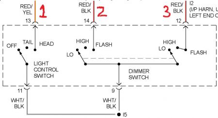
I've got that wiring diagram and even tho it says red/black , There is no red/black wire in the wiring harness going up to the switch on the steering column. The #14 pin in the connecter(where the 2 bundles of wires come together on the steering column)is a red/white wire .

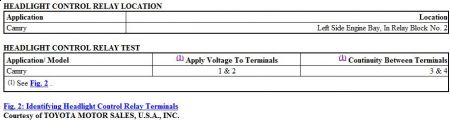
check the voltage of the wire .. then jumper it to the #4 on the relay ..then does the switch work correctly ??

Mar 9, 2009 at 10:11 PM
Advertisement
I believe that wire has 12 volts but I can't check til tomorrow.I blew a fuse and don't have a replacement. I go in the morning and get one and then I'll don the check. Talk to you tomorrow.
Mar 9, 2009 at 10:21 PM
Hey Mike
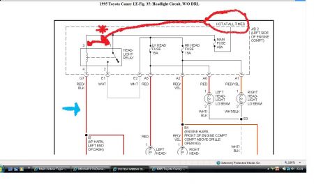
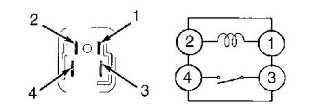
You now have a HOT going to #1 and #3 @ relay because you jumped them ...(see red arrows on diagram) so the fault you now have MUST be on the wire from #4 going (see blue arrow on diagram) to #'s 13 and 14 on the switch or the switch itself is still faulty !!! If you ground out #4 on the relay to the chassis your lights will work all the time ?? they won't be switched !!! you have a permanent live and a permanent ground to the relay !!! let me know

Mar 9, 2009 at 10:41 PM
The lights come on when I hooked up #4 to ground with #1&3 connected. When I was checking my pins on the old switch I found the 3rd one over from the end ( I believe it's #12 wire) of the connecter burned as if it had been shorted. So I went out to the car and disconnected the new switch and there was also a burned area on the opposing pin in the connecter going out to the relay box. The color of the wire is red/black. It doesn't appear to have hurt the wire except the plastic around the pin was melted. I never noticed it when I installed the new switch. This may have been the original problem as to why the hi beams weren't working properly. Now I have to decide on a plan to fix the problem. Question- when the HL relay is engaged shouldn't all 4 legs have 12volts on them?
Mar 10, 2009 at 9:54 AM
He Mike ... good morning
I'm getting a little confused now (ha) .. you stated 3/4 post's back that there was NO red/black wire going to the switch ? you are now saying you have a burn't red/black wire/pin on switch ?? am I correct in saying we NOW have 12 volts to #1 and #3 and you have a burn't plastic surround on the red/black wire/pin on the SWITCH pin #12 is for ground from HL switch high/flash to pass direct to HL bulbs and could well be the problem !!
When you grounded #4 relay pin direct to chassis .. the switch did not work but the lights came on ... am I correct ??
Also #4 should never be HOT (12 volts) it is the ground from the switch it energizes the relay
#1 = HOT all times (12 volts)
#3 = HOT all times (12 volts)
#4 = 0 volts @ all time's
#2 = 0 volts with light's switched OFF @ switch
#2 = HOT when relay is energized (12 volts) when light are SWITCHED ON at switch
The HOT from #3 and the GROUND from #4 energize the relay when the light switch grounds out #4 sending the power to #2 on the relay
The #12 on the switch GROUNDS the HIGH/FLASH TO PASS bulbs .. hope this helps and iv'e not confused you .. as I said I'm getting a little confused and have to keep going back over the prior post's ..(ha ha) .. let me know

Mar 10, 2009 at 10:40 AM
To ground, YES. Terminal 4 may not be a full 12 volts, but you should have + voltage at all 4 terminals.
Mar 10, 2009 at 10:41 AM
ooppsss .. sorry James is quite correct you will get some voltage showing on #4 ... I think I need to go back to bed ...LOL ..

Mar 10, 2009 at 10:53 AM
That's OK Dave I know how easy it is to make a slip and man I appreciate all your input. They say communication or the lack there of causes most of the problems we have and sometimes I'm not the best at it. I didn't realize that there would be 2 different color wires at the connecter and so I was looking at the wires on the switch side of the connecter which is red/yellow but on the relay side of the connecter it's red/black. I'm sorry for the confusion.
Mar 10, 2009 at 3:21 PM
I don't normally drive this car my grandaughter does and I was talking to her this morning and she told me they drove the car with the headlights on all the time and when they shut the key off the lights went off , and each time they started the car the lights would automatically come on. So I did some checks using the ign. switch. With the ign.on and HLswitch off I got 12 volts on all the legs except #2. With the ign.on and the HL switch on I got12 volts on #1, 0 volts on #2, and 8 volts on #3&4.I don't know if that means anything or not.
Mar 10, 2009 at 3:39 PM
Hey Mike.
No problem ... so how are we doing on the repair ?? have we gotten any further ??

Mar 10, 2009 at 4:17 PM
I'm kinda at a standstill right now. I'm wondering if two wires could be shorted together somewhere between the connecter on the steering column and th JBox. I just can't understand, when the ignition is on and the HL switch is on,why does #3&4 leg show 8 volts. That's the reason the relay isn't kicking in.
Mar 10, 2009 at 5:32 PM
Sorry I didn't see your last post before this one .. for some reason I wasn't notified you had replied ?
OK lets try this !! jumper JUST #13 on the switch to #3 on the relay .. this will take out of the equation the itergration relay ???????????
Wait a minute ... did you say you had a YELLOW/RED wire coming from #12 and #13 coming off the switch ?? let me know

Mar 10, 2009 at 6:05 PM
I can't believe I didn't check this sooner .... your vehicle IS fitted with DRL (daytime running light's) ??? the LO headlight's are supposed to be on constantly ???
Mar 10, 2009 at 6:29 PM
Dave: The #12 wire on the switch side of the connecter is red/yellow. #13 wire on the switch side of the connecter is red. The #14 wire on the switch side of the connecter is red/white. As far as having DRL, I don't think this car has them because we've always been able to turn the lights off when the car is running. Also from looking at my Haynes manual it indicates that only the canadian models had the DRL"s. Did you want me to jump #3 to#13?
Mar 10, 2009 at 8:17 PM
Well, we're going to have to back up here a few yards, and punt. Dave and I had a little chat off line and he informed me that we probably were looking at the wrong diagram for your system. I believe he is correct. Of the diagrams I sent you, do the wire colors on the W/DRL diagram match the colors on your system? Please advise.
Mar 10, 2009 at 9:00 PM
James: From what I can see the colors don't match up with the DRL schematic and like I said in a previous comment DRL's stay on all the time and mine didn't.
Mar 10, 2009 at 9:39 PM
Hey Mike. good morning
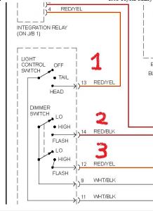
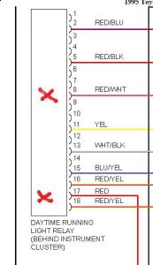
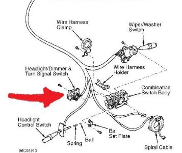
OK heres the deal mike, I had a chat with James and we discussed your problem and we looked back over the post's .. and we also re-checked both wiring diagrams, I have even looked the wiring diagram's for the years below 93/94 and above 96/97 and they are all identical ... there are no RED or RED/WHITE wires .. unless you are actually working on the DRL MODULE (see diagrams)and NOT the H/L SWITCH ... Also the DRL module sends the GROUND through a Dimmer Relay ...this would explain the voltage drop you are getting ... Could you possibly supply us with a photo of the switch and connector you keep mentioning .. I do not understand what connector you are talking about ? the #13 wire (red/yellow)should go from switch to intergration relay then change to a red/black wire from relay to relay ..the #14 (red/black) should go directly to #4 on HL relay there should be no connector in between ? let me know your thought's ??
without DRL

Mar 11, 2009 at 6:50 AM
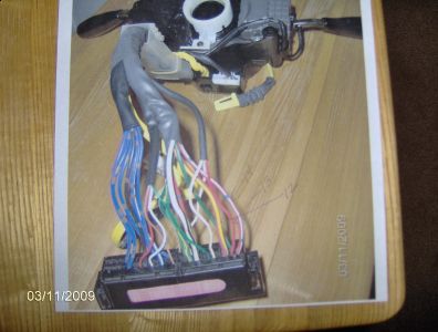
This is a picture of the switch and connecter I marked #'s 12,13,&14.the red/white is the 1st wire#14, the red wire is the 2nd, #13, the 3rd from the right Red/yellow is #12. There are eleven wires in the HL bundle.
Mar 11, 2009 at 7:59 AM
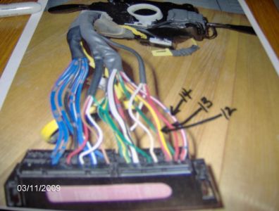
Maybe this might be a little clearer.
Mar 11, 2009 at 8:19 AM
Hey mike.
I'm not showing a connector on my wiring diagram as you know ... so heres what i need to know !!
on your photo you have a blu/white wire marked as #14 what color wire goes to this on the other part of the connector also the same for the other 2 .. what color goes tor the red #13 and what color goes to the yellow # 12 .. what are the color of the wires coming from the car to this connector ?? I also need you to locate the actual H/L switch connector past this junction block up on the arm and tell me how many wires you have going to just this switch !! remove the big grey plug on the arm and see if the connectors are numbered ...let me know
Mar 11, 2009 at 9:26 AM
The wire #14 is red/white there are little blue dots on the wire so that's why it may seem blue. the other side of the connecter is red/black. The #13 red wire has a red/yellow on the other side of the connecter.the #12 red/yellow wire has a red/black on the other side of the connecter. When you say switch up on the arm, are you refering to the actual combination switch under the steering wheel? If so then the on/off switch has 3 wires a red and 2 whites, the wires on the dimmer part of the switch are red/white,red/yellow,black/white,blue/red. I didn't see any #'s on the wires. I hope I understood you right. If not let me know.
Mar 11, 2009 at 1:01 PM
Hey Mike.
Sorry not replied sooner .. work/family commitments !! .. well I have looked at the pictures and your last post .. and I have to say i'm even more confused ..LOL .. none of the wires we have on our diagrams are matching up with your wires ... are you sure this is a 1995 toyota camry .. LOL .. could you supply the VIN # of the vehicle while I have a think about where to go/do next and study the post's again !!!
Thanks

Mar 11, 2009 at 8:48 PM
I need to know how many and what colors the wires are here !!

Mar 11, 2009 at 9:35 PM
the wires are red/yellow , red/white , black/white , blue/red ,and then there are 3 green wires for the turn signals ( 2 green/white & 1 green/black) Vin# 4t1sk12c3su496838 the title says 95 camry
Mar 11, 2009 at 9:54 PM
OK it is a 95 2.2L LE camry from kentucky ? Well even though the wiring colors are different we have to go with NO DRL as there are only 4 wires coming from the switch !! the black/white is ground to chassis .. the red/yellow must be to the intergration relay and onto (black/red wire ?) the H/L relay #4 pin the other 2 wires red/white and blue red we do not really need to worry about as they seem to be working correctly but i'm guessing the blue/red is to the #4 relay pin also and the red/white is the ground from dimmer to H/L high beam bulbs ?? does this sound about right to you ? let me know ..
ALSO do you still have a jumper wire on #1 and #3 on the relay but all other wires are as should be no jumpers anywhere else ?? everything is back in place correctly ??
let me know

Mar 11, 2009 at 10:33 PM
Everything sounds OK except I don't know about the blue/red wire as to whether it goes to the #4 pole or not. I took the jumper off 1&3. Here's something else I learned a little while ago. My grandaughter told me she always left the light switch on and the lights would automatically come on when she started the car and then when she stopped the car and opened the door and got out the lights would shut off.
Mar 11, 2009 at 10:45 PM
I know we are going over old ground .. but could you check voltage @ #1 and #3 now (no jumper) then put the relay back in .. and test light switches all positions ...
If you have no voltage @ #3 jumper it again so we definately have 12 volts @ #1 and #3 then test the lights again ...
If the lights are not working correctly !! put a jumper wire form the RED/YELLOW wire connector PIN on the SWITCH ITSELF .. NOT the multi connector .. then try the lights again ... let me know ... I realise it is getting late so let me know if you are going to do this in the morning ??

Mar 11, 2009 at 10:58 PM
That's a good idea .I'll do what you ask 1st thing in the morning. goodnight
Mar 11, 2009 at 11:03 PM
Dave and I conversed on this earlier and I think what he meant was::: 3rd paragraph.
If the lights are not working correctly !! put a jumper wire from the RED/YELLOW wire connector PIN on the SWITCH ITSELF..NOT the multi connector--- (connect the other end of this wire to terminal "4" on the HL relay)---.. then try the lights again...let me know ETC.
If the lights are not working correctly !! put a jumper wire from the RED/YELLOW wire connector PIN on the SWITCH ITSELF..NOT the multi connector--- (connect the other end of this wire to terminal "4" on the HL relay)---.. then try the lights again...let me know ETC.
Mar 12, 2009 at 12:27 AM
Hi James: I thought maybe you had given up on me. I have a question before I connect the red/yellow up to #4 pole. With #3 pole jumped to #1 then #4 shows 12 volts so if I connect #4 to the red/yellow, wouldn't it be like shorting it to ground? Also James what do you think about the lights coming on and off automatically with the car being started. Do you think there might be another relay in the circuit that makes this happen?
Mar 12, 2009 at 8:30 AM
Good morning Mike.
With #1 and #3 not jumped what voltage do you get @ each ..and #4 ??
when jumped there should be NO voltage @ #4 untill the H/L switch is turned on

Mar 12, 2009 at 8:42 AM
as for the light coming on and off !! I think it is due to a bad connection ... remember #1 and #3 are hot all times .. not just @ key on .. with the light switch in the ON position all the time and #3 and #1 HOT all the time the lights would be on constantly even with ignition OFF because it is still making the circuit ... there would have to be a timer relay somewhere on the system for the light to time out after exiting the vehicle !!

Mar 12, 2009 at 8:53 AM
With switch off#3 not jumped I get 0 volts on all poles except #1 has 12 volts. With switch on #3 not jumped I get 12 volts on #1 0 volts on #2 and 8 volts on #'s 3 and 4. When #3 is jumped I get 12 volts at each pole except #2 with the switch off. When I turn the switch on with #3 jumped it's about the same except #4 dropped to 10 volts.
Mar 12, 2009 at 9:13 AM
Dave I just noticed something on your relay sketch .I've been numbering them different than you. Your #1 is my #4 , #2 is my #3 , #3 is my #2 , #4 is my #1. I don't know how this happened.
Mar 12, 2009 at 9:32 AM
I am not understanding this mike .. test 1 & 2 below are the same test with different result's ?? Also your how are the lights working with your last test ??
(1)With#3 not jumped I get 0 volts on all poles except #1 has 12 volts.
(2)With #3 not jumped I get 12 volts on #1 0 volts on #2 and 8 volts on #'s 3 and 4.
(3)When #3 is jumped I get 12 volts at each pole except #2 with the switch off.
(4)When I turn the switch on with #3 jumped it's about the same except #4 dropped to 10 volts.
Mar 12, 2009 at 9:38 AM
I don't think I explained it correctly about the lights. What I was asking was , when the H/light switch was on and you started the car then the lights wouild come on automatically and then when you turned the car off and opened the door the lights would turn off automatically.
Mar 12, 2009 at 9:40 AM
I modified my previous message showing when the switch was on & off.
Mar 12, 2009 at 9:48 AM
I got no lights with any test.
Mar 12, 2009 at 9:51 AM
OK can we do the test'e again using my relay terminals LOL .. and see what we get .. remove the jumper and lets start from the begining .. check the voltages (no jumper) on each terminal with lights off and lights on .. let me know ...
If you leave the light switch in the ON position .. theoretically the light's would be ON all the time ..because #1 and #3 are HOT all times and #4 from switch grounds it out ..and the swith would be in the ground postion with light's switched on .. no matter if the key is ON or OFF .. why they would go out when you open the door I have no clue about unless there is a timer relay which our diagrams are not showing ???

Mar 12, 2009 at 9:55 AM