Mar 12, 2009 at 10:05 AM
High beams issue!
1995 TOYOTA CAMRY
Advertisement
Dave: I know where I got my numbers for the relay. I got them from the Mitchill schematic that James sent me at the beginning of our discussions. Are you saying the schematic is wrong?

I am using Mitchell the same as James ..so we are both giving you the same diagrams !!
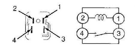
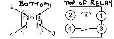
These are the correct terminal number's ... is this what your relay looks like ?? the diagram is not an exact replica of the fusebox or how it is sat .. this could be causing the confusion !!.. on the wiring diagram the relay may be turned around and plugged in a different way ?? Use this diagram to check your PIN voltages please ?

Mar 12, 2009 at 10:19 AM
Advertisement
Jumped #1&3 with H/L switch off #1 is 12 volts , #2 is 12 volts , #3 is 12 volts ,#4 is 0 volts . Jumped #1&3 with H/L switch on #1 is 12 volts , #2 is 10 volts , #3 is 12 volts , #4 is 0 volts. Not jumped H/L switch off #'s 1,2,3, are 12 volts , #4 is 0 volts . Not jumped H/L switch on #'s 1&2 are 8 volts , #3 is 12 volts , #4 is 0 volts.
Mar 12, 2009 at 10:42 AM
OK and do the light's work in any ... especially the last test ??
Jumped #1&3 with H/L switch off #1 is 12 volts , #2 is 12 volts , #3 is 12 volts ,#4 is 0 volts .
Jumped #1&3 with H/L switch on #1 is 12 volts , #2 is 10 volts , #3 is 12 volts , #4 is 0 volts.
Not jumped H/L switch off #'s 1,2,3, are 12 volts , #4 is 0 volts .
Not jumped H/L switch on #'s 1&2 are 8 volts , #3 is 12 volts , #4 is 0 volts.

Mar 12, 2009 at 10:53 AM
no
Mar 12, 2009 at 11:09 AM
OK ground out #4 to chassis or a good ground point !..does anything work now, the light's should come on .. but with no switch control ??

Mar 12, 2009 at 11:21 AM
nothing , no lights , with switch off and on
Mar 12, 2009 at 11:40 AM
I've got to go out for awile I'll check back later this afternoon.
Mar 12, 2009 at 12:03 PM
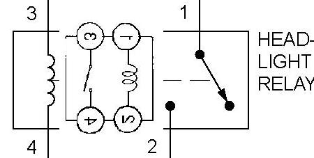
You are saying "Not jumped H/L switch off #'s 1,2,3, are 12 volts , #4 is 0 volts" ... we should not have voltage @ #2 with switch off .. unless our diagram of the relay is also wrong like the wiring diagram ?
This is what we should have (not jumped) switch off
#1 12 volts
#2 0 volts
#3 12 volts
#4 0 volts
not jumpered switch on (if it is working)
#1 12 volts
#2 12 volts
#3 12 volts
#4 slight voltage increase
How are we getting power @ #2 with the switch off ??
OK jumper #3 to #2 with the light's switched ON
Take out the relay and check what voltage we have coming from battery to J/B .. 2 of the pins should have 12 volts and 2 should have 0 volts with relay removed !!
Also try jumpering #3 to #2 with the light's switched ON the light should work but not be able to be switched off !!
let me know

Mar 12, 2009 at 12:10 PM
Dave: could you have James give me a call. He asked for and I sent him my ph. # it's 361 578 6705. thanks
Mar 12, 2009 at 3:34 PM
Sure .. I don't know if he is actually online in the forum at the moment as he has not answered a message I sent him earlier .. but i will forward your request to him .. no problem !!

Mar 12, 2009 at 3:50 PM
Dave: I'm still wondering if I'm understanding correctly the picture you sent of the relay posted thur. mar 12 2009 at 7:19 a.m. Am I looking at the bottom of the relay on the left view or am I looking down on the J/B socket? If I were to put that left view on top of the relay on the wiring diagram you sent on monday mar. 9 at 6:45 a.m. how would it fit?
Mar 13, 2009 at 8:26 AM
Hey Mike.
I think James had family commitments yesterday, so let's try this .. the diagrams are showing the relay terminals but I want you to use the corresponding terminals on the JUNCTION BOX for the test's OK.
First check the R/H and L/H headlight fuse's and bulbs to make sure we have not blown them !
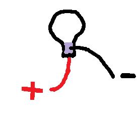
Do you have a test light ? if not, can you make one like this .. get a bulb from the car(flasher bulb) connect (solder)a red wire to the bottom pin of the bulb and (solder)a black wire to the metal surround at the bottom of the glass .. like this

Mar 13, 2009 at 8:45 AM
In answer to your question to James !!
Mar 13, 2009 at 9:12 AM
Dave :I know your gonna think I'm a real dummy but help me understand please. Can you transpose the top view of the relay on the right to the relay on the wiring diagram dated mon. Mar. 9 at 6:45 a.m. this would help me considerably. When I get that I think I can perform the tests better. Thanks Mike
Mar 13, 2009 at 9:26 AM
I can see where your confusion is coming from ??
Mar 13, 2009 at 11:21 AM
There aren't any #'s on my relay and there are 2 large and 2 smaller legs and they are also offset just like your picture. So which #'s are we gonna use?
Mar 13, 2009 at 12:13 PM
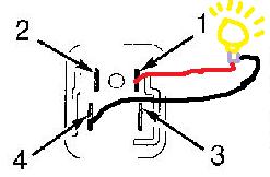
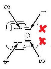
OK we should have 2 hot's @ all time, one large terminal and one small !! using the test light I asked you to make ... put the black wire to battery or chassis ground point .. use the red wire to probe which 2 are HOT with the relay removed from the vehicle ... we should get one of the smaller terminals hot making the other smaller terminal #2 and we should get one of the large terminals hot making the other large terminal #4 do you agree !! even if we are not correct we can figure out which is #2 and #4 by putting in the relay after we know for sure which are the hot @ all times... remember remove the relay and test on the cars J/B, find me the 2 hots please mike and we will take it from there, once you have located 2 hots we will use the diagram on the last post marked with the 2 red crosses as both our references for terminal numbers OK .. sound good !!
Let me know

Mar 13, 2009 at 12:32 PM
I have a small hot and a large hot. #'s 1 and 3.
Mar 13, 2009 at 1:08 PM
OK ...leave the relay out... using the test bulb ... put red wire to # 1 small terminal female connector on J/B .... and put test bulb black wire to the large female connector #4 on J/B ... turn onthe H/L switch ...this should light up the bulb .. if it does turn off the H/L switch ... the bulb should be out with H/L switch OFF
If you then swap RED test bulb wire to large female connector # 3 on J/B ...and leave the black test bulb wire to #4 female connector on J/B ... you should get the same result's ... test bulb on with H/L switch ON and test bulb OFF with H/L switch OFF ...
let me know

Mar 13, 2009 at 1:28 PM
The 1st test the bulb lit up but the H/L switch had no effect on it. The 2nd test the bulb did not lite up and was not affected by the switch
Mar 13, 2009 at 1:48 PM
OK try the same test's but instead of the black test bulb wire going to #4 put it to #2 ... let me know

Mar 13, 2009 at 1:57 PM
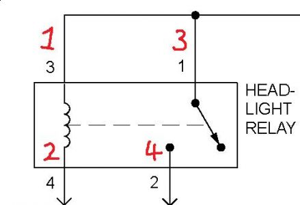
Dave: On the wiring diagram how about lets change #1 to #3 and #2 to #4. Is that ok with you?
Mar 13, 2009 at 2:26 PM
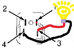
I do not understand why !! but yes !! do you mean like this ... we are going to use this diagram as a reference point for both of us ???
Mar 13, 2009 at 2:39 PM
Dave: You never said but are you allowed to call on the phone? If so and you want to call that would be ok with me. I might save some time.To answer your last post YES that's what i've been wanting.thanks
Mar 13, 2009 at 2:49 PM
I can call you later .. just not at the moment .. can we carry on with these test's this way for now !! ..
So we are upto... black test bulb wire in new #4 and red test bulb wire to new # 3 first and then new # 1 next .. and testing if the H/L switch works with these test's .... also did you check the H/L bulbs and fuse's ??
Let me know

Mar 13, 2009 at 2:59 PM
#1 to #4 light on switch has no affect #3 to #4 light on and again switch has no effect
Mar 13, 2009 at 3:08 PM
OK now put the RED test bulb wire in new #2 terminal ... and put the relay back in (so we have the red test bulb wire and the relay in new #2 terminal) and put the black test bulb wire to the battery or chassis ground and test the switch now .. the difference here is ... if the fuse's and H/L bulbs are good (not blown) then our test bulb should come on with H/L switch and the cars H/L should also come on !!
Did you check the fuse's and H/L bulbs ?
let me know

Mar 13, 2009 at 4:17 PM
put red in #2 and installed relay, no light with H/L switch on or off. Fuses and H/L lamps are OK.
Mar 13, 2009 at 4:47 PM
Dave: I can take my finger and close the points on the relay #'s 3&4 and the H/L come on and work fine. The problem I have is I can't figure out how to energize the relay so the coil works and pulls the points together.
Mar 13, 2009 at 4:54 PM
mmmmmmmmmmm
OK take relay ...out wire #1 and #3 terminal's on RELAY direct to battery HOT ... Red wire from test bulb to relay new #2 terminal ....and black wire from test bulb to CHASSIS ground ... then wire # 4 RELAY terminal direct to BATTERY ground !! the test bulb should now light up ... then if that works ... wire the new #4 terminal direct to RED/YELLOW terminal on H/L switch and see if the H/L switch light's up the test bulb ON and OFF ??
Let me know

Mar 13, 2009 at 5:14 PM
Dave: I got the H/L's to work with the switch. Here's what I did-- with the relay installed , I wired #1 & #3 together so both were hot , then I took #2 wire and jumpered it into one of the white wires coming out of the H/L switch. When I did this the H/L's worked perfect and functioned in Hi , Lo , and flash. But I don't know what to do to make it permanant and I don't know where the malfunction is in the circuit.
Mar 13, 2009 at 7:21 PM
hey hey Mike !!
Well done ... but my questions are this .. there was no white wire on the H/L switch .. there was a white and black .. which is the switch to ground .. why did you have to jumper #1 and #3 they both were HOT last time you posted ..??
Anyway no matter .. if you did use the white/black at the H/L switch and jumped it to #2 then you grounded terminal #2 so the break is between the switch and the relay ground ..?? terminal #2 is the old terminal # 4 which we stated all along was the ground !!
Is the switch working correctly now in all positions and lights going off when switch turned OFF ..
let me know

Mar 13, 2009 at 7:38 PM
Hey Mike.
I need to know the voltage of the "white" wire you have jumpered to .. when the switch is in the ON position and the OFF position also when in HIGH position .. so we can figure out how to make it permanent !!
Let me know

Mar 13, 2009 at 8:09 PM
I'll get that info to you 1st thing in the morning.
Mar 13, 2009 at 9:01 PM
Hey Mike..
OK speak tommorrow good night !

Mar 13, 2009 at 9:05 PM
Dave: On page 7 of the posts dated wed. Mar. 11 10:01 A.M. I mentioned there were 3 wires coming from the H/L on off switch , a red and 2 whites , also 7 other wires coming from the dimmer switch and turn signals , it's one of these white only wires coming from the on off switch that I am jumpered to. Now the reason I have to jump 1 & 3 together is because when the relay is out 1 & 3 show 12 volts each but when I put the relay in 3 continues to show 12 volts but #1 only shows 8 volts ( why , I don't know ). Now as to the voltage of the white wire that I'm jumping to , With the relay out H/L switch on I get 0 volts. With relay out H/L switch off I get 8 volts. With relay in H/L switch on I get 0 volts , With relay in H/L switch off I get 12 volts ( I think the reason for the increase in voltage is due to my jumping 1 & 3 ). Now as to the switch working when it's jumped , the answer is yes , it works in all positions. Now where do we go from here?
Mar 14, 2009 at 8:27 AM
Good Morning Mike.
OK .... I'm still not getting these white wires .. I have been through all my wiring diagrams that relate to the H/L switch and the flashers and other systems going up to the multifunction switch ...I cannot find any refernce to "white" wires ... but the diagrams seem to be wrong somewhere ? ..
OK humour me here ...the jumper the from #4 take off the white wire and put to the RED/YELLOW wire on the SWITCH itself and let me know what happens ..does the switch work ? leave your other #1 and #3 jumper in place ??
Dave H
Mar 14, 2009 at 9:20 AM
I don't have a jumper on #4 , I have it on #2 . I took the jumper off #2 and put it on red/black nothing happened but when I put it on red/yellow , it worked perfect.
Mar 14, 2009 at 9:47 AM
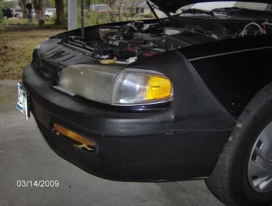
Dave reread my previous post. Something I just noticed is that my front parking lights aren't working when the lights are on or off.This is the light next to the headlight.I wonder if that could be tied into my problem.
Mar 14, 2009 at 10:03 AM