Troubleshoot wiring harness 68236867AD repair?

2015 CHRYSLER TOWN AND COUNTRY
195,000 MILES • 3.6L • 6 CYL • 2WD • AUTOMATIC
Avatar
TIMOTHY HUFF
  • MEMBER
  • 36 POSTS
Vehicle tries to start, barely. Engine turns over catches a little bit then just turns over and over. Current 7 codes from my Inova 5610:
P1628 sensor reference voltage 2 erratic.
P0600 serial communication link.
P0340 camshaft position sensor circuit bank 1 sensor 1
P0335 crankshaft position sensor circuit
P0345 camshaft position sensor circuit bank 2 sensor 1
P0365 camshaft position sensor circuit bank 1 sensor 2
P0390 camshaft position sensor circuit bank 2 sensor 2

I'm trying to verify the condition of wiring harness #68236867AD Specifically the camshaft and crankshaft position circuits. I am hoping you can provide wiring diagrams connector diagrams pinouts and possible voltage and resistance at those connectors. I am an electrician and I know how to use a tester. I also know how to fix wires. I would gladly work with you completely on this repair seeing as information has been hard to find. I'm usually very good with Google.
Jan 20, 2024 at 1:13 PM
Advertisement
Avatar
TIMOTHY HUFF
  • MEMBER
  • 36 POSTS
I'm looking for a way to do a simple continuity test. I will unplug the PCM connector, I will unplug the camshaft position sensor, and if I know the pin numbers on both connectors, I can check its continuity. I could also check to see if that wire has continuity to ground. Or continuity to each other of the wires at the camshaft position sensor.
Jan 20, 2024 at 1:59 PM
Avatar
CARADIODOC
  • CERTIFIED EXPERT
  • 34,306 POSTS
Sorry to take so long. The only diagrams I have access to are rather miserable compared to Chrysler's diagrams. It takes a long time to format them for uploading. These seven are for Powertrain Management. The last four are for your connectors. If you give me some time, I can do the same thing for the fault code diagnostic steps.
Jan 20, 2024 at 5:55 PM
Advertisement
Avatar
STEVE W.
  • CERTIFIED EXPERT
  • 15,113 POSTS
With all of those codes I don't think you need to do all that. It sounds like you have lost the 5-volt reference voltage to the sensors. It's the one thing they all share. The attached are the sensors that get power from pin 87 on the powertrain control module. I would start at the MAP sensor on the rear of the intake manifold. With the key on there should be 5 volts at pin 3 the Brown w yellow wire. I would suggest using a needle to poke through the seal on the connector and test for 5 volts that way, I suspect you will find no power. Unplug the sensor, have 5 volts now? MAP is shorted, still nothing, keep the meter in place, unplug the cam sensors one at a time, when you see 5 volts return, you found the shorted sensor. Replace it and verify the 5 volts is back. Now in the event you unplug them all and still have no 5 volts you can go to the PCM and back probe at pin 87 and see if there is voltage there. If yes, then that wire is likely broken or shorted in the harness that feeds the other sensors.
Jan 20, 2024 at 6:06 PM
Avatar
TIMOTHY HUFF
  • MEMBER
  • 36 POSTS
Please take your time.
Jan 20, 2024 at 6:13 PM
Avatar
TIMOTHY HUFF
  • MEMBER
  • 36 POSTS
Found this 2-wire connector "dangling" over my gas pedal, on the brake pedal side. Cannot find a connector for it. Wire colors both greenish in color, one with possible blue tracer. These wires look to be intentionally twisted together.??? It can't be this easy! lmk Thank you!
Jan 20, 2024 at 6:40 PM
Avatar
STEVE W.
  • CERTIFIED EXPERT
  • 15,113 POSTS
Doubt that is it, that looks like the optional connector for the adjustable pedal motor. That would be a 2 wire with a light green with blue and one light green with yellow.
Jan 20, 2024 at 6:51 PM
Avatar
CARADIODOC
  • CERTIFIED EXPERT
  • 34,306 POSTS
Dandy answer, brother Steve, dandy answer. I have one comment of value though. I can't say for sure on something this new, but on the older Chryslers, when the 5-volt supply became shorted, the computer shut it down to protect it. Once you unplugged or fixed whatever was causing the short, the ignition switch had to be turned off, then back on to reset that power supply. It didn't come back on its own.

Let me know when you need more of my wondrous wisdom.
Jan 20, 2024 at 7:02 PM
Avatar
TIMOTHY HUFF
  • MEMBER
  • 36 POSTS
Hi guys thank you for your help, I'm probably going out tomorrow morning and taking some voltage measurements. The only thing I need to know is, when testing for 5vdc at the camshaft connector, is that to Chassis ground, or the sensor ground pin in the camshaft connector?
Jan 21, 2024 at 11:43 AM
Avatar
STEVE W.
  • CERTIFIED EXPERT
  • 15,113 POSTS
Both will work if you know the ground pin on the sensor is okay.
Jan 21, 2024 at 10:20 PM
Avatar
TIMOTHY HUFF
  • MEMBER
  • 36 POSTS
What's next after I do have 5 volts and all the correct pens?
Jan 22, 2024 at 11:31 AM
Avatar
TIMOTHY HUFF
  • MEMBER
  • 36 POSTS
I could find nothing wrong with the suggestions that you guys offered. Help.
Jan 22, 2024 at 12:54 PM
Avatar
TIMOTHY HUFF
  • MEMBER
  • 36 POSTS
Although the idling very rough with lots and lots of white smoke. It'll for approximately 15 seconds I had to use the gas pedal to get it going.
Jan 22, 2024 at 12:55 PM
Avatar
TIMOTHY HUFF
  • MEMBER
  • 36 POSTS
Both cam sensors crankshaft sensor and MAP sensor have been replaced!
Jan 22, 2024 at 12:56 PM
Avatar
TIMOTHY HUFF
  • MEMBER
  • 36 POSTS
And maybe we should wonder if that two wire connector dangling over the gas pedal actually does have something to do with this.
Jan 22, 2024 at 12:57 PM
Avatar
STEVE W.
  • CERTIFIED EXPERT
  • 15,113 POSTS
That connector is nothing to do with this issue. It is the power connection for the electrically adjusted brake and throttle pedals. It goes up to the switch that allows the pedals to be adjusted like a seat is adjusted if you have that option. Does nothing else with the rest of the vehicle.
You say it's a lot of white smoke and that it will start if you hold the throttle open? That sounds like the injectors are firing wide open but the fuel is so rich it's flooding it until air gets in there to lean the mix out and it can start. If you clear those codes do they come right back? Do you have access to an oscilloscope? That would let you look at the actual signal waveform and see what the PCM is getting for a timing signal.
Jan 22, 2024 at 4:32 PM
Avatar
CARADIODOC
  • CERTIFIED EXPERT
  • 34,306 POSTS
I'm a little behind, but it seems we're looking at the 5-volt supply, (there's two here), as a possible suspect, so I copied and formatted the diagnostic chart for code P1628. Look through this and see if it helps.
Jan 22, 2024 at 5:18 PM
Avatar
TIMOTHY HUFF
  • MEMBER
  • 36 POSTS
Alright guys let's all get on the same page, As of 9:00 PM Eastern Standard Time Monday January 22nd 2024, With a multimeter I was able to Verify the 5 volt reference voltage at the Map and Cam sensors. The 5v was there and so was the signal ground. I then concluded that the 5 volt reference circuit was okay. This is where I stopped testing voltages.
After testing for are no reason, I tried to start the truck. After a couple of crank sessions, and then pressing the gas pedal all the way, then holding it halfway open, the engine "started" But running very rough, and it ran for approximately 15 seconds just to spit and sputter and stall. While it was running a lot of white smoky looking vapor came out of it. I mean a major cloud Before it stalled. That's when I posted for help again.
STEVE,The codes do not clear. On my New Innova 5610 scanner (bought because of this repair) these codes come up as permanent. Please forgive me all these terms are still new to me.
CARADIODOC, Your latest post shows a drawing of oxygen sensors wiring. Yet Your "Theory of operation" and " Diagnostic testing", Have me performing (my original thought) continuity test on the MAP, Cam +++ 5 Volt circuit.
In conclusion, the five volt reference circuit that I was originally asked to Check seems to be working. I do not have a scope available. Although this new scanner Innova 5610 is supposed to have that capability. But I do not know it well enough yet. Has the PCM turned me off? Your suggestions would be greatly appreciated.
Jan 22, 2024 at 7:20 PM
Avatar
CARADIODOC
  • CERTIFIED EXPERT
  • 34,306 POSTS
I only picked code P1628 to start with because it is related to all the other codes. It takes me about two hours to copy the steps, and then fix the formatting that doesn't get included. I'm just trying to post the information, even though it doesn't look pretty. I can do the same with any of the other codes, just tell me which one to start with.

I wanted to add a comment of value about the difference between signal ground and actual ground. All of the sensors have ground wires that do go back to ground, but they go through the Engine Computer to do that. This way the computer can monitor that circuit.
As a result of that monitoring circuitry, you're going to find very close to 0.2 volts on those sensor ground wires.

I didn't look at your diagram, but on all the older Chrysler products, there were four ground wires on the Engine Computers. I don't mean the ground wires coming in to it. I mean four that actually bolt to the body sheet metal. One of them is called the "signal" ground. A second one is called the "power" ground. The power ground is for high-current circuits like for the ignition coil(s), injectors, solenoids, and relay coils. None of those are affected by voltage variations, regardless of cause. The problem is there is always a tiny amount of resistance in the wires and the circuitry in the computer. Since you're an electrician, you'll understand what I mean when that resistance causes a voltage drop when current flows through it. Ignition coils and injectors switch on and off, so the current through the ground wire is always changing, and so is the voltage drop. That voltage drop might be in the order of tenths or hundredths of a volt, but that has no affect on those circuits.

If the sensors were grounded on the same ground circuit, they would see those tiny voltage fluctuations. To them, a few hundredths of a volt on the ground wire can translate into a similar variation on their signal wires, and a few hundredths of a volt can have a huge meaning to the computer, especially from the MAP sensor.

I never tried measuring continuity between the various ground wires, so I don't know what "normal" is, but there are separate circuits so the pulsing voltage and current don't affect each other. There was always a second power ground and a second signal ground for redundancy, in case one got cut or corroded.
Jan 22, 2024 at 7:55 PM
Avatar
TIMOTHY HUFF
  • MEMBER
  • 36 POSTS
Thank you CARADIODOC, Sounds a lot like the 4 - 20 milliamp signal I use. Also maybe your conversion process isn't needed. What Format are they in? Or if you gentlemen have a suggestion on a service repair manual or website that would be cool.
I was really hoping that you two could put your genius hats on and point me into another direction. I guess I gotta have to do a deeper dive. I keep mentioning my Innova 5610, It is bidirectional supposedly can check modules. Maybe when you guys know more about it than I do and could find it helpful in troubleshooting this.
CARADIODOC I also measured 4.975 volts DC between the control circuit pin and the signal ground pin of the MAP sensor connector. It's unfortunate this truck is my livelihood.
Jan 23, 2024 at 1:08 PM
Avatar
TIMOTHY HUFF
  • MEMBER
  • 36 POSTS
Other than the PCM what else might all those codes have in common? Can I check the PCM with that Innova 5610?
Jan 23, 2024 at 1:29 PM
Avatar
STEVE W.
  • CERTIFIED EXPERT
  • 15,113 POSTS
I looked up that tool and it is pretty advanced, but it doesn't dig as deep as an OE tool will. All of the codes you listed for the sensors share the 5V ref, the sensor ground and the PCM.
None of the codes suggest replacing a sensor until you test. You say you tested and found the 5V reference. And that the sensor ground checks out. It would be very rare for multiple sensors on both cylinder banks to fail and give you circuit codes so it's doubtful they are bad. Now since each one returns the data signal to the PCM on different circuits it's unlikely that those wires are the issue. (Think about traffic into a large city, what are the chances of a wreck on one road, shutting down all the others?) so now you go to the PCM and check its grounds. It uses the 12 volts to generate it's internal references and the grounds to allow for the voltage differentials. So, a bad or loose ground at the PCM can cause strange things as well, but in this case the primary ground reference is on pin 72 of the PCM. The primary power is pin 96
Those two provide the ground and power for all of the sensors through the PCM as the engine does run, the PCM has a power and ground, or the Auto Shut Down relay. Ignition coils, fuel pump relay and starter relay couldn't operate.
The next step would be to verify that the cam signals are getting to the PCM and you might be able to see that if you can pull up the intake and exhaust cam timing numbers on that tools live data. The better way though is to use a scope to look at the digital signal from the sensors. They use a square wave that reads the reluctor wheel on the camshaft sprockets. However, as I noted it would be very rare for all of them to fail at once and for it not to show more codes. Say a timing chain broke, the engine might start and blow white smoke from unburned fuel, but I would also expect misfire codes as well as multiple others. In this case I'm suspecting the PCM has an internal problem but there isn't any good way to DIY test it beyond verifying that it has powers and grounds, and that you have active signals from the cam sensors. I have friends I send them out to for repair but most only accept them from shops. If you want to see what that involves look up Maic Salazar Diagnostics on YouTube.
Jan 23, 2024 at 2:01 PM
Avatar
CARADIODOC
  • CERTIFIED EXPERT
  • 34,306 POSTS
I can't add anything good , but I can make some comments that may be helpful later. Steve uses the same logic as I do when there's multiple fault codes.

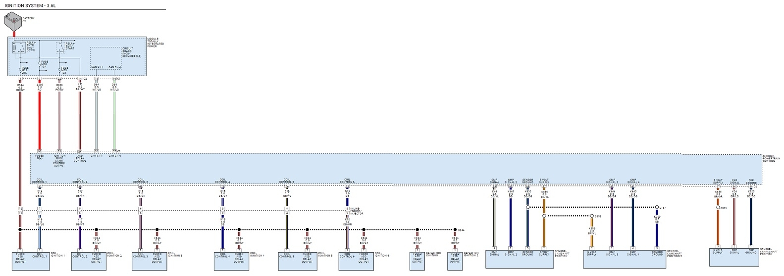
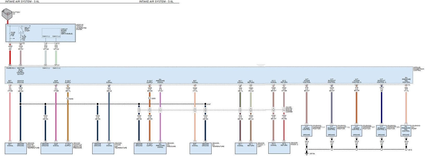
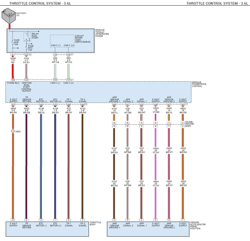
If you want to access an online service manual, we use AllData. Shops pay about $1000.00 per year for access to all models. You can buy access to just your one model for about $28.00 per year or $49.00 for five years, last time I checked. I can post diagrams for you too, but they purposely made copying them difficult. To get acceptable clarity, I have to expand them, then copy them in multiple pieces, and then group them together to make them readable. I do this all in MS Word, a typing program where I can add callouts and arrows. I know there's easier ways, but this lets me manipulate them later, if needed. From there I copy them into MS Paint where they can be saved in a JPEG format that can be uploaded. I did that for all of your fault code diagnostic steps until 6 a.m. this morning. By using MS Paint, I have to do them all one page at a time, so some have over 20 pages to read through.

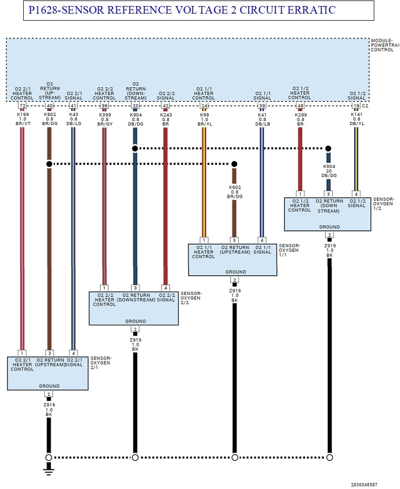
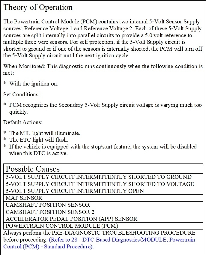
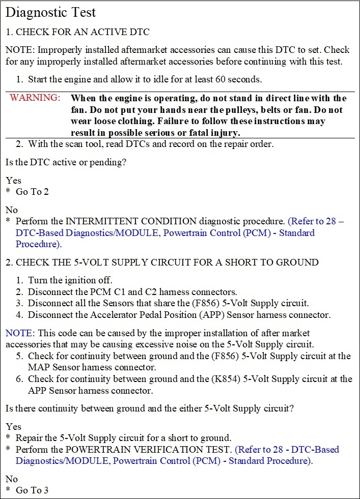
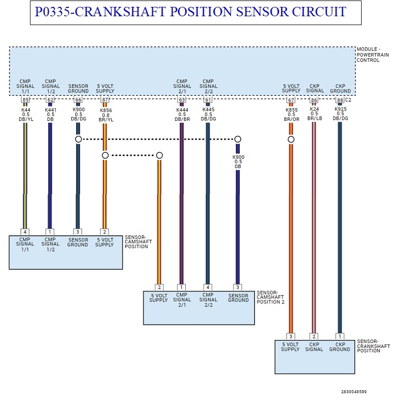
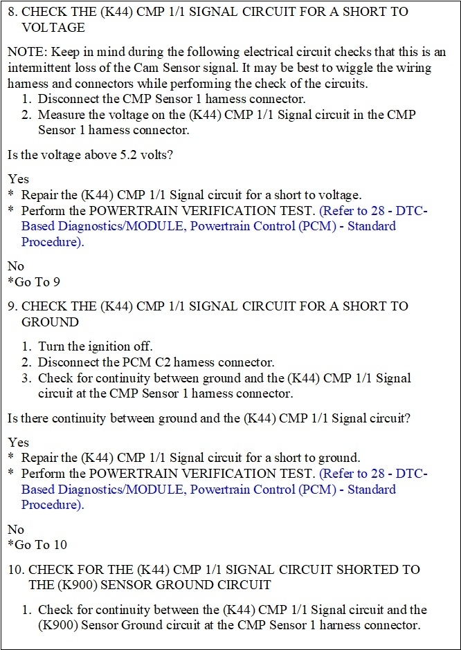
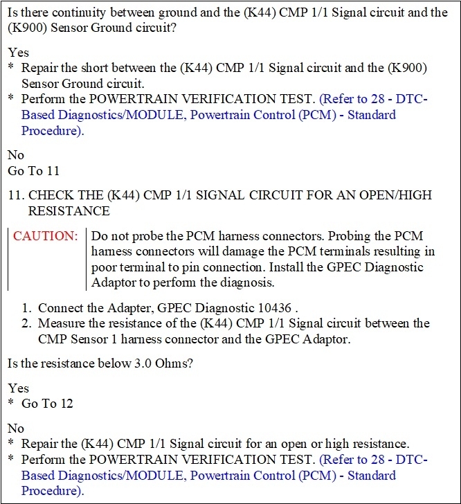
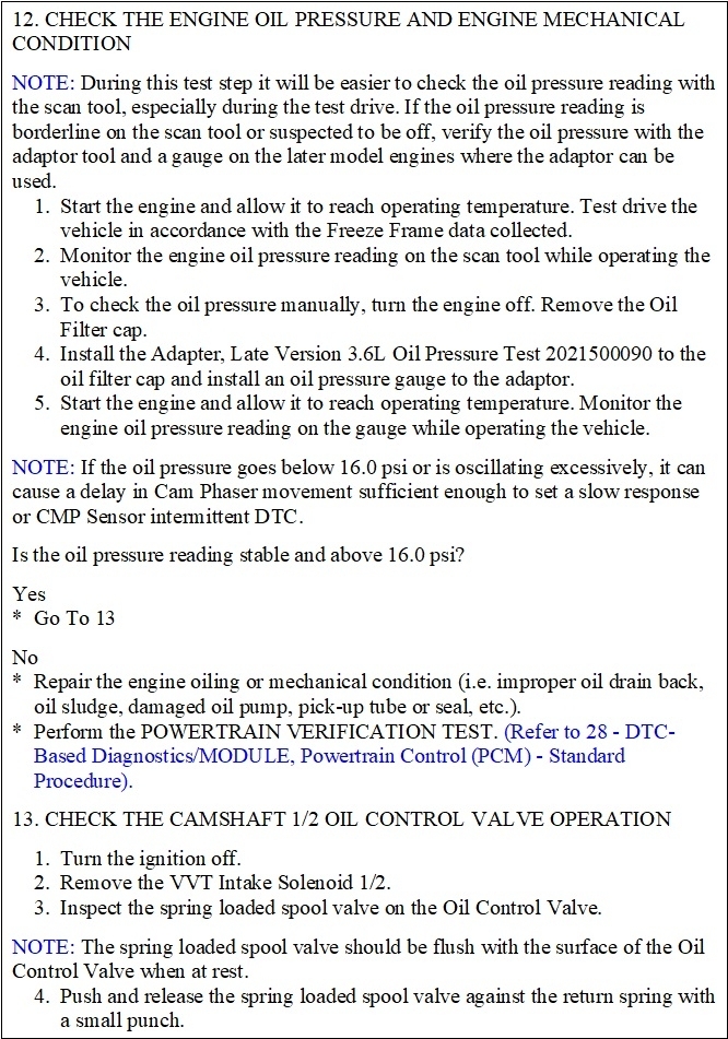
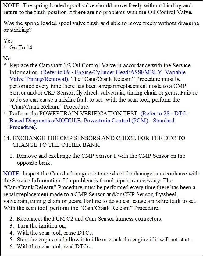
One thing that made this easier was the procedure for diagnosing three of the codes, while 21 pages long, are almost identical. I had to read through them and just change a few numbers here and there. I'm going to post the steps for one of them for now. Since almost everything is the same, if you find the cause of this problem with the steps for one code, you'll likely solve all the other codes at the same time.

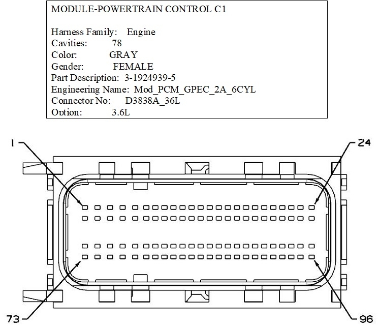
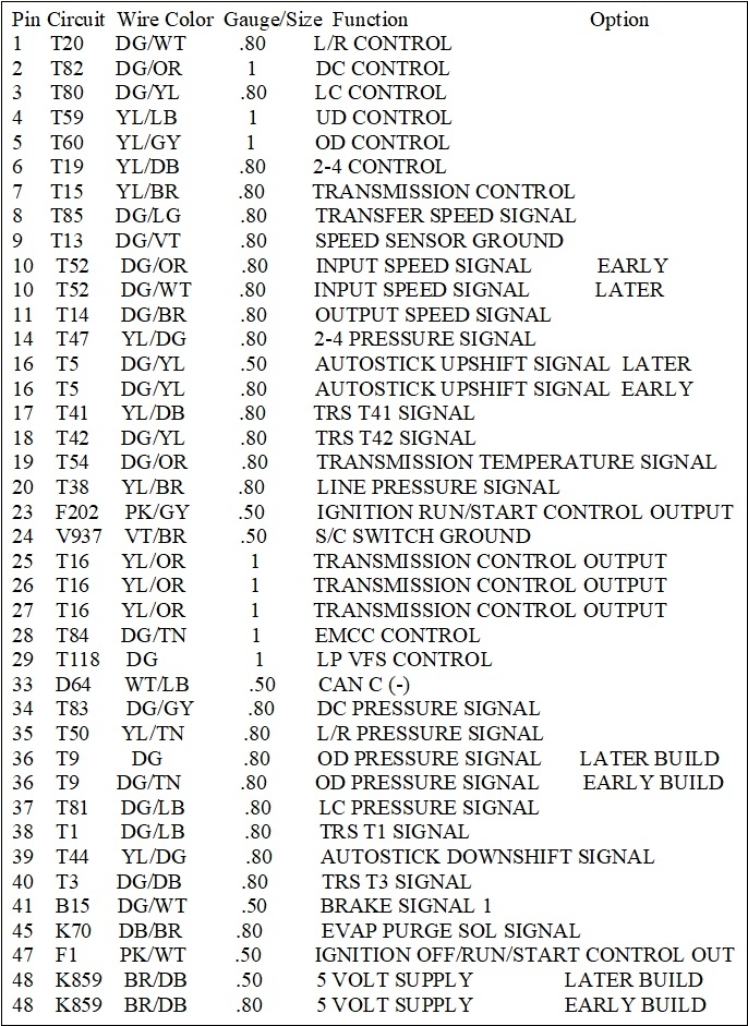
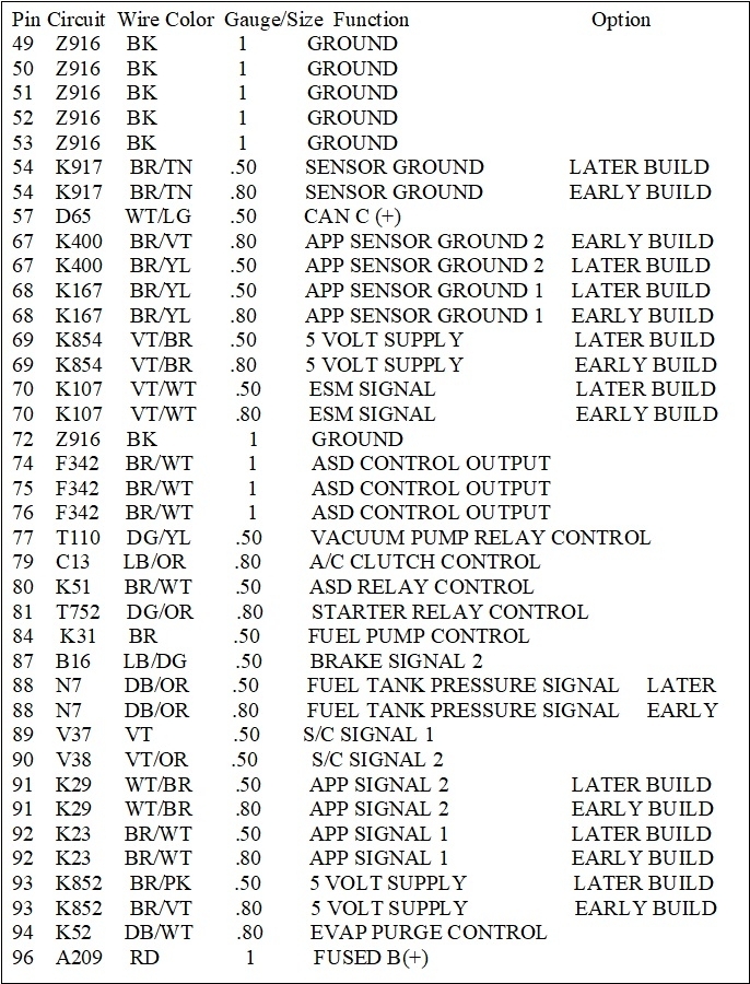
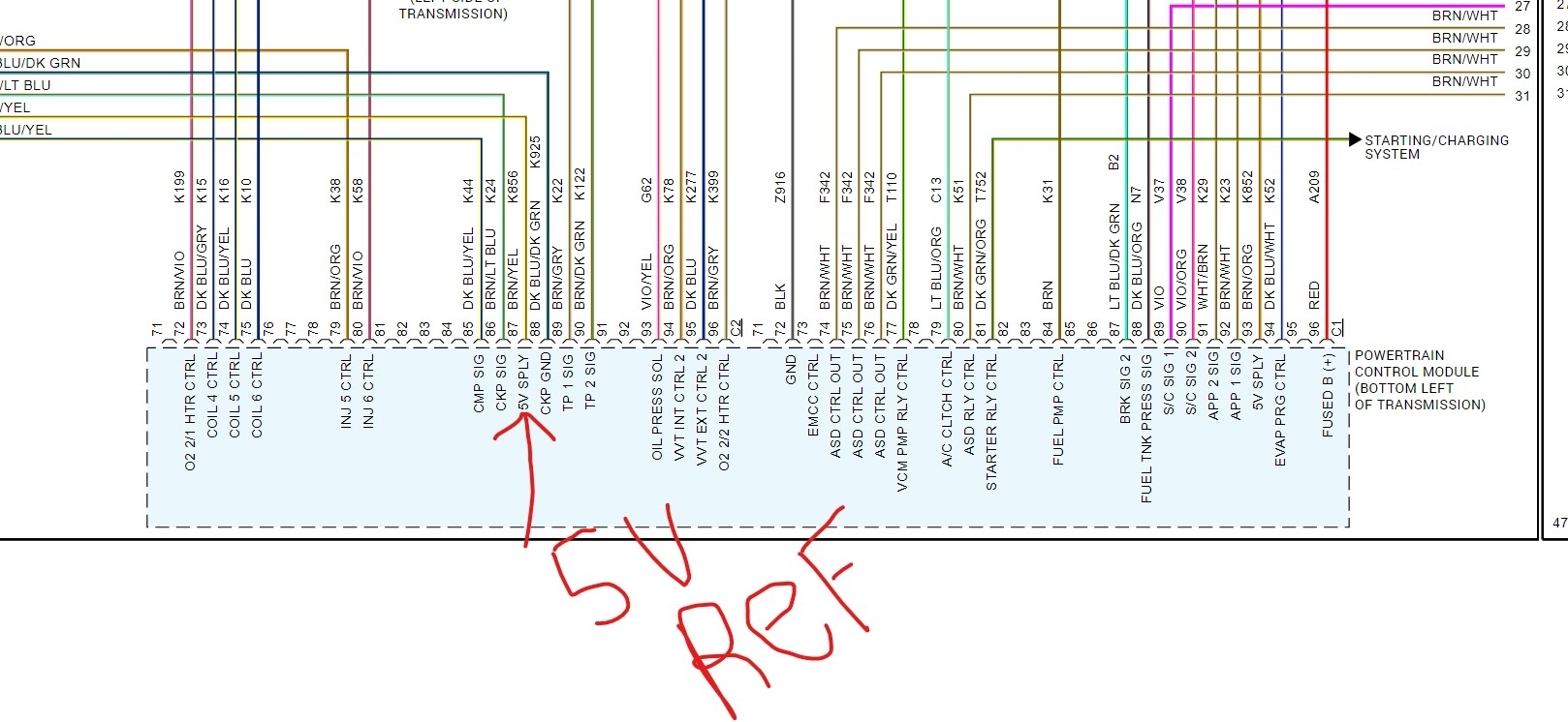
Steve alluded to something I was never taught in my TV Servicing class, but I did learn it years later. That is when it comes to a "black box", meaning a module, a computer, or an integrated circuit where you don't know what's inside, you need four things for that box to work. You gotta have all the power supplies, all the grounds, nothing is open or shorted on the outputs, then you'll get the proper outputs if the box is okay. It's common to have four 12-volt feeds to the Engine Computer. One is constant to maintain fuel trim numbers and learned sensor personalities in memory. One is switched on with the ignition switch to turn it on. The computer turns on the automatic shutdown, (ASD) relay which powers up the injectors, ignition coils, and a few other circuits including one that goes back to the computer as proof it got turned on. I don't remember where the fourth one came from.

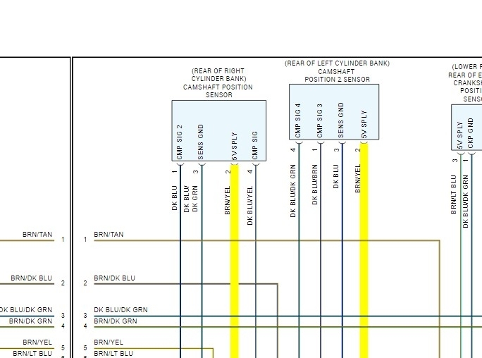
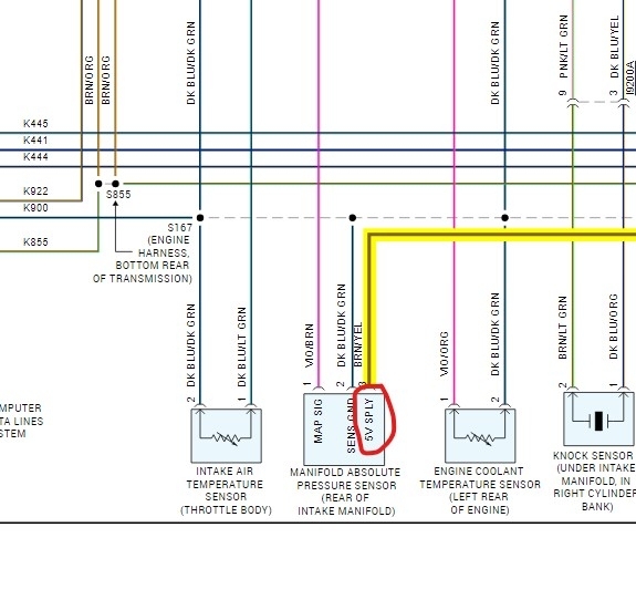
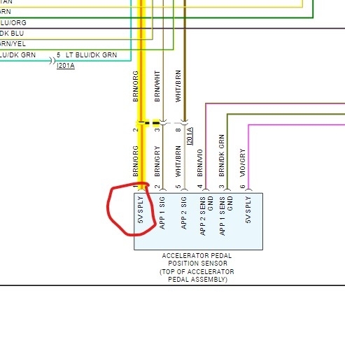
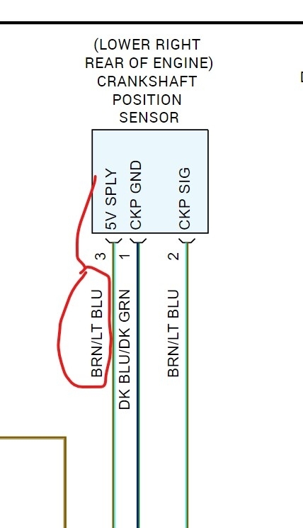
I already described the multiple ground wires. It appears you already verified the 5-volt sensor supplies and the grounds are okay. I would have suggested the same thing Steve said about the unlikelihood of so many failed sensors, and to look for what they have in common.

One thing that didn't come up yet is problems with the TIPM, totally integrated power module, (under-hood fuse box). Most people think those cause a lot of trouble, especially from corroded connector terminals on the bottom. I have a friend with a repair / body shop who specializes in rebuilding smashed one and two-year-old Ram trucks. I get called when he has electrical problems, and since he often is the owner of these vehicles, I've had the opportunity to take some of those modules apart. One had an intermittent no-crank problem, and to learn how the system works, I took the TIPM apart. To my surprise, there were only 13 relays, a lot of fuses, but absolutely no electronics inside it. That's why you'll often hear they're "plug and play" with no programming required. It just had seven or eight layers of metal with fingers bent up to form terminals that plugged into other layers. It's easy to find these in a salvage yard. Go by application and check that the same fuses are in the same locations. The modules can have different part numbers.

My reason for bringing this up is you might consider connecting your voltmeter to these 12-volt lines, one at a time, and watch if they hold steady. If one flickers or has dropouts, try wiggling the connectors under the TIPM to see if that changes anything.

Now, to add to the misery, some TIPMs do have a small module plugged in on the driver's side. If you plug the old one into the new TIPM, it will work fine. If you install a different one, some functions do work, so you can drive the truck to the dealership, but they do have to reprogram it to that truck for everything to work.

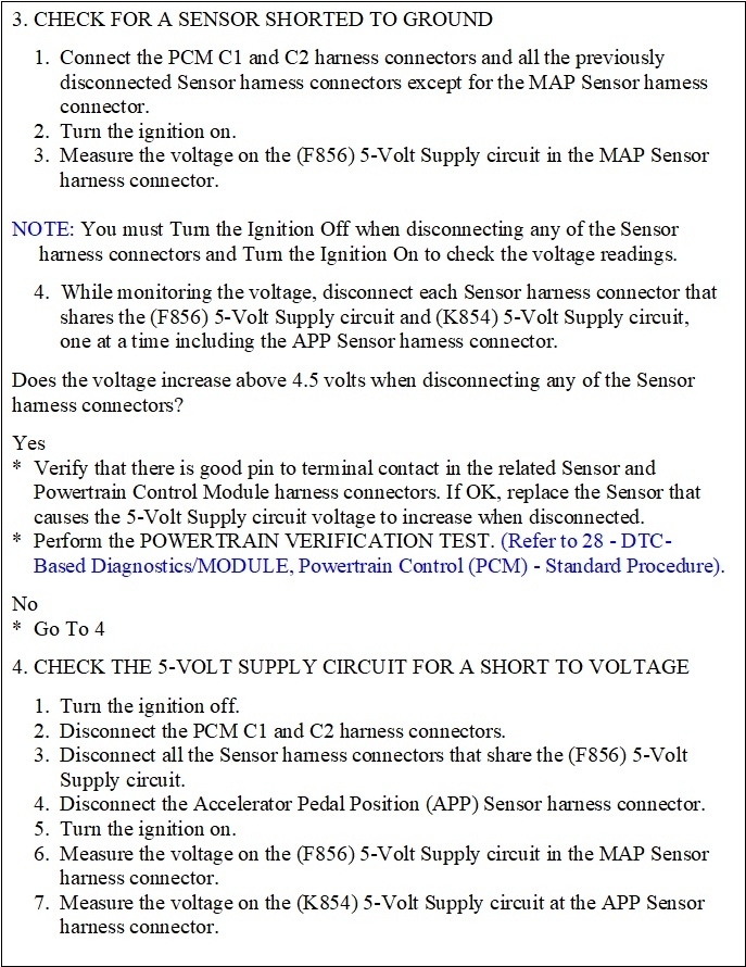
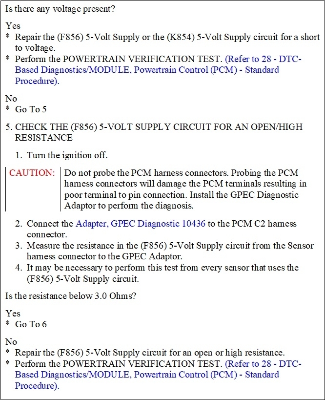
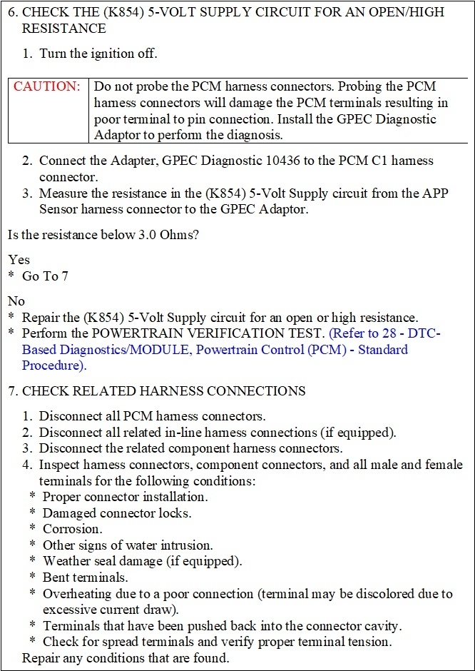
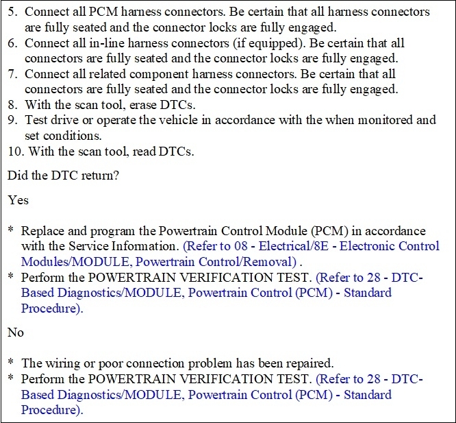
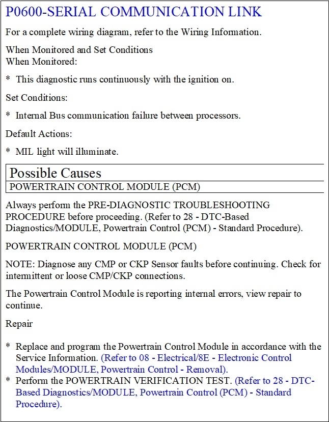
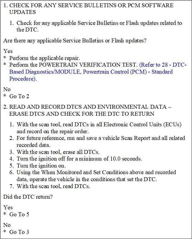
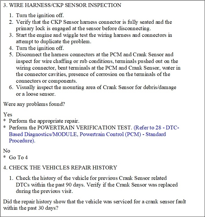
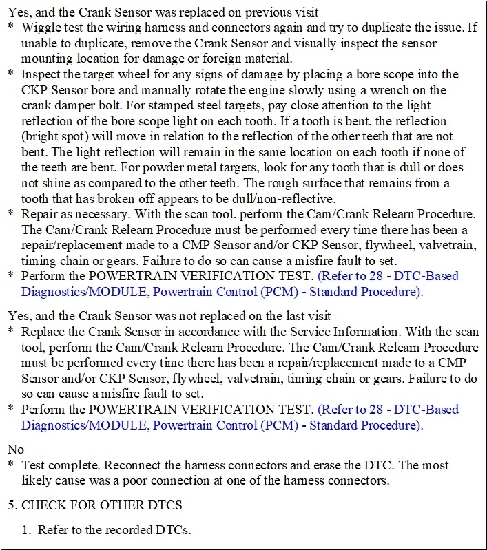
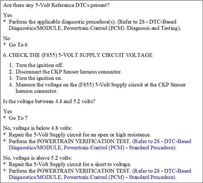
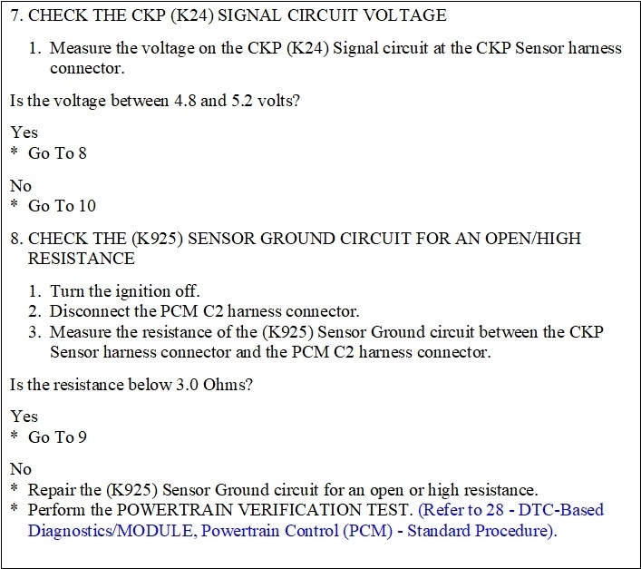
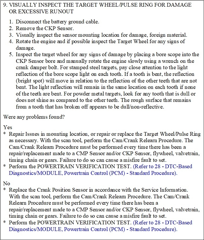
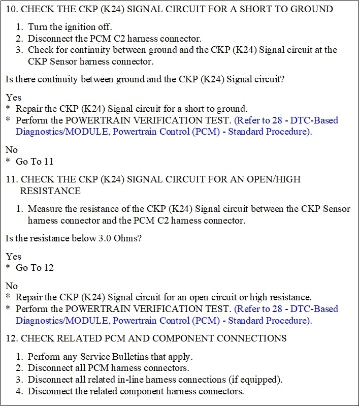
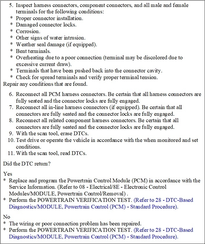
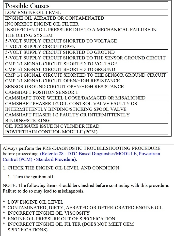
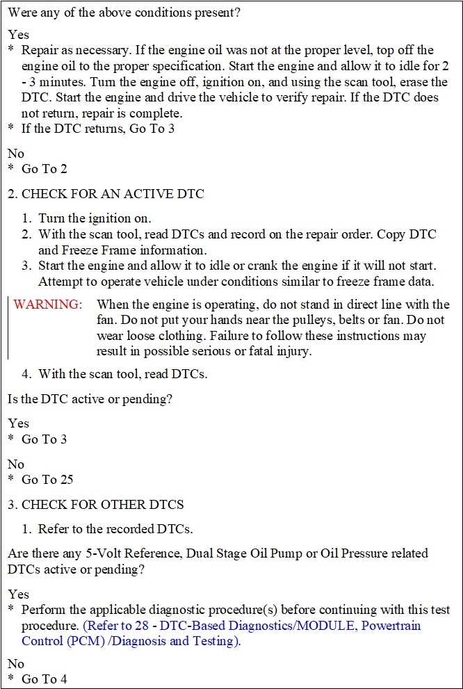
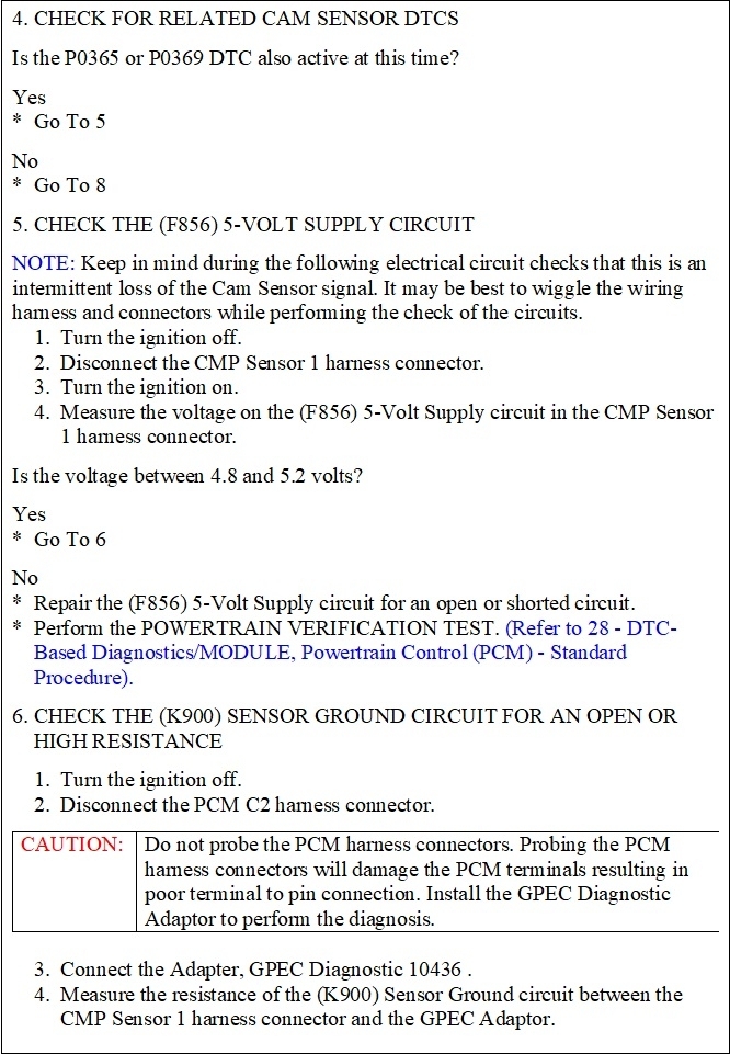
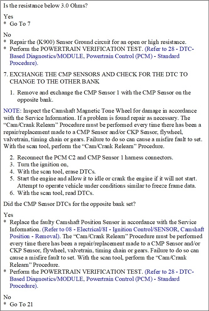
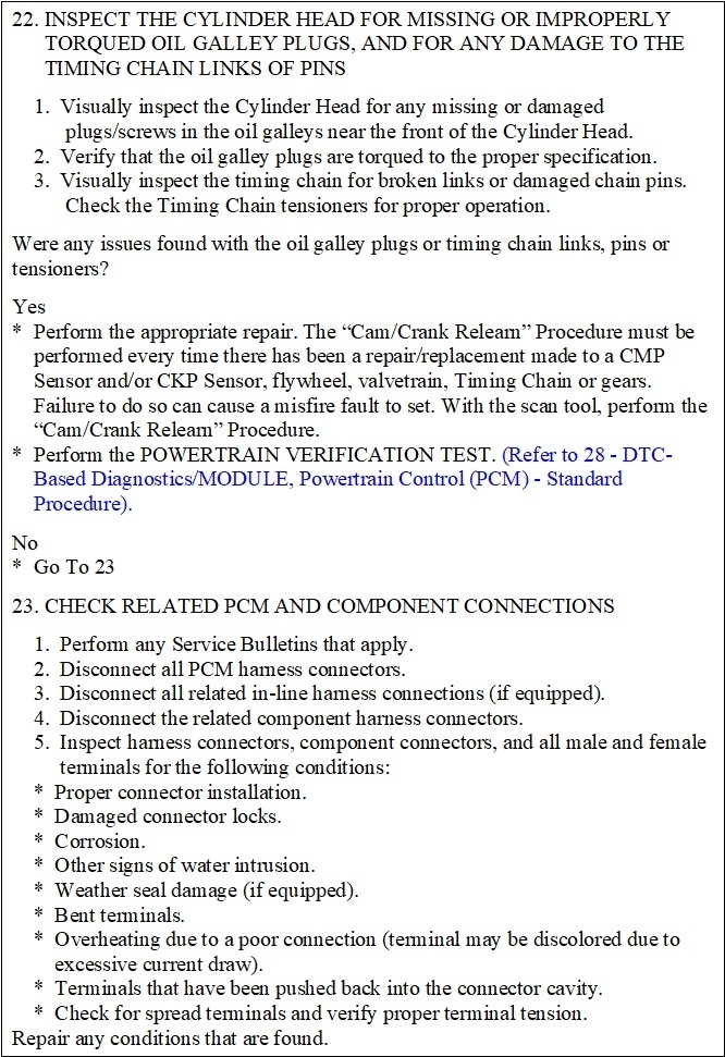
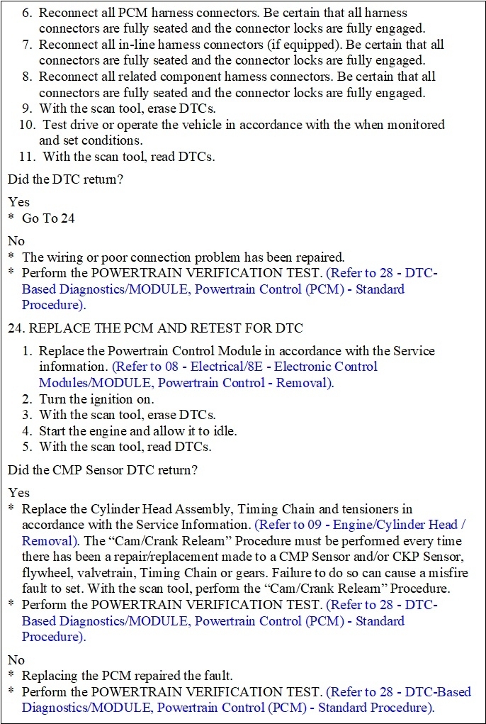
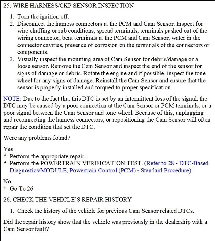
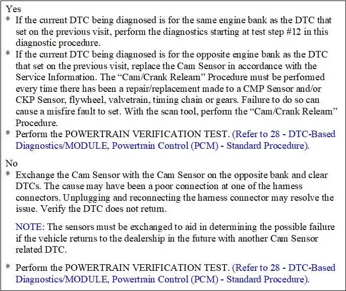
I'm going to split these diagnostic steps up into separate replies to lessen the confusion. Here's the simplest one. It's for code P0600.
Jan 23, 2024 at 5:58 PM
Avatar
CARADIODOC
  • CERTIFIED EXPERT
  • 34,306 POSTS
If these are too small to read, try to copy them into MS Word where it's easy to expand them.

Here's for code P0335.
Jan 23, 2024 at 6:01 PM
Avatar
CARADIODOC
  • CERTIFIED EXPERT
  • 34,306 POSTS
Here's for code P0340. Codes 345, 365, and 390 are almost identical except for the sensor numbers and one wire. The wire referenced can be K44, K441, K444, and, as I recall, K445.
Jan 23, 2024 at 6:08 PM
Avatar
STEVE W.
  • CERTIFIED EXPERT
  • 15,113 POSTS
I just realized I didn't see if you had tested the crankshaft 5 volt reference? That is down on the rear of the engine, if it lacks power the system would use a default strategy. If it has proper power and ground it comes back to testing for correct signal at the PCM using a scope, or the other method of changing the sensor. FYI you also need to do the cam-crank relearn after changing the crank or camshaft sensors, I think that tool can do that.
Jan 23, 2024 at 11:57 PM
Avatar
TIMOTHY HUFF
  • MEMBER
  • 36 POSTS
Steve, you're correct I need to take voltage measurements at every sensor in that group. I didn't check for power at the crankshaft sensor or the accelerator pedal sensor. I will Get back to both. I'm finding it a challenge getting time to dig into this. Be patient, we'll get this!
Jan 25, 2024 at 10:40 AM
Avatar
TIMOTHY HUFF
  • MEMBER
  • 36 POSTS
I'm just curious if the reason it won't start now, or starts briefly, has anything to do with these codes or if something new is Malfunctioning in addition to this. There are no new codes.
Cardio dude thank you for all the time you put into those drawings. I hate to think I got to start checking oil as a possible but diagnosis of this problem. Does that seem likely to the both of you?
With the others being a permanent code, I know that it won't go away until the problem is fixed. But does the engine have to run in order for A permanent code to clear itself?
Jan 25, 2024 at 10:45 AM
Avatar
TIMOTHY HUFF
  • MEMBER
  • 36 POSTS
again wish me luck this shouldn't be this hard.
Jan 25, 2024 at 10:49 AM
Avatar
TIMOTHY HUFF
  • MEMBER
  • 36 POSTS
I asked Google how to clear a permanent code. A Website told me the only way it will clear is when the problem is fixed, and then it is driven for a certain amount of time. So, I can't clear my permanent codes if I can't get the engine running. I wonder if there is more to this than just the sensor circuit. Again, no new codes.
Jan 25, 2024 at 10:52 AM
Avatar
TIMOTHY HUFF
  • MEMBER
  • 36 POSTS
Also, the engine needs to be running in order to do the relearn on the sensors. And yes, my Innova 5610 should relearn the sensors. But again, it needs to be running.
Jan 25, 2024 at 10:53 AM
Avatar
TIMOTHY HUFF
  • MEMBER
  • 36 POSTS
So what's keeping it from running?
Jan 25, 2024 at 10:56 AM
Avatar
STEVE W.
  • CERTIFIED EXPERT
  • 15,113 POSTS
Basic codes explanation. Codes are set when the module detects something that doesn't match the expected parameter programmed into its tables, but they don't normally point to an exact part as many people believe. As an example a circuit code means there is a perceived fault in that circuit. Say that circuit contains 4 items, what do those items share? Are there also codes pointing to one item in that circuit. Say you have a code for the ignition coils, all 6 share a power and ground, but it isn't likely that all 6 failed. However you also have a P0304 (misfire on cylinder 4) so I would check the powers and grounds first, and I discover the power feed is shorted, With the cylinder 4 misfire I'm going to that coil first, Unplug it and the power returns. Replace the coil, clear the codes and no codes return.

Code Types -
Pending code - This is something that tripped a monitor but not a hard fault and until it happens a second time in this run cycle it will not set a current code and turn on the CEL
Current code - This is a code that is a single trip code, IE it sets if the problem only happens one time, or it may be a continuous code fault.

Both of those can be cleared with a scan tool or disconnecting the battery in some cases.

Permanent code - This is also a hard fault code but it stays in the system until it is repaired and the PCM runs that test between one and five times without a fault. These were put in place because of people having a problem and clearing the codes and then showing up at the dealership and complaining the car doesn't run right, and because people would clear the codes to pass an inspection. They cannot be cleared with any form of scan tool, only the PCM can clear them. (These also act as tattle tale codes for the people who install tuners or chips to alter the vehicles performance, they also record any changes made to the PCM programming)

History codes - These are the codes the vehicle has had that have been repaired or were set and cleared on their own.
There are also an entire batch of other codes for the various systems on the vehicle.
P- Powertrain, B- Body codes, U- Communication, C- Chassis plus now that all of the vehicles are gadget laden there are subgroups under each of those.

No rush on getting it done, all of us know what it's like to find extra time.
Jan 25, 2024 at 2:10 PM
Avatar
TIMOTHY HUFF
  • MEMBER
  • 36 POSTS
Well now I know what a permanent code is but how do I get rid of it without the engine running? I get a feeling there's more than one problem here. I got pictures of my scanner and some sort of report from my scanner. I'll be sharing them very soon.
Jan 26, 2024 at 11:33 AM
Avatar
TIMOTHY HUFF
  • MEMBER
  • 36 POSTS
Steve, you asked for live data... These should be close, let me know.
That should be the current state of my truck. Still can't start it.
Jan 26, 2024 at 4:19 PM
Avatar
TIMOTHY HUFF
  • MEMBER
  • 36 POSTS
I also found out how to generate a report. This was generated after Voltages okay. and just after it started to run for about 10, then stalled. See if you guys can do anything with this info.
Jan 26, 2024 at 4:22 PM
Avatar
STEVE W.
  • CERTIFIED EXPERT
  • 15,113 POSTS
Until it is running and can run the tests the permanent codes cannot be cleared. The PCM has to run the tests and see that the system is running correctly. Once it completes that test a few times it will then clear the code. But you can ignore the permanent codes for now. Deal with pending and current codes and repair those faults.

Using the live data you posted, the throttle pedal isn't the issue. The way it works is like many 3 wire sensors. You apply a reference voltage to one side (5 volts in this case) and a ground to the other. Then the voltage changes as the sensor moves. Sort of like a volume control. For the throttle pedal there are two connected in reverse. One voltage rises as the other falls. The PCM and throttle motors use that voltage to determine where to move the throttle blade in the throttle body.

OK looking at the reports. Go find the purge solenoid on the right-side strut tower next to the firewall and replace it or at least block the hose to it from the tank. If that valve is stuck open the truck will act like it is severely flooded. That could be the cause of it not starting.
The valve has one electrical connection (top) then two hose connections. Simply swap it with new. Now hold the throttle fully to the floor and crank the engine over a few seconds. Let up and try it, see if it starts now.
Jan 26, 2024 at 5:55 PM
Avatar
TIMOTHY HUFF
  • MEMBER
  • 36 POSTS
Thank you for taking the time! I won't be able to get to it until Monday, but I have a direction. And it's acting and smelling like a flooded engine. Anything else comes to mind for when I work on it Monday. I didn't want to ask one more question, did you like the Innova 5610? I was very disappointed when I received it my model, they removed the WIFI connection leaving only Bluetooth. They kind of upset me greatly. I wanted to be able to work from my Inside computer to my car. Besides I find nothing other than a report from that Repair Solutions2 software...
Jan 26, 2024 at 6:35 PM
Avatar
STEVE W.
  • CERTIFIED EXPERT
  • 15,113 POSTS
That tool looks reasonably good for a DIY level tool, without having it in my hands though I can't comment much. The manual for it is a bit lackluster but that's common. I basically use a small code reader to get a quick idea of what codes are there before I accept a job. Then I have 3 other OE level scan tools plus a couple factory tools to really dig into the systems with full bidirectional control. As an example of bidirectional control, say your van comes to my shop, and you are showing the same codes. I can go into EVAP and cycle the purge solenoid while listening to it, I don't hear it, so is it the circuit or the valve? I can then unplug it and connect a test light or my U-Scope and then use the scan tool to change the duty cycle on the control voltage to the valve. If I see the light or scope reacting the way they should, it's a bad valve, and so far, I've unplugged one connector! Same things can be done to look at the can and crank sensors as well as many other sensors.
I can find something similar in the data display on your tool but can't tell if you have the testing to do it. If you look at your images there is one that says Commanded Evaporative Purge 0%. That means it should be fully closed. I do see it shows it can do a purge test, but it doesn't say which parts it can test and most of them require a running engine to create a vacuum to do the testing.
Jan 26, 2024 at 7:23 PM
Avatar
TIMOTHY HUFF
  • MEMBER
  • 36 POSTS
The new EVAP Canister did not help. The old one was not stuck open. It is exactly the same just barely trying to start blowing out lots of white smoke and smelling like it's flooded (Smells more like WD40 than gas ). Could be something stupid like bad gas? Oh yeah and my oil looks like coffee color. It's not that far past needing to be changed. I will do further diagnostics if you have any suggestions they would be greatly appreciated.
Jan 31, 2024 at 11:49 AM
Avatar
CARADIODOC
  • CERTIFIED EXPERT
  • 34,306 POSTS
At the dealership in the mid '90s, we had two cars come in on tow trucks in one day, both with crank / no-start conditions. On the first one, after the drivability expert beat his head against the wall for a day and a half, he bled off a sample of gas, threw it on the floor, and tossed a lit match on it. The "gas" put the match out. Found out both owners bought gas from the same station the day before. I assume my coworker drained both tanks and put good gas in. I DO know it didn't take so long to figure out the second one.
Jan 31, 2024 at 5:06 PM