it still wants to overheat?

2005 CHEVROLET CLASSIC
191,589 MILES • 2.2L • 4 CYL • 2WD • AUTOMATIC
Avatar
TRAVIS BUTLER2
  • MEMBER
  • 83 POSTS
Okay I've replaced the coolant temperature sensor I've done a coolant flush on it and still it doesn't want to kick the fan on to cool it down I've main line to the fans to the battery it comes on I ordered a relay haven't got that in quite yet but it still wants to overheat what could possibly be the problem it happened on a trip back from Curlew Washington to Yakima Washington
May 2, 2023 at 9:29 PM
Advertisement
Avatar
BRENDON S
  • CERTIFIED EXPERT
  • 653 POSTS
Good morning, TRAVIS BUTLER2,

I have included a wiring diagram for the cooling fan circuit as well as a fuse box diagram. There are 2 fuses (marked in yellow) and 3 relays (marked in green).

I would check the fuses first with them still installed with a test light. Here is an article that will show you how to do that:
https://www.2carpros.com/articles/how-to-check-a-car-fuse

Next, I would test all 3 relays. Here is an article that will show you how to do that:
https://www.2carpros.com/articles/how-to-check-an-electrical-relay-and-wiring-control-circuit

Both articles have a lot of great information in them.

I have added an image of a typical 4 wire relay and a 5-wire relay because you have both in this circuit.

This time I would take a test light and hook it to battery negative. Your relays should have wiring diagrams on them. Remove the relays one at a time and see if you have power on terminal 30 on fuse box for all 3 relays.

If the fuses were good, this final test will tell us everything from the fuses to the relays are good.

Let me know what you find from these 3 tests, and we can go from there, testing the rest of the circuit.

Thank you,
Brendon
Jun 7, 2023 at 5:48 AM
Avatar
TRAVIS BUTLER2
  • MEMBER
  • 83 POSTS
Okay, I checked fuses they are ok I replaced 12 relay others haven't been able to check yet. I also replaced water pump and thermostat it still wants to overheat.
Jun 8, 2023 at 12:04 PM
Advertisement
Avatar
TRAVIS BUTLER2
  • MEMBER
  • 83 POSTS
I forgot to mention it don't leak and coolant isn't going into oil.
Jun 8, 2023 at 12:05 PM
Avatar
BRENDON S
  • CERTIFIED EXPERT
  • 653 POSTS
Hello TRAVIS BUTLER2,

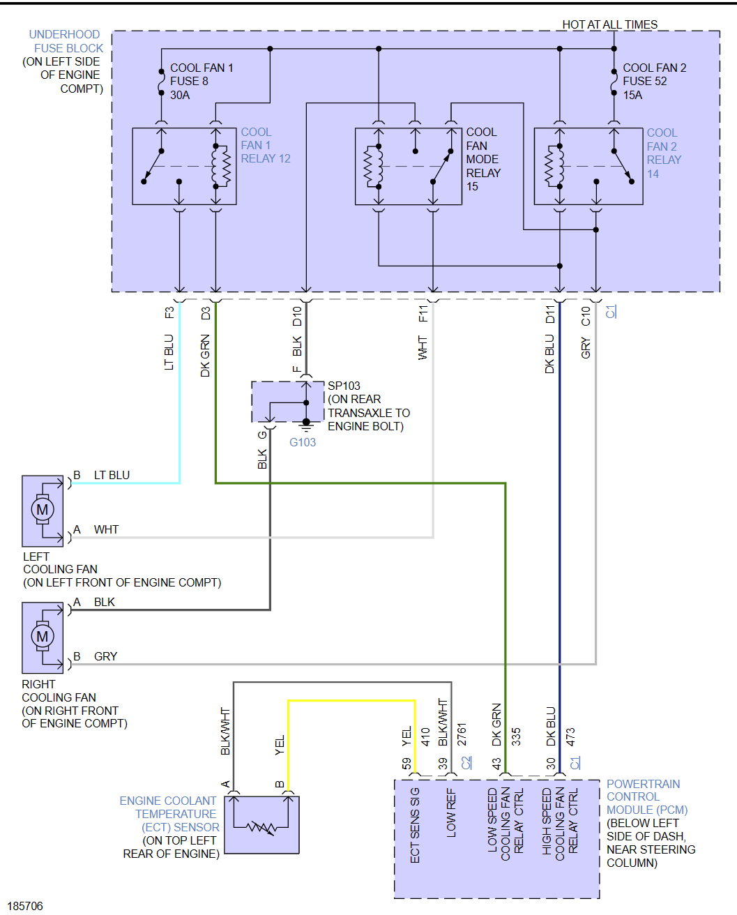
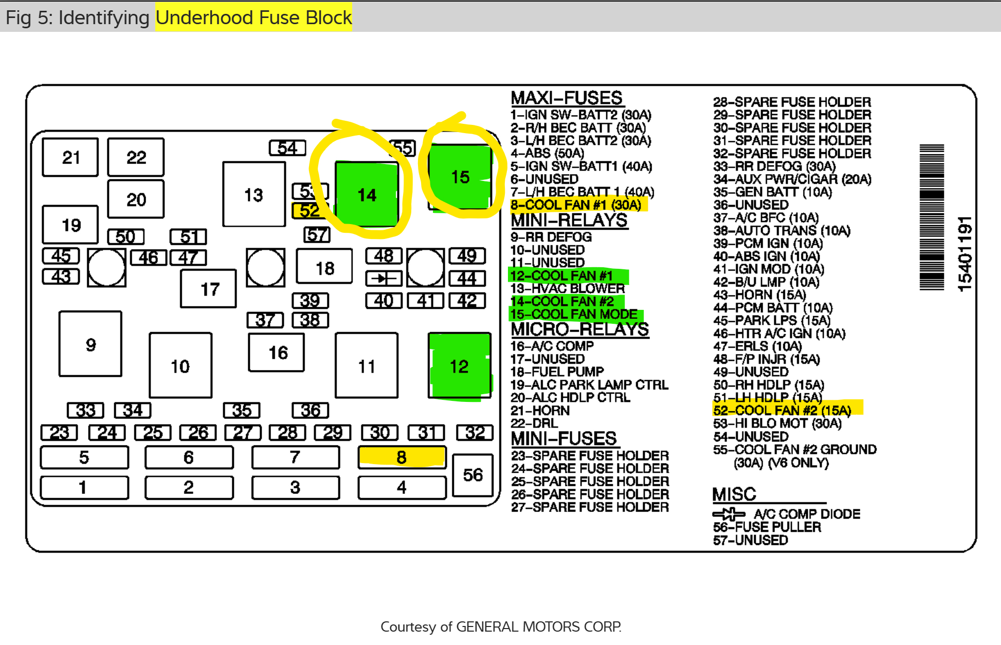
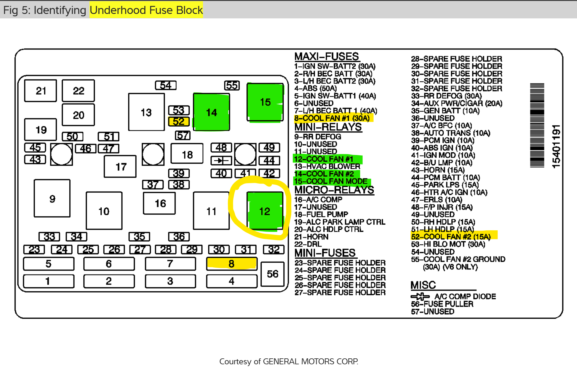
Looks like relays 14 and 15 are the same, at least on my end. I would try switching them and see if the fans come on.

If nothing changes, I would test the relays to make sure they are good and if so put them back for now.

You can also test the ECT circuit to make sure it is functioning properly. I know you replaced the sensor, but the reading depends on a low voltage reference from the PCM. If the PCM isn't getting the right signal, because it isn't sending out the right voltage in the first place, it will not turn on the fans.

The best way to check this is with a scan tool, do you have one? If so, you can bring up the engine temperature and the signal voltage.

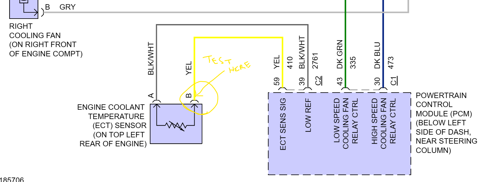
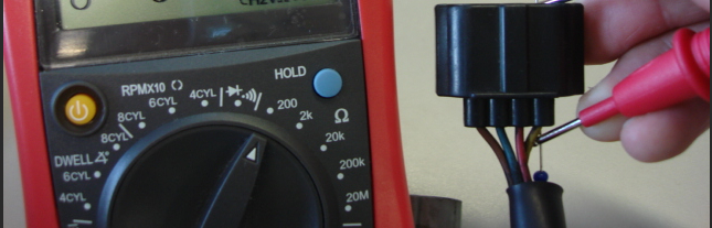
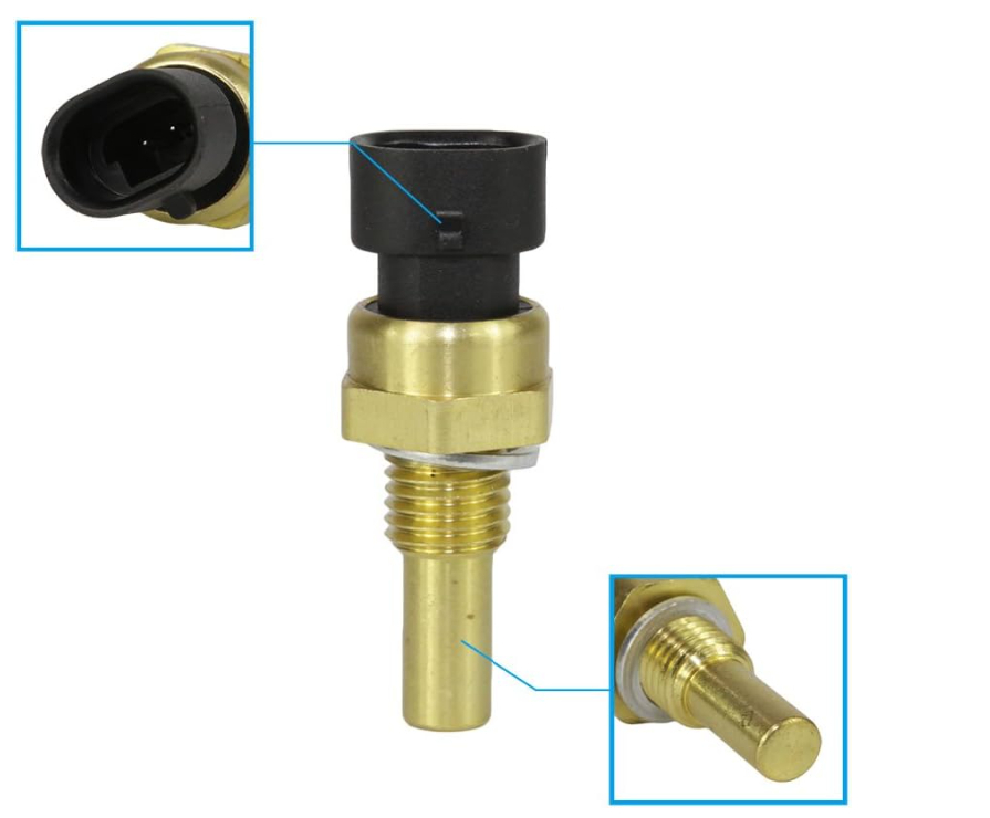
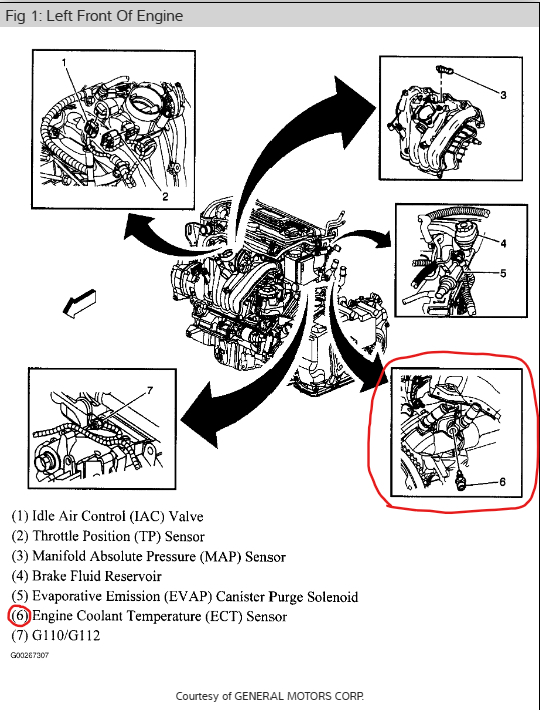
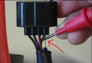
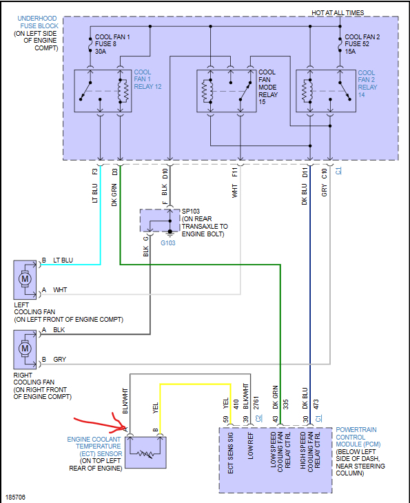
If not, another way is to use a multimeter. There are 2 wires coming out of the ECT Sensor. The yellow wire is the signal wire that is being sent to the PCM. We want to measure the voltage on the wire. I have attached a wiring diagram for you.

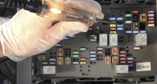
You will need to back probe the connector with a pin on the yellow wire.
Put black lead on ground on battery negative and red lead on the pin. You should have a signal voltage of roughly 0.5 to 4.5 volts. You should never see 0 or 5.0volts.

This sensor is simply a resistor. 5 volts is sent from the PCM to the sensor. The sensors resistance increases as temperature increases, which lowers the voltage signal the PCM receives. The lower the signal wire voltage the hotter the vehicle should be.

This will tell us the PCM is sending the right voltage to the sensor and the right signal to the PCM. Key needs to be on but not started.

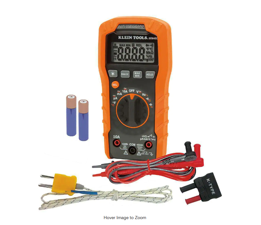
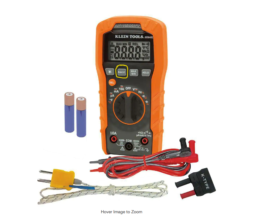
I will add a picture of the multimeter I have. If you don't have one you can pick one up at the auto parts store or Home Depot has them too. That's where I got mine from.

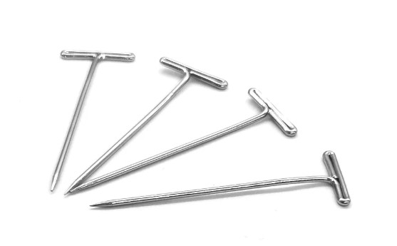
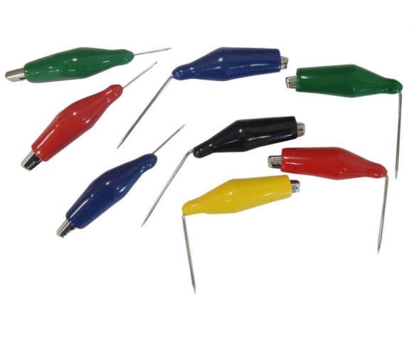
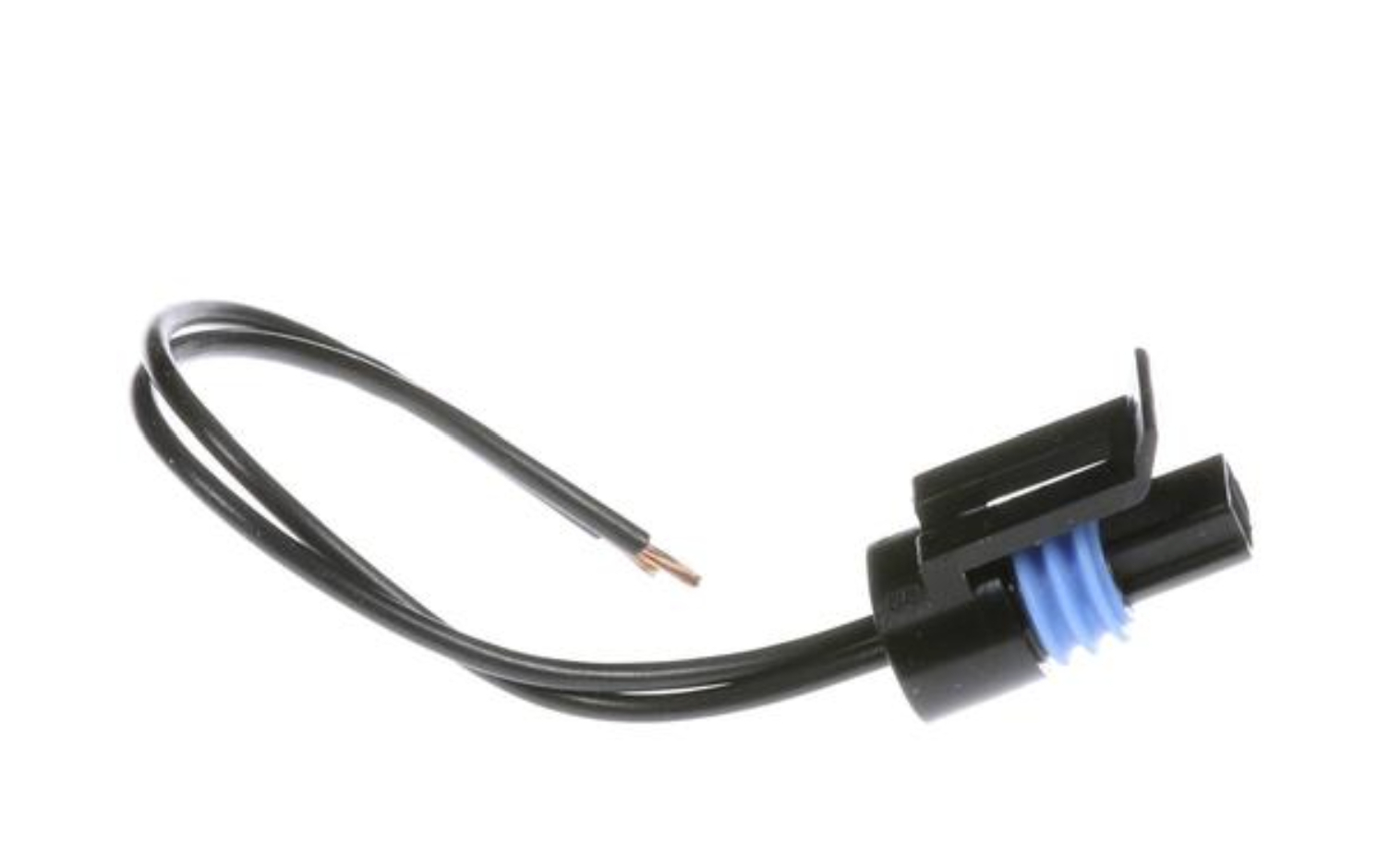
I am also adding the pins I use to back probe connectors. You can get them at Walmart in the craft section. You may also use a sewing needle and bend the end 90 degrees so you can push it into the connector.

So, I would try switching 14 and 15 and see if anything changes and check the voltage signal from the sensor on the yellow wire. Then test the other 2 relays to make sure they are good.

Here is a good article about a multimeter that will help:
https://www.2carpros.com/articles/how-to-use-a-voltmeter

Here is a video on how to back probe correctly:
https://youtu.be/Spy8AXlxVT0

Then we can rule out all of those as possible issues.

Please let me know if you need any help testing.

Thank you,
Brendon
Jun 8, 2023 at 1:10 PM
Avatar
TRAVIS BUTLER2
  • MEMBER
  • 83 POSTS
Yes, I have a scan tool. what exactly am I supposed to look for I'm in the live data powertrain?
Jun 10, 2023 at 2:38 PM
Avatar
BRENDON S
  • CERTIFIED EXPERT
  • 653 POSTS
Hello TRAVIS BUTLER2,

You are going to want to pull up the engine coolant temperature and see if you can get an ect voltage reading as well.

Also see if you have an option to turn on the cooling fans and see if it will let you turn them on manually.

Did you try switching relays 14 and 15 and see if that changed anything or get around to testing them?

Thank you,
Brendon
Jun 10, 2023 at 4:52 PM
Avatar
TRAVIS BUTLER2
  • MEMBER
  • 83 POSTS
One is 4 prong the other is 5 n it won't let me turn them on manually other than how I turn them on with a toggle switch and I don't have the stuff to test them atm.
Jun 12, 2023 at 5:16 PM
Avatar
BRENDON S
  • CERTIFIED EXPERT
  • 653 POSTS
Hello TRAVIS BUTLER2,

Did your scan tool not have the option, or did you try commanding the fans on, but they didn't come on?

You should have two 5 prong relays and one 4 prong relay. Can you verify this for me?

I am re-sending the fuse box diagram, 14 and 15 should be both 5 prong.

I just want to make sure my info is correct.

If they are, and look exactly the same, try switching the two and see if the fans will come on. Sometimes a good way to find a bad relay is by switching it with one that is exactly the same.

Also, where you able to pull up a voltage for the ECT with your scan tool? If so, what did you get key on engine off? What about with it running and up to temp? What did you get for voltage?

Thank you,
Brendon
Jun 12, 2023 at 5:43 PM
Avatar
TRAVIS BUTLER2
  • MEMBER
  • 83 POSTS
K14 is a four-prong 15 is 5 prong I tried switching 14 with the HVAC blower and 15 with the one that I bought when I hooked up my scan tool it don't have that option but the voltage with the motor off cold says o2sb1s1 0.445 volts it won't tell me the ECT voltage it just says 77°, but that's the only one that tells me volts on my scan tool and that's in through the live data section I haven't tried it getting it up to temperature yet to see what the voltage is.
Jun 13, 2023 at 6:11 AM
Avatar
TRAVIS BUTLER2
  • MEMBER
  • 83 POSTS
When I switched the relays nothing happens still.
Jun 13, 2023 at 6:11 AM
Avatar
BRENDON S
  • CERTIFIED EXPERT
  • 653 POSTS
Hello TRAVIS BUTLER2,

Okay. So, you only have 2 relays? So, the diagram I sent you isn't what your fuse box looks like?

Can you send me a photo of the fuse/relay panel you have? I keep pulling up diagrams with 3 relays for this vehicle.

I need to make sure my information is accurate so I can help you.

If you can snap a couple good photos for me really quickly and send them over so I can compare it to my information, I would really appreciate it.

Can you verify your vehicles details for me also?
I have:
2005 Chevy Classic with 2.2L, Front Wheel Drive, Automatic

Is this correct?

Sorry for the confusion and thank you for your patience.

Thank you,
Brendon
Jun 13, 2023 at 6:59 AM
Avatar
BRENDON S
  • CERTIFIED EXPERT
  • 653 POSTS
Hello TRAVIS BUTLER2,

Also getting it up to operating temperature and seeing what the scan tool is saying the temperature is, is definitely a good idea.

We know the sensor is good cause it's new. But if there is something going on that is dropping the reading when the PCM gets the info, like extra resistance in the circuit or the computer isn't supplying the full 5-volt low reference signal, the computer isn't going to turn on the fan because it will think it is cooler than it actually is.

So, I would definitely warm it up and see what it says and send some pics of the fuse box if you can.

Thank you,
Brendon
Jun 13, 2023 at 7:18 AM
Avatar
TRAVIS BUTLER2
  • MEMBER
  • 83 POSTS
Okay, I got the key on engine off and it's at 180° but it's still saying 0.445 volts for the 02sb1s1 and my phone is being retarded it won't upload a video or picture, it's saying that it's the wrong format.
Jun 13, 2023 at 10:22 AM
Avatar
TRAVIS BUTLER2
  • MEMBER
  • 83 POSTS
But my fuse box looks exactly like the one you sent me it's just number 14 is a four-prong and 15 is a five.
Jun 13, 2023 at 10:23 AM
Avatar
BRENDON S
  • CERTIFIED EXPERT
  • 653 POSTS
Hello TRAVIS BUTLER2,

Okay. That's too bad your phone won't send them. It must not be a supported file type. No big deal we will work around it.

O2sb1s1-That sounds like the data pid for upstream O2. If so that data isn't going to help us. Key on you should have voltage there. When running if that is the upstream O2 then it will fluctuate between 0.1 to 0.9. I would remove this data from your live stream if you can, to avoid confusion.

Does your temperature gauge on the car match the scan tool?

See if you can get the temp up higher.

When you tried to command on the fans, did the scan tool not have the option or does it have the option, but it wouldn't work? Can you clarify this for me?

Do you have this circuit hook back up the way it was or is it still connected to the battery?

If it is still hooked to the battery the fans aren't going to kick on. You will need to hook it back up the way it was. But let's find this 3rd relay if we can.

You said your fuse box is the same, but you say you only have 2 relays; you should have 3.

I have added the diagram again. Do you have a relay in position 12 that I have circled?

I need to know so we can move on because that is the relay for half the circuit.

We need to check the control side of this circuit. You going to have to get it up to temp which should be right around 210 degrees Fahrenheit. Fans should turn on around 195 degrees Fahrenheit. At this point the PCM should be commanding on the fans.

If it is then we will have power on terminal 87, more likely on the low side first. Which is the relay number 12.

So, I need to know if you have relay number 12. Please compare diagram and see if that relay is there.

Thank you,
Brendon
Jun 13, 2023 at 11:29 AM
Avatar
BRENDON S
  • CERTIFIED EXPERT
  • 653 POSTS
Hello TRAVIS BUTLER2,

What we know:
The fans operate, so their good.
Fuses checked, their good.
ECT replaced, so that's good.
So far, we know at least one relay is good.

So, the last part of the puzzle is a wiring issue. To check for wiring issues, we need to isolate and test all parts of the circuit and eliminate them one at a time.

If on all relays we have power at terminal 30 on each relay position. This terminal should have power at all times.

Terminal 86 on each relay should have power when the PCM gets the signal from the ECT and once it hits a certain temperature, will put power to this terminal. So when the vehicle reads on the scan tool above about 195 degrees it should turn on at least one of those relays at terminal 86.

So, we will use a test light to battery negative and see if any relays have power at terminal 86.

Also, when you wired the fans, I am assuming you took power and ground to battery?

Thank you,
Brendon
Jun 13, 2023 at 11:43 AM
Avatar
TRAVIS BUTLER2
  • MEMBER
  • 83 POSTS
I hooked positive to battery ground to frame went to 2 way toggle switch with inline fuse.
Jun 13, 2023 at 9:03 PM
Avatar
TRAVIS BUTLER2
  • MEMBER
  • 83 POSTS
N I did get it up to 213 degrees still no fan
Jun 13, 2023 at 9:05 PM
Avatar
BRENDON S
  • CERTIFIED EXPERT
  • 653 POSTS
Good morning, TRAVIS BUTLER2,

Are the fans still hooked up to the cooling fan circuit and you just ran additional wires from fans to battery and frame or are they completely disconnected from the cooling fan circuit?

Also do you have a multi-meter?

Thank you,
Brendon
Jun 14, 2023 at 4:56 AM
Avatar
TRAVIS BUTLER2
  • MEMBER
  • 83 POSTS
Sorry, I didn't see that u replied until I searched for the messages but yes I have a multimeter and the fans are still hooked up to the circuit I just added extra wires go from battery to inline fuse to toggle from there to fan n ground goes to frame but I forgot to mention that if I have the fan on n try turning on the ac it will blow my inline fuse idk if that helps at all.
Jul 22, 2023 at 8:40 AM
Avatar
TRAVIS BUTLER2
  • MEMBER
  • 83 POSTS
I also replaced a 4 prong and the other 5 prong relays.
Jul 22, 2023 at 8:41 AM
Avatar
BRENDON S
  • CERTIFIED EXPERT
  • 653 POSTS
Hello TRAVIS BUTLER2,

Hey good to hear from you. I was wondering what happened to you.

Let me look over our previous conversation and information, then we will see what we can come up with.

Thank you,
Brendon
Jul 25, 2023 at 9:15 AM
Avatar
BRENDON S
  • CERTIFIED EXPERT
  • 653 POSTS
Hello TRAVIS BUTLER2,

So, since you have a multimeter, let's check and see if the Engine Coolant Temperature Sensor is getting the 5-volt reference from the PCM.

You will need to test right at the connector with it plugged in. We are going to back probe the connector with a needle or something similar.

I have added some examples of so things you could use to do this.

You are going to carefully insert a pin or a needle on the black wire with the white stripe, also referred to as a tracer. (See image)

Once the pin is in position, turn the key on.
-Black lead to batt negative
-Red on pin we just put in.

With the multimeter on Volts DC, see what you get for a reading. You should have right around 5 volts.

This sensor, according to my information, is on the top left rear of the engine. I have added a picture of it for you to make it easier to locate.

Update: I am sorry for some reason it has added images twice and won't let me remove them. Not sure why. I apologize if this causes any confusion. Please let me know if you have any issues viewing them.

Let me know what you find.

Thank you,
Brendon
Jul 25, 2023 at 3:28 PM
Avatar
TRAVIS BUTLER2
  • MEMBER
  • 83 POSTS
Okay, I just tested it I'm not getting any reading off the black wire I am getting 1.2 off of the other wire but I am not getting any reading I tested it when it's cold does it have to be warm.
Aug 14, 2023 at 7:55 AM
Avatar
BRENDON S
  • CERTIFIED EXPERT
  • 653 POSTS
Hello TRAVIS BUTLER2,

Overnight cold, ECT voltage should be within 0.5v of each other. Key on engine running, voltage should be about 1.5v-2.0v at 185-195 degrees Fahrenheit.

As coolant temperature increases, thermistor resistance signal voltage decreases.

If you take red lead and back probe the yellow wire, (ECT Signal) and black to battery ground, you are getting 1.2v with the engine cold?

Is that right?

If you have it, can you send me the part number you used to replace the ECT with? I want to take a look at it and make sure it is correct because it sounds like it is working in the opposite direction it is supposed to.

Thank you,
Brendon
Aug 14, 2023 at 8:42 AM
Avatar
TRAVIS BUTLER2
  • MEMBER
  • 83 POSTS
I haven't replaced the ECM just the temperature sensor, the relays, water pump, and coolant. but yes, that's what I'm getting cold from it off key on.
Aug 15, 2023 at 12:25 AM
Avatar
TRAVIS BUTLER2
  • MEMBER
  • 83 POSTS
I mean ECT not ECM.
Aug 15, 2023 at 12:27 AM
Avatar
BRENDON S
  • CERTIFIED EXPERT
  • 653 POSTS
Hello, TRAVIS BUTLER2,

There seems to be some confusion here on my end. The ECT is the temperature sensor. Engine Coolant Temperature Sensor.

So, I am confused as to what you actually replaced. What temperature sensor and where was it located?

Can you please clarify this for me? If you have a part number for what you have replaced, that would be extremely helpful also.

I have added part of a wiring diagram for the cooling fan circuit. It shows the ECT or Engine Coolant Temperature Sensor. It should be located on the top left (driver's side) rear of the engine.

Can you verify this is where you are testing?

Also, if the numbers you gave me are correct and you are indeed testing the right sensor AND the engine is close to operating temp, then either the sensor is bad or there is an issue with the wiring adding resistance.

This would give the wrong signal to the PCM or Powertrain Control Module will not send the signal to the relays which in turn will not turn on the fans.

Is the temperature on the dash working? Does it seem to match the engine temperature?

Let's start if you could by explaining exactly what sensor it is you replaced. So, we can clear that up.

After that I have a few other tests for ECT sensor.

Thank you,
Brendon
Aug 15, 2023 at 7:29 AM
Avatar
TRAVIS BUTLER2
  • MEMBER
  • 83 POSTS
Yes, that is the sensor that I replaced is the one on the backside of the motor driver side, I just don't know it as ECT. That's the only reason why my end was confused and why I said I didn't replace the ECT, but yet the sensor. I did replace that sensor I do not have the part number; I could possibly look it up. When I tested it, it was first thing in the morning before I even started the car. So, it was completely cold. I can bring it up to temperature and test again with it at temperature but that will be in just a minute.
Aug 15, 2023 at 4:49 PM
Avatar
TRAVIS BUTLER2
  • MEMBER
  • 83 POSTS
This is the part I replaced.
Aug 15, 2023 at 4:56 PM
Avatar
TRAVIS BUTLER2
  • MEMBER
  • 83 POSTS
Okay and that temperature I got .03 volts.
Aug 15, 2023 at 5:04 PM
Avatar
BRENDON S
  • CERTIFIED EXPERT
  • 653 POSTS
Hello TRAVIS, BUTLER2,

Oh, okay, I see. No problem.

Murray is a good brand. Matter of fact I probably would have used that or A/C Delco myself.

So, when it is hot our reading is way lower than it should be on the signal wire. So, the computer doesn't think the fans should be on.

Sounds like the sensor is moving in the right direction so it is reading but not the right amount.

Let's see why.

Try these 2 tests.


1) Out of Range/No Signal Test:

Red lead to black wire by back probing connector with it plugged into the ECT.

Black lead to known good ground. Battery is fine.

Set meter on Volts DC.

With the key on, engine off, voltage should be below 100mv.

Let me know what you get.


2) Then turn the key off and disconnect the ECT sensor.

Red lead to yellow wire (ECT Signal) by back probing connector.

Black lead to known good ground. Again, the battery is fine.

Set meter on Volts DC.

With the key on and the connector disconnected from the sensor you should have 5 volts on the yellow wire.


Let me know what you get for these 2 tests.

This will tell us if there is an issue with either of the 2 wires coming from the PCM.

Sometimes my instructions aren't the clearest so if you have any questions just let me know.

I will be interested to see what we find out about those 2 wires.

Thank you,
Brendon
Aug 16, 2023 at 11:39 AM
Avatar
TRAVIS BUTLER2
  • MEMBER
  • 83 POSTS
Okay, with the first test it's wanting to jump all over the place going from .01 to 0.11 the other is saying 5.02v.
Aug 16, 2023 at 2:09 PM
Avatar
BRENDON S
  • CERTIFIED EXPERT
  • 653 POSTS
Hey TRAVIS BUTLER2,

Hit the range switch on the meter (see image) and see if you can move the decimal point. Sounds like you might have a bad ground. Might be an issue right at the connector.

They do sell replacement connectors.

Try changing the range and see if we can get a more accurate/stable reading.

A bad ground is what is messing with that reading if that is the case.

Thank you,
Brendon
Aug 16, 2023 at 2:26 PM
Avatar
BRENDON S
  • CERTIFIED EXPERT
  • 653 POSTS
Hey TRAVIS BUTLER2,

If you find it is at the connector, I found a multi-purpose connector at O'Reilly's. Here is the part number:
STD-TX3A-Standard Ignition

If you replace it, you have to make sure your connection is one watertight and 2 has the least amount of resistance as possible so it doesn't affect the signal.

These connectors have solder and shrink with heat sealing them. They are the fastest and easiest way to make a secure connection under the hood that will last.

Soldered connections are considered the best connection as they add the least amount of resistance.

https://www.amazon.com/PCS-Solder-Seal-Wire-Connectors/dp/B077Y9QYWH/ref=asc_df_B077Y9QYWH?tag=bingshoppinga-20&linkCode=df0&hvadid=80607997944825&hvnetw=o&hvqmt=e&hvbmt=be&hvdev=c&hvlocint=&hvlocphy=&hvtargid=pla-4584207577014267&th=1

If the issue isn't at the connector, we will have to go to the PCM and unplug it and test the wire from beginning to end.

Let me know what you find.

Hope this helps.

Thank you,
Brendon
Aug 16, 2023 at 4:04 PM
Avatar
TRAVIS BUTLER2
  • MEMBER
  • 83 POSTS
I replaced the connector with the, but connectors you suggested still nothing I can check the voltage if you would like, or we can go on.
Sep 5, 2023 at 10:37 AM
Avatar
BRENDON S
  • CERTIFIED EXPERT
  • 653 POSTS
Hello TRAVIS BUTLER2,

I would check the voltages as we did before and see if we added any resistance to the circuit by making connections. More resistance will give lower voltage.

So far you have replaced all 3 relays, 2 4 prong and 1 5 prong. Replaced the connector for the ECT and replaced the ECT sensor. We tested the wiring and found the signal was lower than it should be. We also tested and found we had 5 volts from the computer which is what we want to see.

If the vehicle is warmed up and you turn the A/C on high do the fans come on?

Seems like a ground issue to me but both the wires from that sensor go directly to the PCM so there could be an issue further down in the wire or at the PCM connector.

Let me take a look at a few things and see what else I can get for information for you.

Thank you,
Brendon
Sep 7, 2023 at 6:45 AM
Avatar
TRAVIS BUTLER2
  • MEMBER
  • 83 POSTS
Okay, I'm still getting 5 volts and yes, the fans do come on when I turn the A/C on high.
Sep 11, 2023 at 1:00 PM
Avatar
BRENDON S
  • CERTIFIED EXPERT
  • 653 POSTS
Hello TRAVIS BUTLER2,

Ok. Awesome. At least part of the circuit is working. Seems like the wiring might be intact for the sensor but the reading is low on the signal wire at 1.2 volts. I mean the connector is new, sensor is new, relays are all new and work with the A/C on high. So, everything sounds like it is hooked up correctly on the fan side and the relays and fuses that power them. Plus, the signal from the PCM works for the A/C but not the ECT.

Air behind the sensor could cause it to read low. A bad head gasket could be causing the air.

There is a kit you can get it is really easy. You use a special tool with a color changing fluid, it's called block checker.

Here is a link to some:
https://www.amazon.com/Block-Tester-BT-500-Combustion-Leak/dp/B06VVBSFTF/ref=asc_df_B06VVBSFTF?tag=bingshoppinga-20&linkCode=df0&hvadid=80333123589171&hvnetw=o&hvqmt=e&hvbmt=be&hvdev=c&hvlocint=&hvlocphy=&hvtargid=pla-4583932709121118&psc=1

I use it myself all the time.

Make sure to remove a little coolant because if you get it in this tool, it will give you a false positive. If you do dump out the fluid and rinse it out and start over.

Instructions:
You are just going to fill it to the line with fluid.
Make sure your engine is cool and then remove the radiator cap.
Remove some coolant with a mighty vac fluid pump or pale pump. Something like a clean hand soap pump would work in a bind.
Then you're going to start it and let it idle.
Then place tool onto opening of coolant reservoir and squeeze included hand pump.
Depending on how bad it is you may have to squeeze it over and over until it is pretty close to operating temperature. The worse it is the quicker the fluid should turn yellow.

If it does have a bad head gasket, then the fluid will turn yellow.

I would also double check fuses really quick because we have been testing, unplugging and plugging back in things, we want to make sure we didn't pop anything. You can just use you meter for this, you should have 12 volts on each side of the fuses. A test light will work well also. Whichever one you use both will use battery for ground.

You can also remove the sensor with the engine cold. Then start the car and let it warm up. As it warms up if there is any air there it will push it out. Once all the coolant is out, you can screw the sensor back in. I will make a mess buy you should have any are behind it after that unless there is an issue with the head gasket or some other leak in the system.

I going to go over the diagrams and see if the is a splice or another ground somewhere.

Let me know how you make out with that.

Thank you,
Brendon
Sep 11, 2023 at 3:23 PM
Avatar
BRENDON S
  • CERTIFIED EXPERT
  • 653 POSTS
Hello TRAVIS BUTLER2,

I'm sorry one last thing. Was it the right or left side fan that came on when you put it the A/C on high?

Thank you,
Brendon
Sep 11, 2023 at 3:26 PM