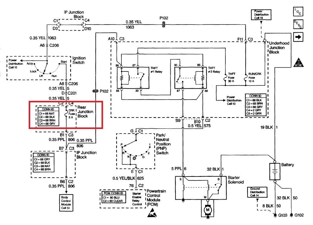
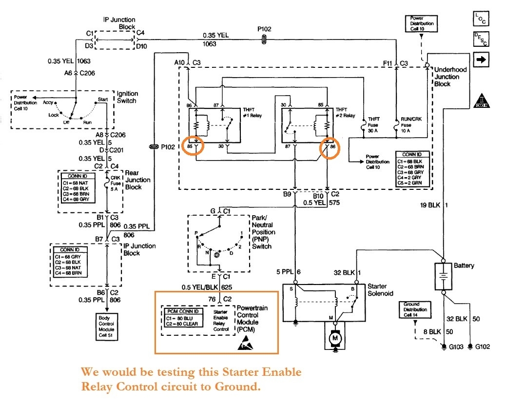
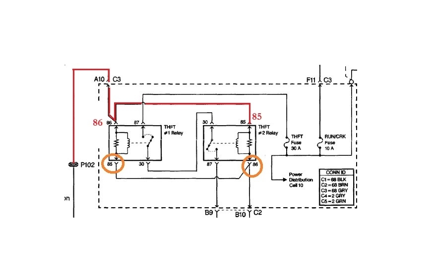
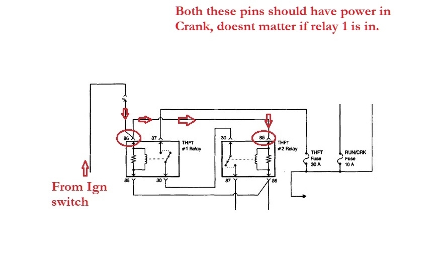
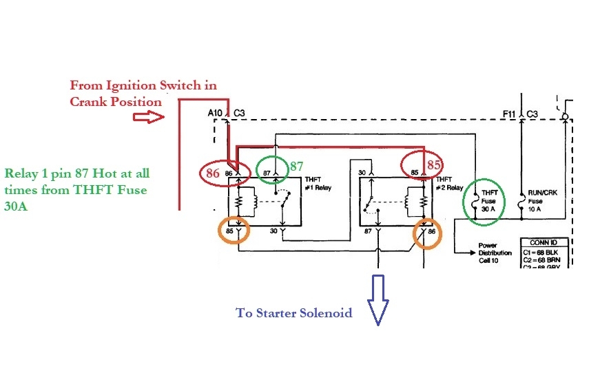
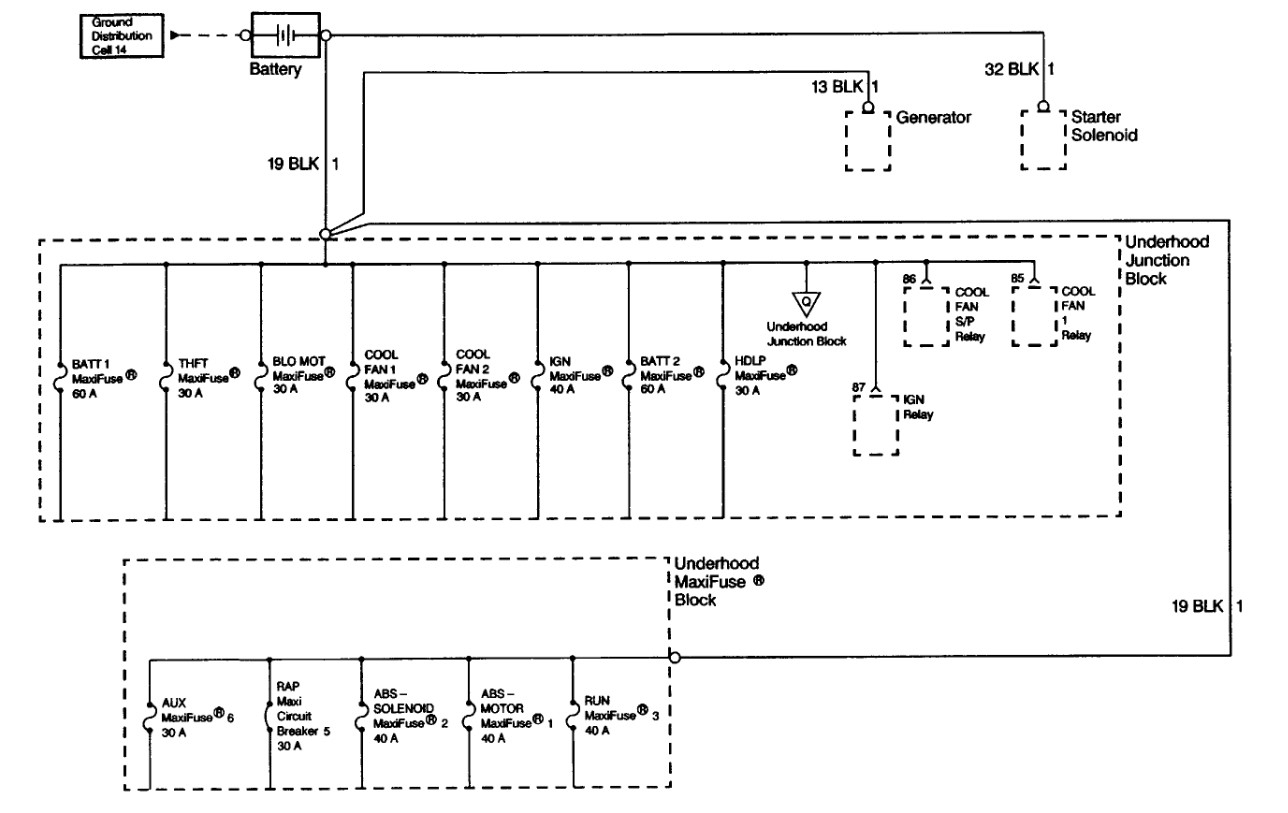
Sorry we must be in different time zones, I would use a multimeter, take out the THFT 1 Relay and first make sure there is power on pin 86 during Crank, which is just above pin 85 on the diagram below, if power is good, then leave your meter on battery Neg, and check pin 85 during Crank, you will be measuring voltage drop to ground threw the PCM which it should read close to 0volts, anything under 500mv (0.5v) roughly is ok.
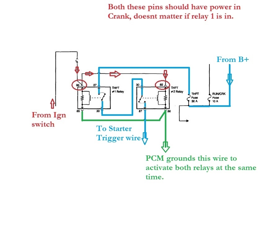
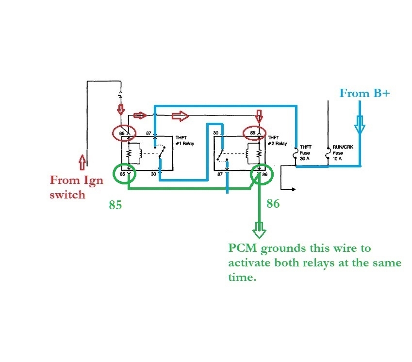
This test is checking there is a good circuit threw the PNP switch, threw the PCM to Ground. Thats how the PCM controls these relays, it grounds both THFT 1 and 2 relays during crank.
Since this was an engine swap, and everything was working electrically before the swap. I think youre going to find this is a wiring issue somewhere, which is common because the harness gets moved around so much during the repair, a connector could have been pulled on, etc. So let me know you have power first then do that test on pin 85.
Most incandescent test lights can pull 250ma, some pull less, I have one that is only a 50ma and a newer one that pulls about 250ma. If these relays are the typical 75 Ohm relays they will pull about 160ma each threw the PCM to ground, and this is where you have to be careful using a test light to check PCM drivers. You dont want to burn out the driver inside the PCM.
You can check how much current your test light draws using your meter in series with the light, if the draw is low enough you could then use it to check for grounding during this test.
On your multimeter you should have 2 other locations to put the red lead in, one should be 10A and the other mA (which is usually up to 200mA), if you want to check the draw on your
test light let me know, Ill give you a diagram to make it easier, or just check for voltage drop as stated above.
Oct 6, 2024 at 12:15 PM