Speedometer not working

2002 MITSUBISHI GALANT
Avatar
WILLV28
  • MEMBER
  • 22 POSTS
Four cylinder front wheel drive automatic 61,409 miles.

Hello,

At first the speedometer and odometer would not work when the radio was on. Now it will not work at all. What might be the cause of this? I check all the fuses, replaced a bad one and it is still happening. But I did get the illumination lights back.

Additional information: It is only the speedometer and odometer. The odometer displays, but does not rack up any new mileage.

Thanks
Dec 9, 2008 at 10:42 AM
Advertisement
Avatar
KHLOW2008
  • CERTIFIED EXPERT
  • 41,814 POSTS
Hi willv28,

When speedometer and odometer fails to work, the most common fault is the speed sensor. I would suggest checking it first. The vehicle speed sensor ( VSS ) is located on top right front of trans-axle housing.

Check out the diagrams (Below). Please let us know if you need anything else to get the problem fixed.
Dec 9, 2008 at 4:09 PM
Avatar
WILLV28
  • MEMBER
  • 22 POSTS
Thank you. I will check it out when I get home from work today. If it pans out, I will donate more, lol. Just a question. I know how to check the voltage to the harness that connects. But how do you know if the sensor itself is bad? PS - I am being thrown no check engine light.
Dec 9, 2008 at 4:25 PM
Advertisement
Avatar
KHLOW2008
  • CERTIFIED EXPERT
  • 41,814 POSTS
Hi willv28, Thank you for the consideration. Mitshubishi is a funny system, quite a number of malfunctions do not show on the CEL but a scanner would retrieve the codes. Vehicle speed sensor (VSS) Remove VSS from rear of transmission or top of trans-axle. Connect 3-10 k/ohm resistor as shown in figure number six . Connect voltmeter between terminals number two and three. Spin shaft of VSS and check for voltage pulsations. There should be about four voltage pulsations per revolution. If there are not four pulsations per revolution, replace VSS.


https://www.2carpros.com/forum/automotive_pictures/192750_VSSTesting02Galant_1.jpg

Dec 10, 2008 at 8:38 AM
Avatar
WILLV28
  • MEMBER
  • 22 POSTS
I am sorry I am being such a pain. But I did not find it. It is just dark when I get home. I did go by this picture as additional help from my manual. I am not hugely mechanically inclined, but, I know I could do this if I could just get to the part.


https://www.2carpros.com/forum/automotive_pictures/103998_29149_mits_g0134_1.gif

Where it is in this picture there is just what looks like a flat plate inserted instead?
Dec 10, 2008 at 4:21 PM
Avatar
KHLOW2008
  • CERTIFIED EXPERT
  • 41,814 POSTS
Hi willv28,

Do not worry about asking many questions. You should be sure of what are required before proceeding with rectification and any questions should be asked to get the correct answer. I would not like you to go into a job without knowing or understanding the situation. That would be bad and instead of rectification, more harm might be derived and time and money would be wasted.

Unplug the wire harness and the part below it is the speed sensor.

Thanks for the picture, it helps. I am going to download it to my PC as I was not able to find a suitable one from my database. ;)
Dec 10, 2008 at 4:42 PM
Avatar
WILLV28
  • MEMBER
  • 22 POSTS
Where that picture shows is nothing, just a black flat plate, no wire harness or anything. I do think I found it though. It was on the part of the transmission directly under the battery. It translates as "supply speed sensor" in google. I do not know why the only references to the part number on the part are in Chinese.
Dec 10, 2008 at 4:58 PM
Avatar
WILLV28
  • MEMBER
  • 22 POSTS
Okay, I was not able to get anything out of the sensor itself. The part does not "spin" as the diagram procedure says. I think they are referring to a different type. The part I find is identical to the one in my manual.

How sure are you it would be this part? Is there anything else in the electrical system, that might cause this? If I knew what the circuit diagram that the sensor was on, that would help me check anything else.

Ugh, what a time for this to happen while I am waiting for a real manual. Haynes manuals are not the best, lol.

Well, I now need to find the part. No one seems to have it the local Mitsubishi dealer wants me to take it in instead.

PS - The part number on the sensor is G4T08371.
Dec 10, 2008 at 5:30 PM
Avatar
KHLOW2008
  • CERTIFIED EXPERT
  • 41,814 POSTS
Hi willv28, The part that you are referring to is the transmission main shaft speed sensor It is not the vehicle speed sensor. From the diagram, look at item three. The VSS is located above the part where Item two (oil seal) is seated. Your picture shows either Item four or five. There are two of them. I am unable to get any parts information from my estimator.


https://www.2carpros.com/forum/automotive_pictures/192750_TranHousing02Galant_1.jpg

Dec 11, 2008 at 6:37 AM
Avatar
WILLV28
  • MEMBER
  • 22 POSTS
Maybe there is something wrong here. Here are some pictures from yesterday and today:


https://www.2carpros.com/forum/automotive_pictures/103998_IMG_0570_1.jpg

This is the view of the car from the driver's side. The part I found was pulled out in this picture. You can somewhat see the spot that was pointed out in that picture of the exact location I posed yesterday.


https://www.2carpros.com/forum/automotive_pictures/103998_IMG_0571_1.jpg

This is the actual part I pulled out. Matched what is in the Haynes manual but does not seem to be it.


https://www.2carpros.com/forum/automotive_pictures/103998_IMG_0572_1.jpg

This is a closeup of that location that is from what is pointed out in the picture from yesterday (which is below). That is what I find when I look there.


https://www.2carpros.com/forum/automotive_pictures/103998_29149_mits_g0134_1.gif

Could it be something is different about this car that what we are looking for? Because those are the only things I can even find. I just looked at all the areas and the last picture of my car comes closest to the location. I guess my confusion is for a reason. lol
Dec 11, 2008 at 2:36 PM
Avatar
KHLOW2008
  • CERTIFIED EXPERT
  • 41,814 POSTS
Hi willv28,

We are in the same boat, both confused. lol.

Well, you are correct, the supposed location of the speed sensor is not being utilized.

I understand some models uses the shaft speed sensors for the speedometer and it is via the PCM. However, those that I found were all about a gear driven speed sensor.

I would try other models to see if I can come up with anything else.
Dec 12, 2008 at 7:30 AM
Avatar
WILLV28
  • MEMBER
  • 22 POSTS
Another person I know told me they do not think it is the speed sensor at all. They think I may have blown the circuity to the speedometer/odometer. But the odometer displays, just does not register new.

He claims that the speed sensor "may be inside the transmission" on this model. Which made me white as a ghost.

When I installed the radio, I did have a wire mixed up with another one. They apparently used the wrong color or one of the colors on the diagram were off. I think that is corrected as the illumination light problem went away when I fixed it and replaced the fuse.

If I cannot get figure it out soon, I will just take it in. I cannot keep driving it not registering miles. Luckily I do not drive much other than to work. Though I cannot really afford much in repairs right now.
Dec 12, 2008 at 3:08 PM
Avatar
KHLOW2008
  • CERTIFIED EXPERT
  • 41,814 POSTS
Hi willv28,

Yes, it is possible the fault does not lie with the speed sensor.

Just to make sure, is there any shifting abnormalities while driving? If no, the speed sensor should be okay. Get a scan done to see if there are any diagnostic error codes. If the speed sensor is faulty, it would show on the scanner.

We shall go with this first. If the results are negative, we shall proceed with testing/checking of the wiring circuit.
Dec 13, 2008 at 8:19 AM
Avatar
WILLV28
  • MEMBER
  • 22 POSTS
Alright, I went to have the codes checked. There were none.

Also, it seems to shift just fine. At least not out of the ordinary.
Dec 13, 2008 at 1:26 PM
Avatar
KHLOW2008
  • CERTIFIED EXPERT
  • 41,814 POSTS
So we can rule out the speed sensor and its circuit to the PCM.

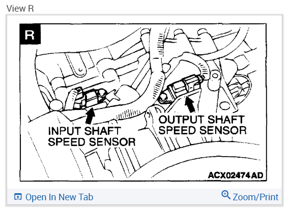
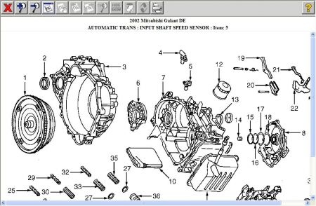
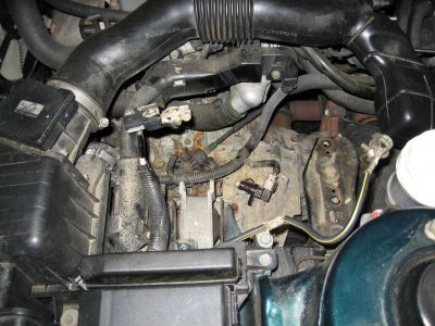
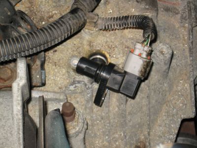
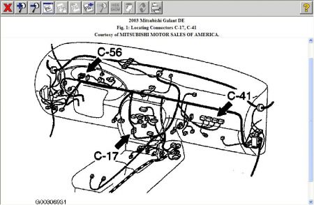
I just checked through another area of my database and it seems the speed sensor is stated as on the side of trans-axle, near firewall, maybe you can check that out to confirm, just out of curiosity and for future reference and some portion of testing requires unplugging the connections.

Anyway, I will provide a complete diagnostic procedures for you to check through and hope an answer is found.

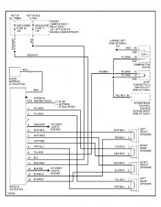
PS. After going through the diagnostic procedure, I believe your radio is the cause of the problem. Refer to # 10

Speedometer does not work:

1. Connect scan tool to data link connector, check for Diagnostic Trouble Code (DTC). If DTC P0500 (Vehicle Speed Sensor) is set, diagnose this DTC first. Go to step 6 . If DTC P0500 is not set, go to next step.

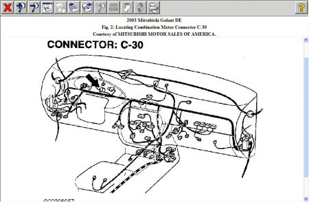
2. On Eclipse, if trip odometer is not working normally, go to next step. If trip odometer is working normally go to step 5. On Galant, if tachometer is not working normally, go to next step. If tachometer is working normally, go to step 5

3. Disconnect instrument cluster connector. Turn ignition switch to ON position. Connect DVOM between ground and instrument cluster connector terminal No. 52 (Black/White wire) on Eclipse or terminal No.29 (Black/White wire) on Galant. If battery voltage is present, go to next step. If battery voltage is not present, check harness connectors and harness wiring between instrument cluster and ignition switch for damage. Repair as necessary.

4. Using a DVOM, check resistance between ground and instrument cluster harness connector terminal No. 34 (Black wire) on Eclipse or terminal No. 30 (Black wire) on Galant. If resistance is less than 2 ohms, replace instrument cluster printed circuit board or speedometer and tachometer. If resistance is greater than 2 ohms, check instrument cluster connector and harness wiring. Repair as necessary. If connector and wiring are okay, go to next step.

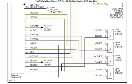
5. Disconnect vehicle speed sensor connector and instrument cluster connector. Turn ignition switch to ON position. Connect DVOM between ground and harness side of instrument cluster connector terminal No. 29 (White/Blue wire) on Eclipse or terminal No. 16 (Yellow/Black wire) on Galant. Voltage should be 5 volts. If voltage is okay, repair or replace instrument cluster printed circuit board or speedometer and tachometer. If voltage is not 5 volts, check instrument cluster connector and harness wiring. Repair as necessary. If connector and wiring are okay, go to next step.

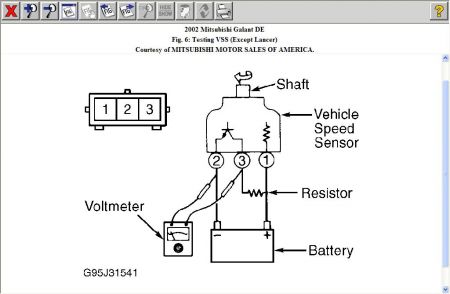
6. Disconnect vehicle speed sensor harness connector and connect DVOM to harness side. Check vehicle speed sensor power supply voltage between terminal No. 1 (Black/White wire) on Eclipse or (Black/Blue wire) on Galant and ground. Battery voltage should be present. If voltage is okay, go to next step. If voltage is not present, check vehicle speed sensor harness connector and wiring. Repair as necessary.

7. Using DVOM, check resistance between ground and vehicle speed sensor harness connector terminal No. 2 (Black wire). Resistance should be less than 2 ohms. If resistance is greater than 2 ohms, check instrument cluster connector and harness wiring. Repair as necessary. If connector and wiring are okay, go to next step.

8. Disconnect vehicle speed sensor harness connector. Connect DVOM between ground and harness side terminal No. 3 (White/Blue wire) on Eclipse or (Yellow/Black wire) on Galant. If 9 volts are not present, check vehicle speed sensor harness connector and wiring. Repair as necessary. If 9 volts are present, go to next step.

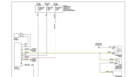
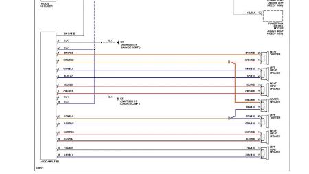
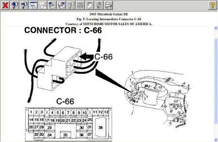
9. Check harness wiring between vehicle speed sensor connector to radio and tape player connector, auto-cruise control ECU ECM (M/T) or PCM (A/T) connector and instrument cluster connector. If connectors or wiring are damaged, repair as necessary. If connectors and wiring are okay, go to next step.

CAUTION: To prevent damage to scan tool, always turn ignition off before connecting or disconnecting scan tool.

NOTE: If ECM (M/T) or PCM (A/T) is replaced, immobilizer-ECU should also be replaced. Each ECM (M/T) or PCM (A/T) has an encrypted code for immobilizer-ECU, and is registered in immobilizer-ECU.

10. Connect scan tool to data link connector. Turn ignition switch to ON position. Read DTC. Disconnect radio and tape player connector. If DTC P0500 does not reset, replace radio and tape player. If speedometer does not work, disconnect auto-cruise control ECU connector. If DTC P0500 does not reset, replace auto-cruise control ECU. If speedometer does not work, disconnect instrument cluster harness connector. If DTC P0500 does not reset, replace instrument cluster. If DTC P0500 resets when any connector is disconnected, replace ECM (M/T) or PCM (A/T).

© 2007 Mitchell Repair Information Co., LLC.
Dec 13, 2008 at 9:59 PM
Avatar
WILLV28
  • MEMBER
  • 22 POSTS
Well, did not need to go beyond step five.

Read the voltage of the wire. It was 5.5 volts. Turned the radio on, it went to 24.89 volts.

So, looks like I found the problem.

So, do you have a wiring diagram for the stereo harness for the 2002 Galant? I will rewire the radio (the harness was cut when I bought it). The diagram I had was not quite right. Make sure the voltage reads right with the radio on/off. Then I will do the repair to the circuit board.

I assume I am replacing the printed circuit board like it says. Whew, $35.00 part if true. Does not look too complicated, lol.

Anything else you want me to do before I order parts, etc? Please advise.
Dec 14, 2008 at 10:15 AM
Avatar
KHLOW2008
  • CERTIFIED EXPERT
  • 41,814 POSTS
Hi willv28, So a simple spark sent us all over the world. If the printed circuit is out, you can have a look at which point it has fused and sometimes a soldering job with a fine wire might save you the $35.00 and the trouble of ordering the parts. I have attached the wiring schematics and the first part one and two are if the vehicle is equipped with amplifier.


https://www.2carpros.com/forum/automotive_pictures/192750_Radio02Galant_1.jpg


https://www.2carpros.com/forum/automotive_pictures/192750_Radio02Galant01_1.jpg


https://www.2carpros.com/forum/automotive_pictures/192750_Radio02Galant02_1.jpg


https://www.2carpros.com/forum/automotive_pictures/192750_Radio02Galant02a_1.jpg

Dec 14, 2008 at 11:24 AM
Avatar
WILLV28
  • MEMBER
  • 22 POSTS
Thank you very much. I think all this information combined solves my problem with the radio.

It appears the wiring diagram I got from someone was way off. But it does many total sense now why the voltage is coming in.

If this changes anything in the diagram, please let me know.

What happened was the diagram they gave me had the yellow-black radio wire going to the antenna power. So, that resulted in me pumping the antenna power into the PCM system when the radio was in tuner mode.

Hopefully I did not damage the PCM in any way.

I will add some funds to this Question.
Dec 14, 2008 at 5:15 PM
Avatar
KHLOW2008
  • CERTIFIED EXPERT
  • 41,814 POSTS
Hi willv28,

Cheers and thank you for the offer.

If you have any other questions, feel free to ask, we will always be there for you.

Merry Christmas!
Dec 15, 2008 at 8:11 AM
Avatar
WILLV28
  • MEMBER
  • 22 POSTS
I got the printer circuit board today. Measured the voltage to the speedometer, it was 5.2 volts with car off and 7.2 with car on. The radio was wired correctly and there was no voltage increase.

After I installed the new circuit board there was no change in the functionality of the speedometer or odometer. Everything else still work perfectly.
Dec 24, 2008 at 2:01 PM
Avatar
KHLOW2008
  • CERTIFIED EXPERT
  • 41,814 POSTS
Hi willv28,

So we meet again. The last time you went up to step five, so maybe you need to continue further down the list to see if you can come up with any new findings.

By the way, did you check if the speed sensor is located at the side of transmission axle near firewall?

It sounds like he blew out the PCM

Merry Christmas!
Dec 24, 2008 at 2:26 PM
Avatar
WILLV28
  • MEMBER
  • 22 POSTS
Yeah, I do not see any other parts on the transmission anywhere near the firewall other than the vacant position we found earlier.

I am getting a new cluster that someone is going to mail to me. I have a feeling that the internals of the speedometer portion of the cluster fried and there is no good way to get inside of it.

Just more time not knowing how fast I'm going or how far I have gone, good thing I am on vacation.

Merry Christmas!

Bill
Dec 24, 2008 at 2:43 PM
Avatar
KHLOW2008
  • CERTIFIED EXPERT
  • 41,814 POSTS
Hi Bill,

Thank you for the additional donations and when you get the new parts, do not forget to let me know the results.

Happy Holidays.
Dec 25, 2008 at 6:01 PM
Avatar
WILLV28
  • MEMBER
  • 22 POSTS
Okay, replace the panel, no change, all instruments work normally except speedometer and odometer. I do not know about number ten in your procedure. There has been no code P0500 given to me at any point during this. The voltages are fine now, so I do not know what else it could be other than the speed sensor, but I do not know where to get to it

Update:

I found this on a forum with someone with a similar issue.

"around 2002, all Mitsubishi's eliminated the dedicated vehicle speed sensor on all the automatics.
why? because all the automatics already had an output speed sensor on them. The vehicle speed sensor was redundant. So now, the output speed sensor on the transmission is used for not only correct shifting, but for vehicle speed. The PCM sends the signal to the gauge cluster. you cannot tap off the output speed sensor, as it is an analog A/C waveform that the PCM interprets. Since you have an older car, I do not think your PCM has the capability of sending the correct signal to the gauge cluster. i think the newer transmissions still had the hole machined in the trans-axle for the vehicle speed sensor, but merely plugged it with a plastic plug. Whether or not the gear is still there is unknown (although you said it is not, so I will take your word on it)."

So, it appears that was likely the correct part I pulled out all that time ago for sending the signal. I will check the voltages to that tomorrow. I had to take off the battery to find it last time. But I can reach the connector by hand still.
Jan 3, 2009 at 5:13 PM
Avatar
WILLV28
  • MEMBER
  • 22 POSTS
Well, I have decided to take it in to my local garage, they are good guys. Hopefully they can help, they said it is possible I would have to go to a dealer. That would stink, because they are forty miles away.

But, I give up. The progress from last time is I measured the voltages from the speed sensor, they are all fine. But the voltage at the speedometer terminal is now four volts even which is not low. I also measured the resistances at the grounds in the instrument panel and the speed sensor. They are both really high. I cannot find a problem with the cabling anywhere.
Jan 7, 2009 at 4:05 PM
Avatar
KHLOW2008
  • CERTIFIED EXPERT
  • 41,814 POSTS
Hi Bill,

Sorry to hear you have not solved the problem. Are you sure the garage is going to be able to assist?

Why do you not go over the trouble shooting steps again and see if you had missed out anything.

I will see if I can get any additional info maybe for 2003 models to see if they fit.

I am not ready to give up. ;)
Jan 8, 2009 at 7:03 AM
Avatar
WILLV28
  • MEMBER
  • 22 POSTS
Thanks for all your help. Sorry this is long.

We have until Tuesday to fix it (I am dropping it off through overnight drop off). I have checked and double checked everything. Ran through the procedure, everything.

The only two small abnormalities are the resistance on the ground is way high, but the tachometer uses the same ground as does everything else and they all still work fine.

But, I thought I was high on voltage on the speedometer wire going to the cluster. It is at 4.00 volts even when key on "on" position. It says it should be fine. Going through both your and the service manual procedure does not yield any results. The voltage on the cluster power is 11.98 voltsand the speed sensor has 11.58 volts.

The garage is a good place, they already told me they were not sure if they could fix that part of it. That it is possible I could need to go to a dealer.

Other things of note the radio does not utilize the speed signal like the manual radio did, so that wire is unused. Also, I think the radio is grounded by a screw directly to the firewall, the radio harness has a ground wire that does not exist, should that be attached somewhere? there is no ground wire in the car radio harness.

Headache, lol
Jan 8, 2009 at 2:55 PM
Avatar
KHLOW2008
  • CERTIFIED EXPERT
  • 41,814 POSTS
Hi Bill, The radio harness does not have any ground wires as it is grounded via casing to body. Since you replaced the radio, if it is a different system from original, you would need to add a ground wire. If the ground resistance is high, it means some place a connection is bad. Tachometer might be working but how accurate is it? Try adding a ground to see if it helps. Following is the test procedure for 03 models but a scan tool is required and I do not know if it is the correct match for your vehicle. TEST PROCEDURE NO. 1: SPEEDOMETER DOES NOT WORK To perform this test, Scan Tool MUT-II (MB991502) and Harness Set (MB991223) must be used. 1. Check the speedometer by observing the other meters. Check to see that the tachometer, fuel gauge and temperature gauge are operating normally. Do all other meters operate?  If YES, go to next step.  CAUTION: To prevent damage to the Scan Tool (MB991502), always turn the ignition switch to LOCK (OFF) position before connecting or disconnecting the scan tool. 2. Using scan tool, check the MFI system for diagnostic trouble codes (DTCs). Connect scan tool to the Data Link Connector (DLC). Turn the ignition switch to the ON position. Check the MFI system for diagnostic trouble codes. Is DTC P0720 set?  If YES, refer to appropriate Multiport Fuel Injection (MFI) DIAGNOSIS article in ENGINE PERFORMANCE. If NO, go to next step. 3. Check combination meter connector C-30 and PCM connector C-41 for damage. Are combination meter connector C-30 and PCM connector C-41 in good condition? If YES, go to next step. If NO, repair or replace the connector. After repair, the speedometer should work normally. 4. Check the wiring harness between combination meter connector C-30 and PCM connector C-41. Also check intermediate connector C-17 and joint connector C-56. See Fig. 1 , Fig. 2 and Fig. 9 . If intermediate connector C-66 or joint connector C-56 are damaged, repair or replace the connector. Is the wiring harness between combination meter connector C-30 and PCM connector C-41 in good condition? If YES, go to next step. If NO, repair the wiring harness. After repair, the speedometer should work normally. NOTE: If ECM (M/T) or PCM (A/T) is replaced, immobilizer-ECU should also be replaced. Each ECM (M/T) or PCM (A/T) has an encrypted code for immobilizer-ECU, and is registered in immobilizer-ECU. 5. Check the speedometer by operating the auto-cruise control system. Does auto-cruise control work normally? If YES, replace the combination meter. After repair, the speedometer should work normally. If NO, replace the PCM. After repair, the speedometer should work normally.


https://www.2carpros.com/forum/automotive_pictures/192750_WireHarn03Galant01_1.jpg


https://www.2carpros.com/forum/automotive_pictures/192750_WireHarn03Galant02_1.jpg


https://www.2carpros.com/forum/automotive_pictures/192750_WireHarn03Galant09_1.jpg

Jan 9, 2009 at 6:58 AM
Avatar
WILLV28
  • MEMBER
  • 22 POSTS
Got nothing out of it. Could be PCM, the cruise will not come on, but I do not think it would anyway. The light used to come on at least even after the issue, now it will not.

I took the car to the garage today. I will be picking it up sometime tomorrow. Let's see if they can figure it out.
Jan 13, 2009 at 8:49 PM
Avatar
KHLOW2008
  • CERTIFIED EXPERT
  • 41,814 POSTS
Hope they can sort it out, if not you are going to have headaches all over, lol.

Good luck.
Jan 14, 2009 at 6:22 AM
Avatar
WILLV28
  • MEMBER
  • 22 POSTS
Well, this has turned into a big debacle. Finally, they replaced the speed sensor and "now the speed is being sent" but it is not being received. So yesterday they drove it to a Mitsubishi dealer. They said the speedometer head was broken and it needed to be sent out to be fixed. So that would leave me without the car until Tuesday.

I reaplced the entire cluster. Is it possible that the issue still existed and the cluster broke again? Might it be fixed if I put in a another cluster?
Feb 5, 2009 at 10:57 AM
Avatar
KHLOW2008
  • CERTIFIED EXPERT
  • 41,814 POSTS
Hi Bill,

Too bad my worse fears are confirmed, you have to start all over again.

It is possible you got a bad cluster or while installing it something gave way. It could be a design flaw where a mistake in installing could break the speedometer head.

If it is the head that is at fault, replacing with a good one should solve the problem. At least we know where we stand now.
Feb 6, 2009 at 9:48 AM
Avatar
RLHANSEN123
  • MEMBER
  • 4 POSTS
how was this resolved? I am having the exact same problem. tachometer works, speedometer does not, odometer does not add miles, but is visible. i have an aftermarket radio that has been installed for a while, though recently i took aftermarket amps out and reconnected original rear speakers about the time my tachometer stopped working.
Sep 16, 2009 at 11:36 PM
Avatar
KHLOW2008
  • CERTIFIED EXPERT
  • 41,814 POSTS
Hi rlhansen123,

You might have the same symptoms but the cause could be something else.

Check/test the vehicle speed sensor first. Get a scan done to see if you can retrieve any trouble codes. Autozone provides free scanning services and let me know the exact code if any found.
Sep 17, 2009 at 8:34 AM
Avatar
RLHANSEN123
  • MEMBER
  • 4 POSTS
when in and made sure there were no lose wires in the radio area. After putting everything back together, everything is working properly.
Sep 19, 2009 at 6:17 PM
Avatar
PHATBOI
  • MEMBER
  • 3 POSTS
Electrical problem
2002 Mitsubishi Galant 4 cyl Front Wheel Drive Automatic

I have read a number of other posts regarding speedometer not working .
What I am wondering is at the radio harness the yellow/black wire what should it show a ground or power ? and if power what voltage ?
This is the wire that is connected to a number of other modules including the cpu. I recieved the car with the wires bare and no radio . I saw the speedo work once
Dec 11, 2018 at 12:50 PM (Merged)
Avatar
JACOBANDNICKOLAS
  • CERTIFIED EXPERT
  • 110,175 POSTS
After looking at the schematic, it runs through the CPU and other modules as you mentioned. When it goes through the CPU, it comes out to ground. Based on that, I would say it shouldn't have any power in it but rather is used as a ground. Here is the schematic. I hope it is big enough for you to see.


https://www.2carpros.com/forum/automotive_pictures/249084_5_47.jpg

Let me know if you have other questions. Also, there are two systems, one with an amp and one without. It does the same on both.
Dec 11, 2018 at 12:50 PM (Merged)
Avatar
PHATBOI
  • MEMBER
  • 3 POSTS
So I tried grounding the wire and no change
My problem is the same as others that I have read, My speedo and odometer dont work.
I put another cluster in it and no change.
I put another transmission in it(mine was slipping)
no change.
I am left with a computer issue?
I hooked my scanner up to it on live feed and drove it and it didnt read a speed either.
What next, there was mention of a wire coming from the cpu to test?
Dec 11, 2018 at 12:50 PM (Merged)
Avatar
JACOBANDNICKOLAS
  • CERTIFIED EXPERT
  • 110,175 POSTS
The only thing I can think of is the vehicle speed sensor. Have you checked that?
Dec 11, 2018 at 12:50 PM (Merged)
Avatar
PHATBOI
  • MEMBER
  • 3 POSTS
there are technically 3 speed sensors
1 input for the cpu
1 output for the cpu
1 for the sppedometer cluster
if one of the cpu sensors were bad wouldnt it throw a code ?
Dec 11, 2018 at 12:50 PM (Merged)
Avatar
2692TROY
  • MEMBER
  • 1 POST
Help ?? I have been working on a 2002 mitsu- galant . I have not been able to figure out why the speedo will not work and also ODO. It will not read how fast the vehicle goes or register the miles. it has 42,671 on the odo but does not read more miles and the speedo doen't work. i have replaced the input speed sensor and the output speed sensor on the transmission . didn't change, replaced the speedo with another one from a salvage yard. didn't work also. mitsubushi dealer ship in town won't give me any help with a wiring schematic , i think it is a wiring problem in the wires to speedo, is it ? if it is can any one help with what wires to test or how to get a wiring diagram
Dec 11, 2018 at 12:50 PM (Merged)