Shut off while driving will not start

1983 JEEP CJ7
120,000 MILES • 4.2L • 6 CYL • 4WD • MANUAL
Avatar
BSUMRELL
  • MEMBER
  • 30 POSTS
Please help! I recently acquired this vehicle and it was running great when I purchased it three weeks ago. Recently replaced the alternator that was not working (confirmed at auto parts store) and the vehicle started up fine with new alternator. On the test drive it shut off about a mile later while driving. Not a sputtering stalling shut off, just quit running. Lights and electrical devices still work. Battery had charge after it shut off and would crank, but not start. Confirmed fuel is getting to the carburetor and flowing when cranking at fuel filter. vehicle will crank fine, just wont fire. Confirmed no spark at plugs with tester. Since it shut off, I have replaced the ICM, starting solenoid and will be replacing the coil today.

Other facts - has nutter bypass installed, TFI ignition upgrade, Weber carburetor.

I am at a loss and running out of ideas. Thoughts?

Thank you!
Apr 24, 2019 at 6:04 AM
Advertisement
Avatar
CJ MEDEVAC
  • CERTIFIED EXPERT
  • 11,004 POSTS
Can you send good clear pics of both sides of the engine?

A good one from overhead with the breather off.

In the mean time.

Coil could be the issue, If you get one, get one that is for an external resistor (picture below)

Let's have a picture of the ignition module too. (Good one, important)

Has your wiring been monkeyed with a lot?

Got voltmeter?

Key on, what value do you have at the positive side of the coil?

Today, I have a two hour mission with my buddy, I'll be back on here until about 11:00 PM Eastern. I'll be on here every day 6:00 until 11:00. We will get you going! CJs need to be alive when needed!

In other words, I'll hang with you!

The Medic
Apr 24, 2019 at 3:41 PM
Avatar
BSUMRELL
  • MEMBER
  • 30 POSTS
Here are some photos. Did a lot of trouble shooting tonight. The coil, ICM and wiring is a little in disarray since I am tracing wires.

Ask away. I may know the answer off the top of my head.

12.5volts on the positive side.

When I crank the engine and use a light probe on negative side of coil I’m not seeing a flashing light. I can only get a light probe to light up when key is in the off position on the negative side. I feel like the ICM isn’t doing it’s job. Remember it has been nuttered.

Monkeyed with - probably. Lots of electrical tape. I’m gradually peeling it back.

Thanks for the help!
Apr 24, 2019 at 7:04 PM
Advertisement
Avatar
BSUMRELL
  • MEMBER
  • 30 POSTS
Photos.
Apr 24, 2019 at 7:09 PM
Avatar
CJ MEDEVAC
  • CERTIFIED EXPERT
  • 11,004 POSTS
Right off the bat.

Bottom of the module shows in your picture.

Lets flip it over and mount it to the fender (wherever) The body needs a good ground! Let's make it look like this (wherever you mount it) See last picture.

Give me another closer picture when it's done, I want to see the wires to it really good.

You have two connectors to the module, how many wires go from each connector to the module itself? (should be 2 from one and 4 from the other)

My second diagram shows a 1979, this is how things were prior to the computer in later years.

"Nutter bypassing" is nothing more than bypassing the computer crap and imitating a 1979's (1980, 1981) wiring to the distributor and coil. In other words, Yours should look like my diagram now!

Return with better news!

The Medic

Apr 24, 2019 at 9:07 PM
Avatar
BSUMRELL
  • MEMBER
  • 30 POSTS
Photos for reference.
Apr 25, 2019 at 6:09 AM
Avatar
BSUMRELL
  • MEMBER
  • 30 POSTS
Medic – thanks for getting back to me and hanging in there!

Sorry for the photos being low quality, it was dark last night when I took them. I am usually working on it at night

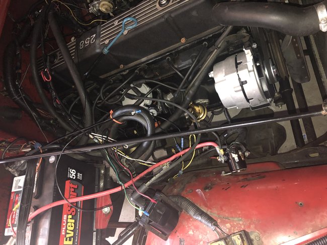
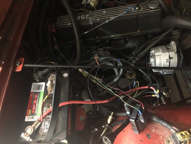
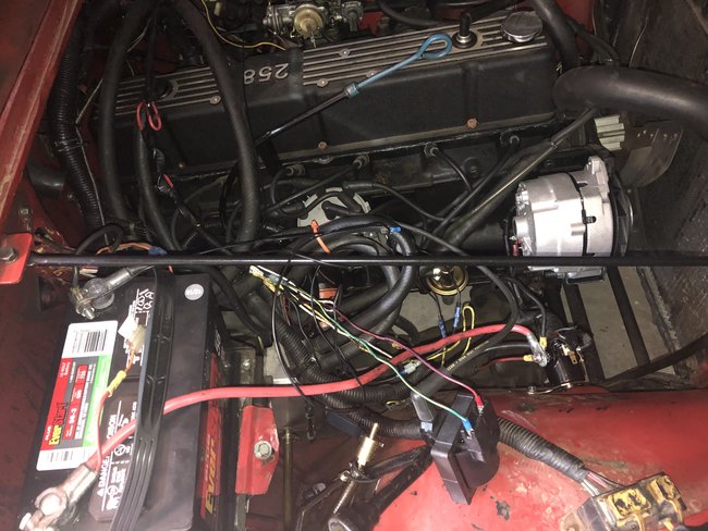
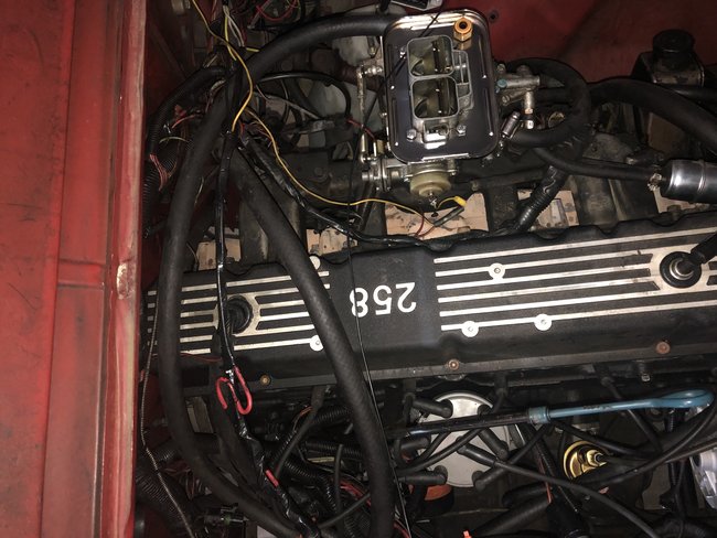
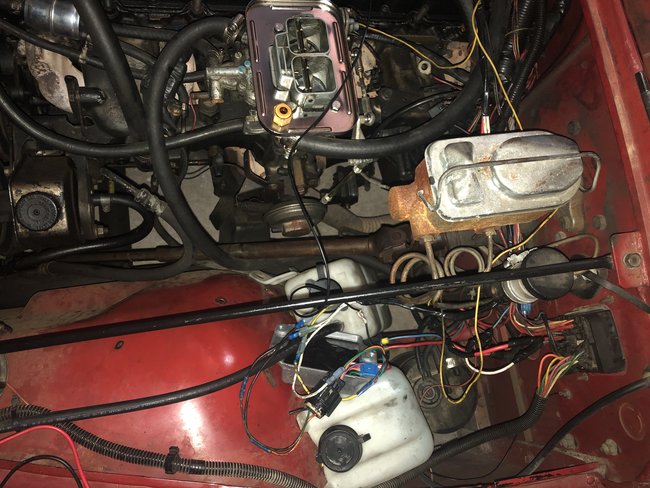
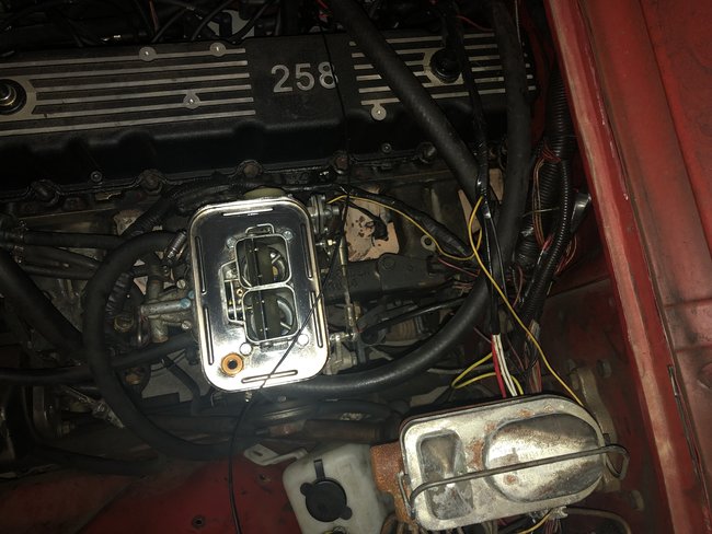
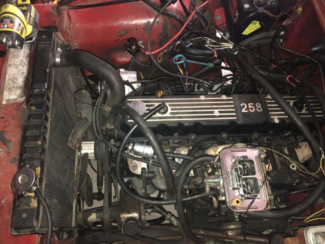
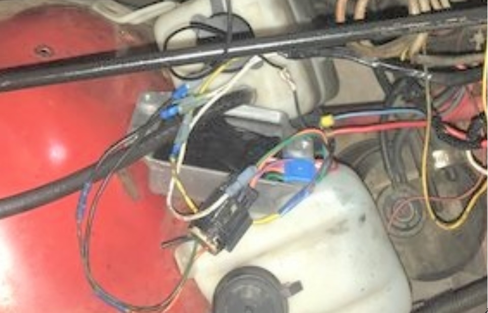
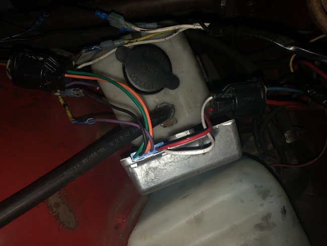
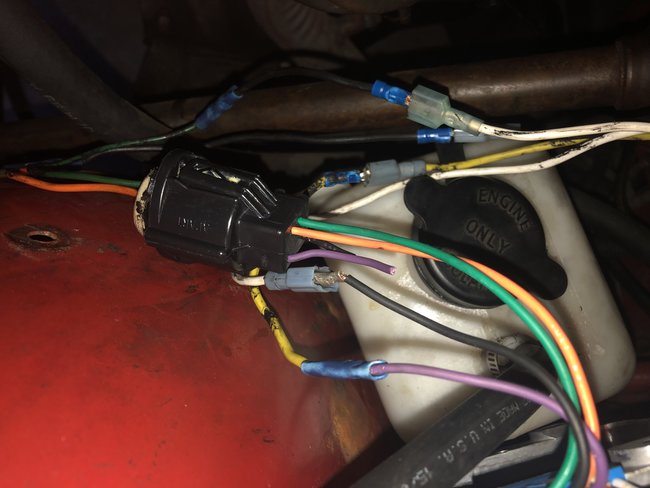
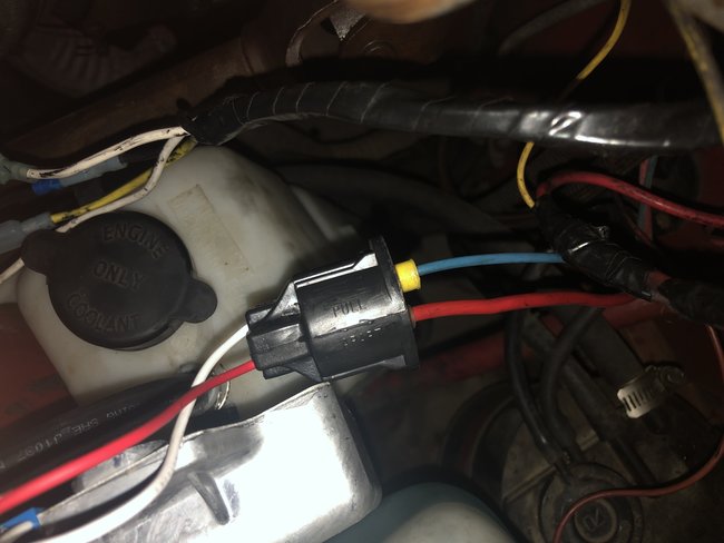
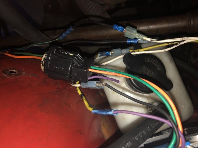
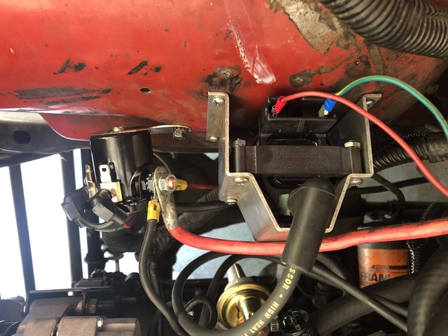
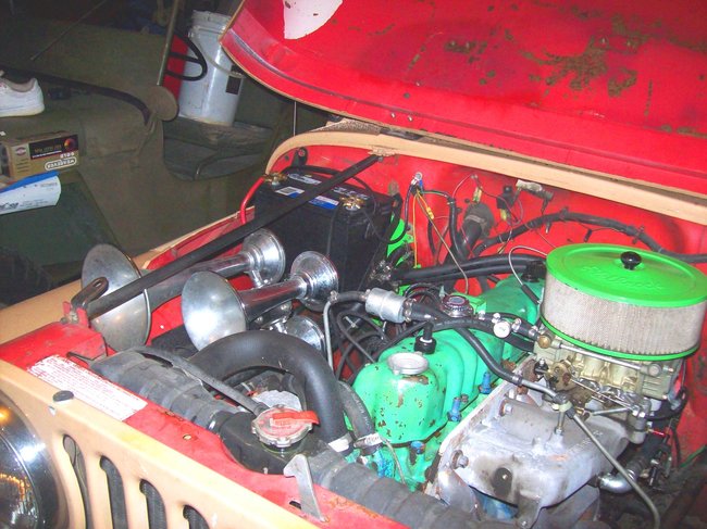
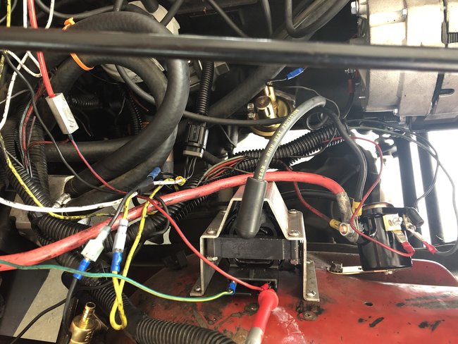
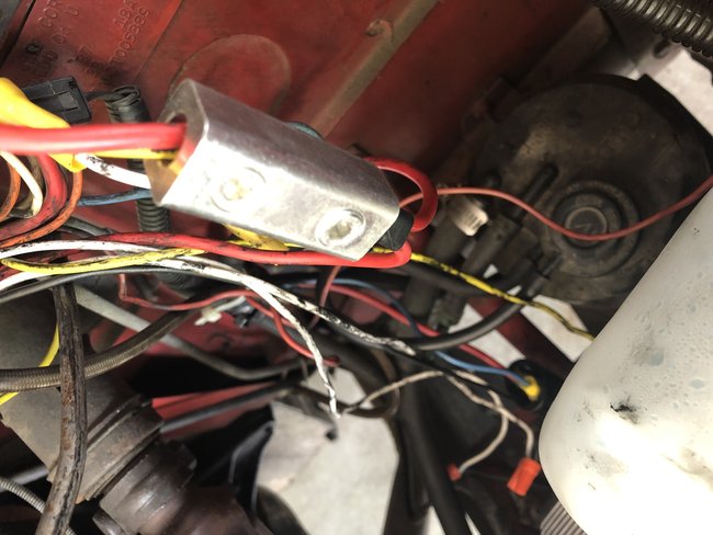
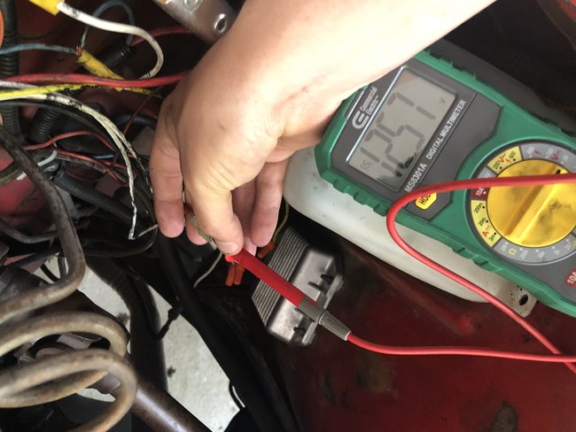
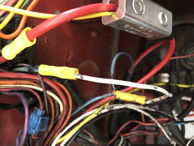
Photos attached from this morning showing the connections to the ICM. I have a red and blue going into the module; a green and orange leaving the module (through the factory module female connector) and purple and black leaving the module (through a splice to other wires). When I replaced the module I put everything back in the same configuration as I found them originally. I will re-mount the module to the fender wall (where I found it) tonight – had it out to help with diagnosis access. I am a little concerned about all of the splices, though they were there when I got it.

A couple of other points ("light" refers to probe test light lighting up)
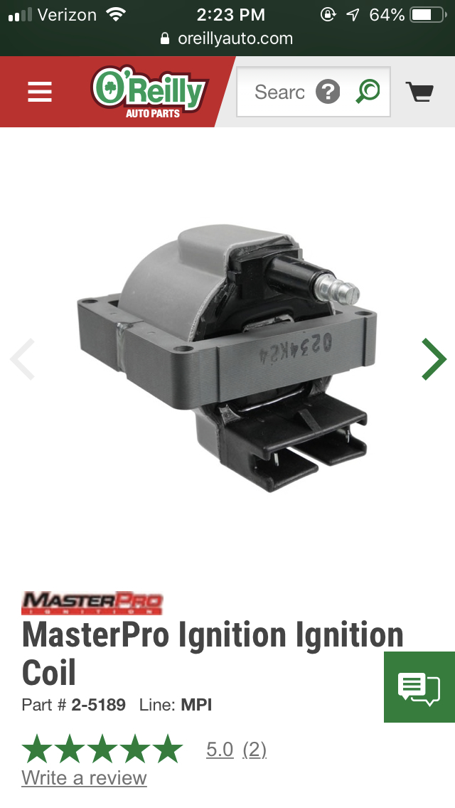
Coil:
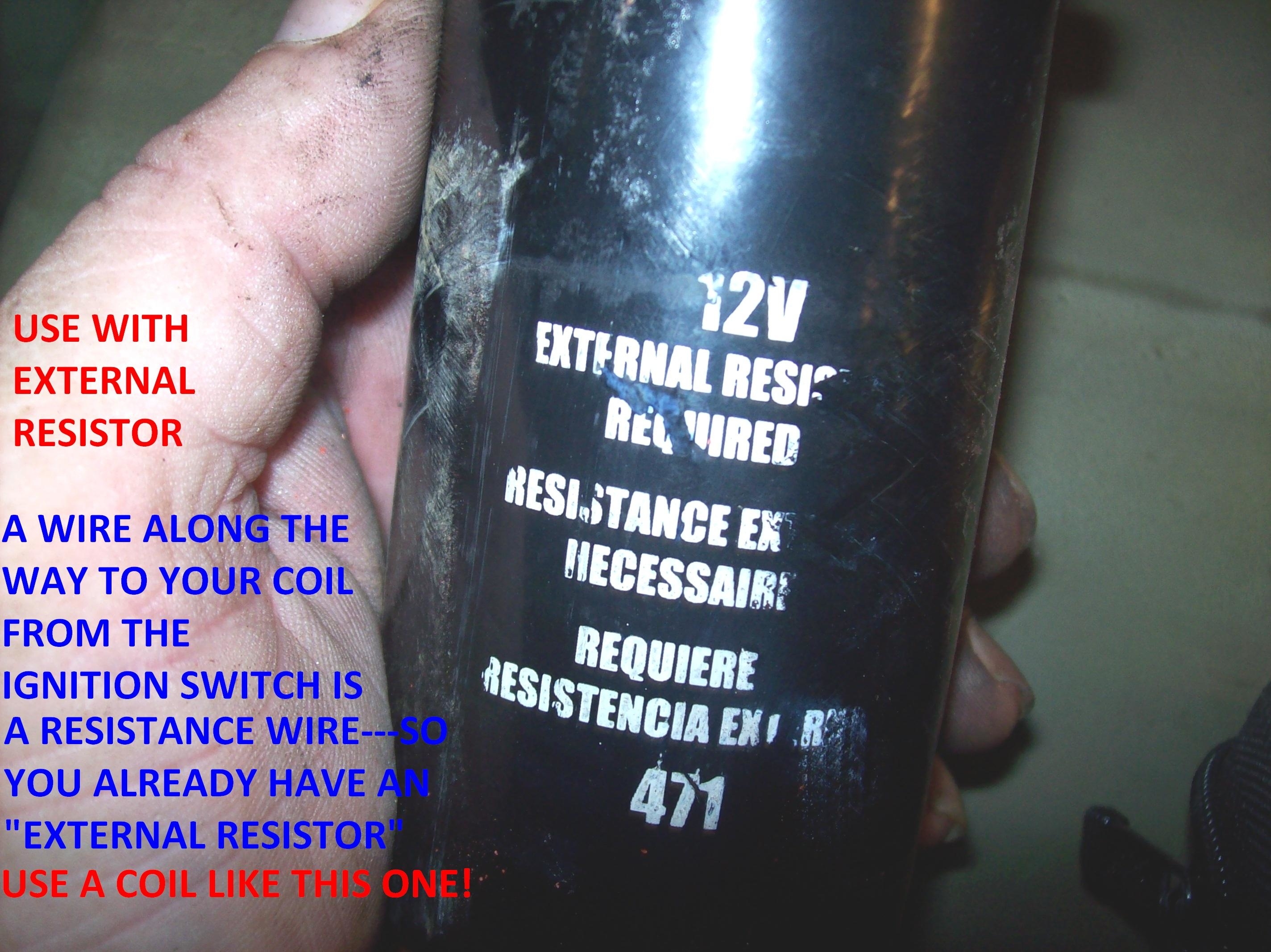
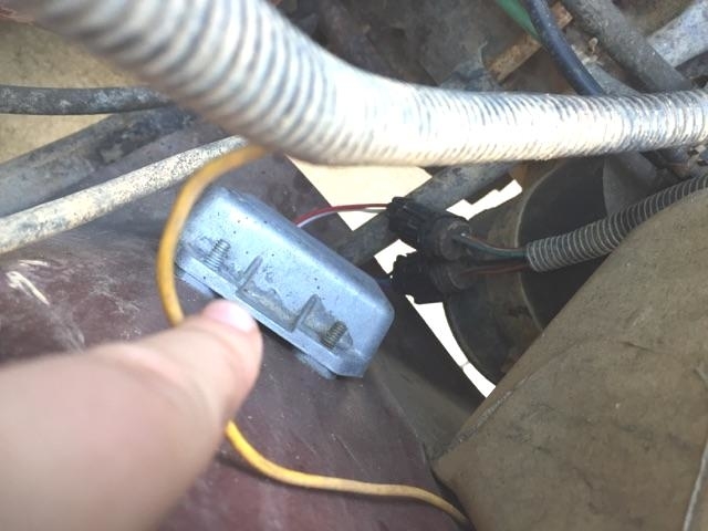
- It has a "TFI upgrade" per PO which uses a coil from a 90’ Ford. The coil has a bracket that will mount it to the fender that I will re-install.
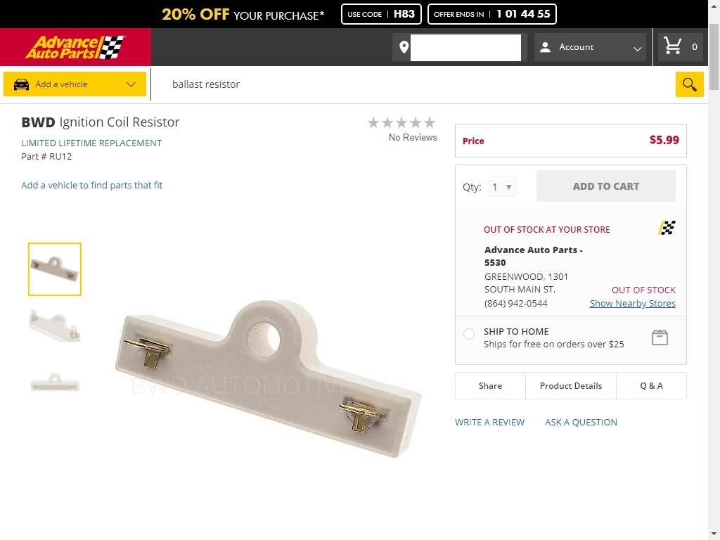
- I was getting zero resistance from positive to negative on the old coil (after I had replaced the alternator) so I replaced the coil.
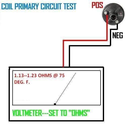
- New coil - I get a +/- 0.5 ohm reading from positive to negative.
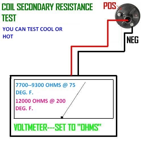
- New coil – I get a +/- 7500 ohm reading from positive or negative to distributor lead.
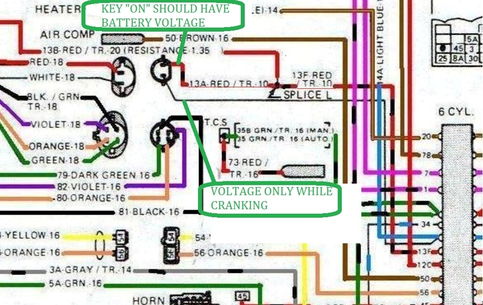
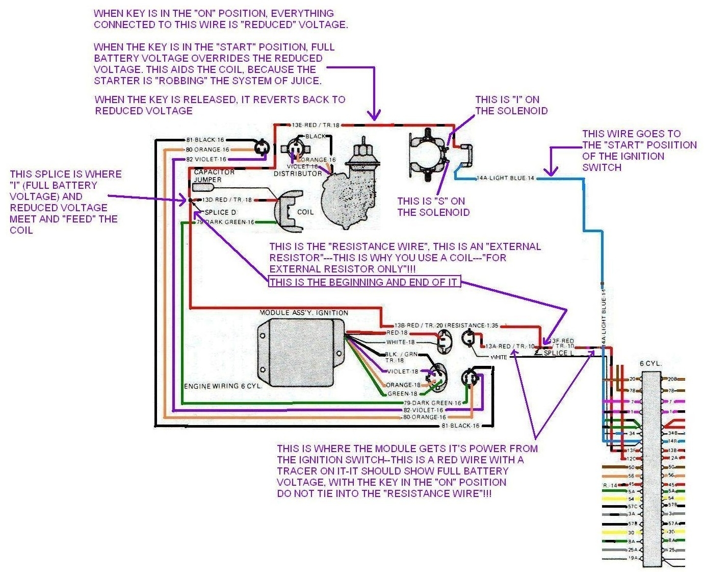
- Got a "light" when I probe the positive (Red) wire connector at the coil when the key is in “on” position.
- Got a "light" when I probe the positive wire connector at the coil when I crank the engine.
- NO "light" when I probe the negative (Green) wire connector at the coil when the key is in “on” position.
- Got a "light" when I probe the negative (Green) wire connector at the coil when the key is in “off” position.
- NO "flashing light" when I probe the negative (Green) wire connector at the coil when I crank the engine.

Module:
- Replaced the module (after I replaced the alternator) as I was told that could go with the alternator by the P.O.
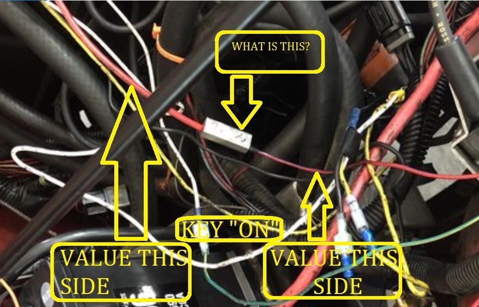
- I get a "light" when I probe the blue wire going to module (harness side) when I crank the engine. (2-wire connector)
- I get a "light" when I probe the larger red wire going to the module (harness side) when key is in "on" position. (2-wire connector)
- I get a "light" when I probe the black wire (Ground) at the connector (harness side) to the module (4-wire connector)
- I made a jumper wire from the battery negative to the coil negative (Green) and got a "light" when I tested the green wire at the connector (harness side) to the module (4-wire connector)
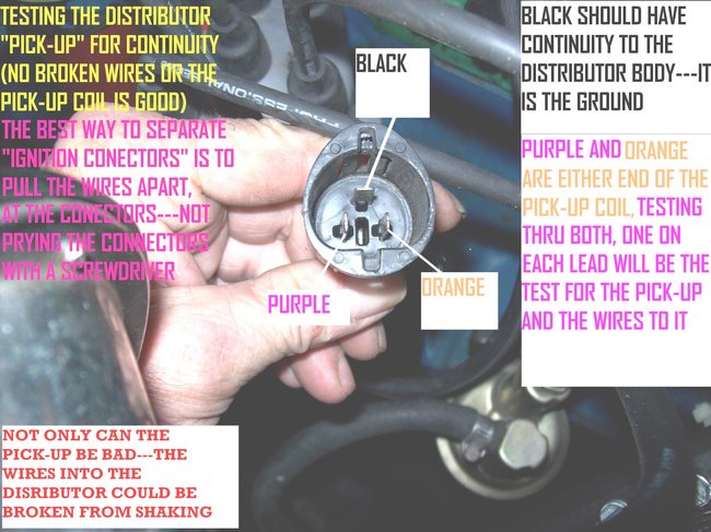
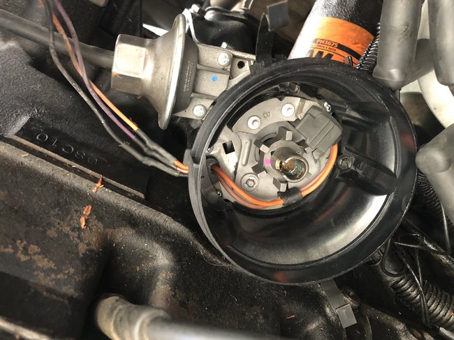
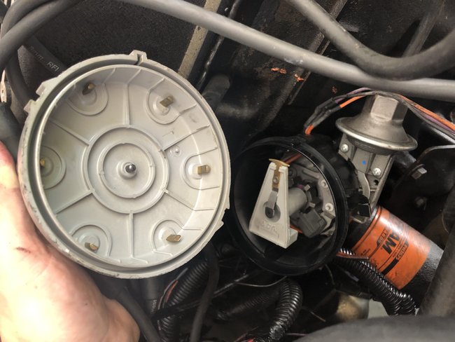
Distributor:
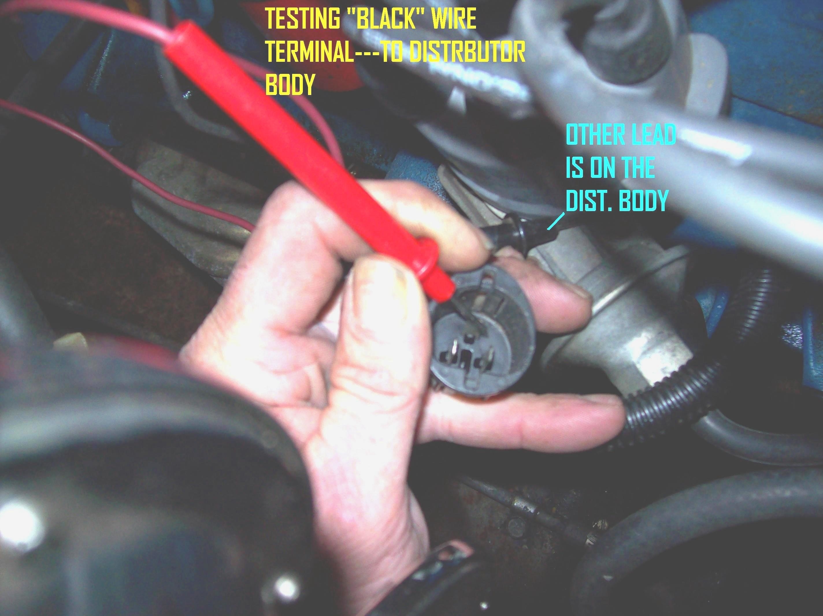
- I get a "light" when I probe the black wire at the connector attached to the distributor. Seems to confirm the distributer is grounded.
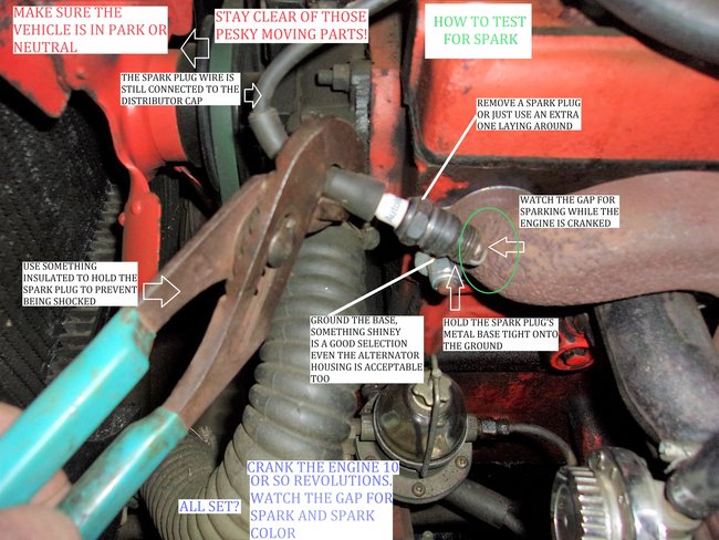
- I put a spark plug test light in one plug wire and get no light when cranking.

Starting Solenoid:
- Replaced it (after I replaced the alternator).

Other thoughts:
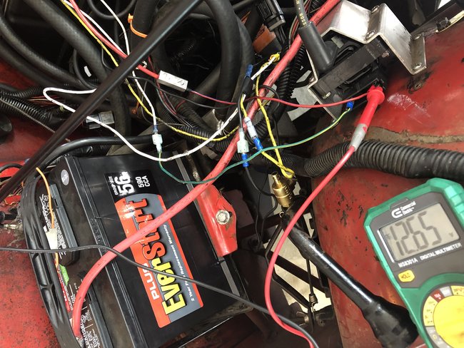
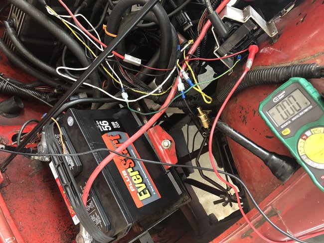
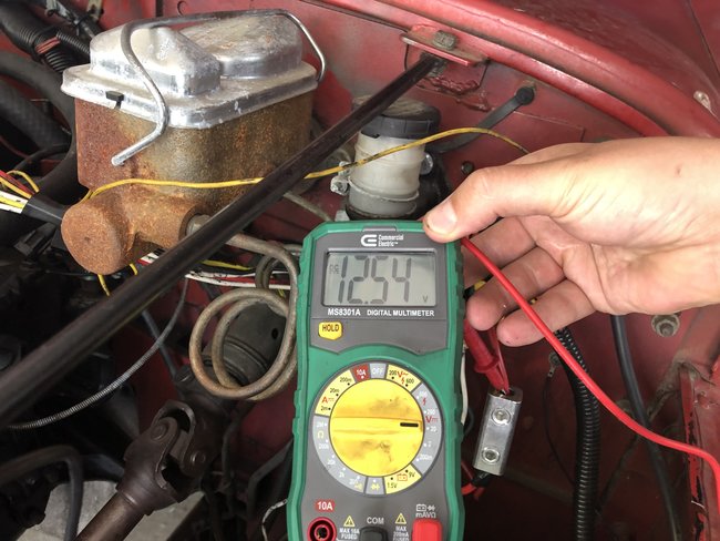
- Battery holds charge at +/- 12.6 V
- When the alternator died, could that have "taken" anything else with it?
- Could I have caused another issue when installing the new alternator?
- Could having the module not mounted to the fender cause the problem?
- Could having the coil not mounted to the fender cause the problem?
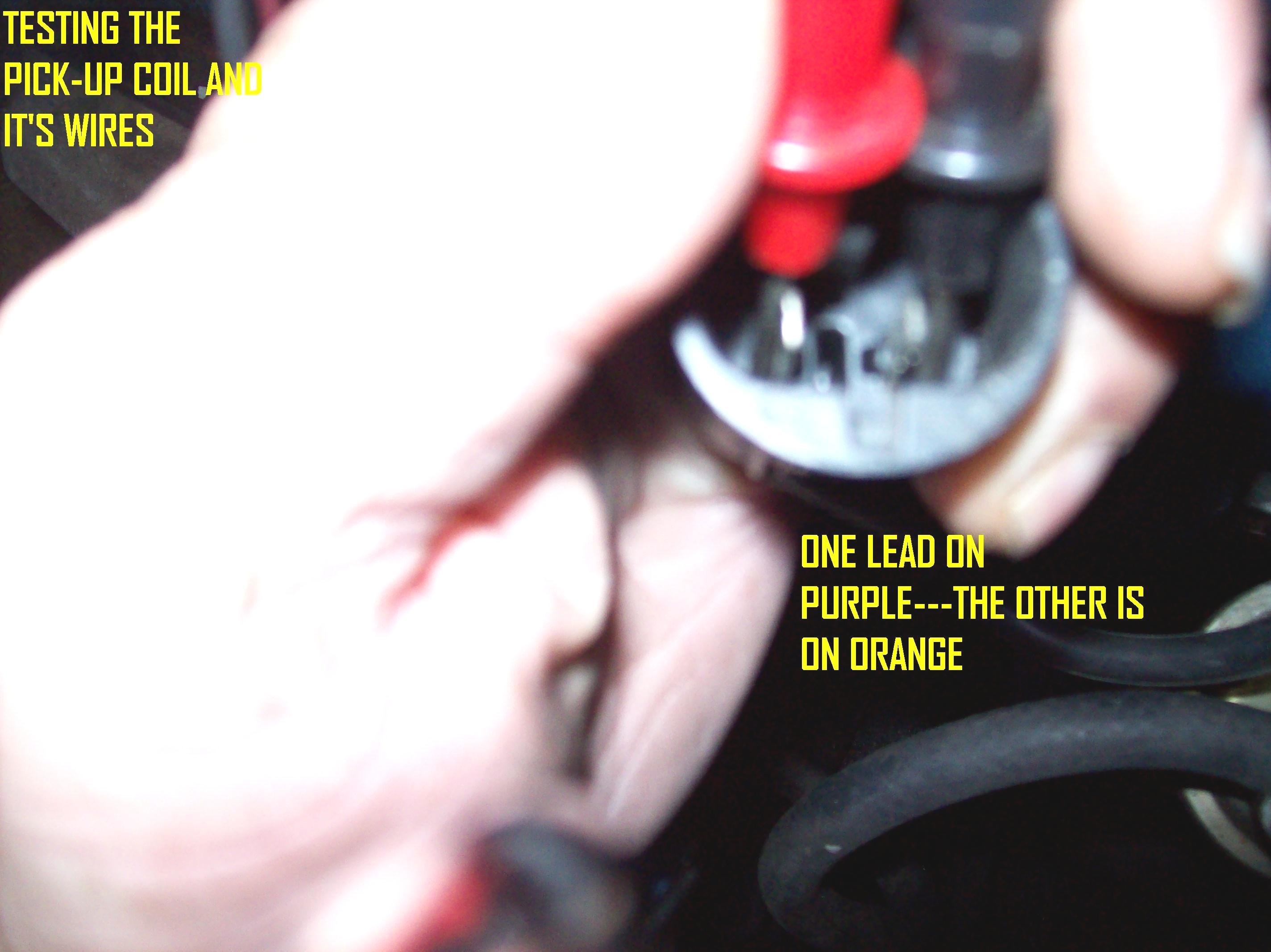
- I am not sure I have confirmed the orange and purple wires from the module to the distributor are not broken.

Hope all of this is clear (as mud) enough to make sense on your end. Let me know what thoughts you have!!

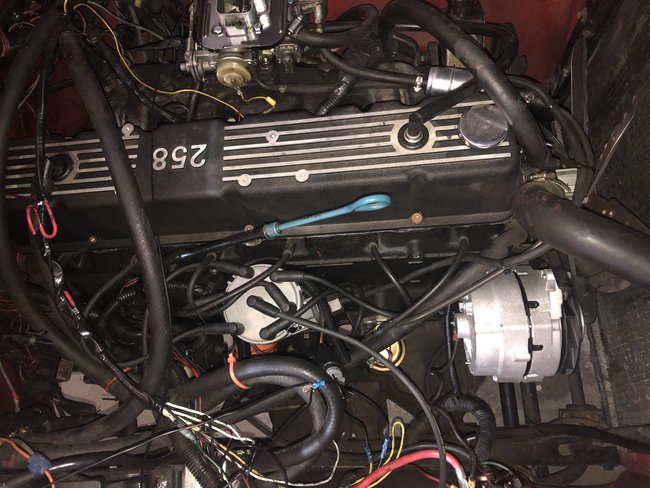
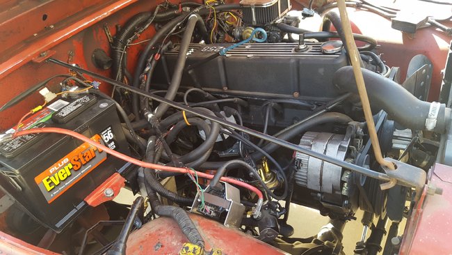
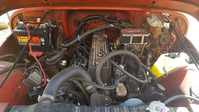
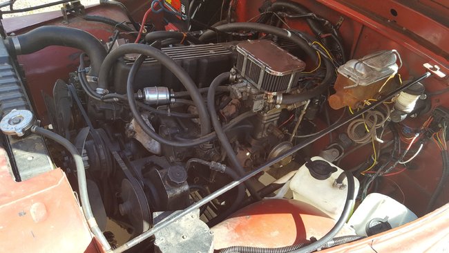
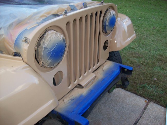
Photos above - 3 from this morning of the module and connections, 3 from when I bought it showing the original state of everything - pre alternator and ignition issue.
Apr 25, 2019 at 6:11 AM
Avatar
CJ MEDEVAC
  • CERTIFIED EXPERT
  • 11,004 POSTS
Do you have a cheap digital voltmeter?

"Harbor Freight" has them for $5.00, what a deal!

I have more tests for you using one.

The Medic
Apr 25, 2019 at 7:05 PM
Avatar
BSUMRELL
  • MEMBER
  • 30 POSTS
Yes I do. You list the tests and I’ll report back with numbers and my findings. Thanks!
Apr 25, 2019 at 7:11 PM
Avatar
CJ MEDEVAC
  • CERTIFIED EXPERT
  • 11,004 POSTS
You are so on top of it!

We are going to use pictures!

I also want you to trace the colors of the ignition module to their final destinations. Verify they go exactly where the ones in my diagram go to (posting the diagram from before, again).

I want the voltage reading from the positive side of the coil with the key "on".

Sometimes your buddies mess with you, make sure you have a rotor button and it is not damaged. Make sure it turns when the engine is cranking over.

The Medic

Apr 25, 2019 at 8:25 PM
Avatar
BSUMRELL
  • MEMBER
  • 30 POSTS
Was hoping to find something obviously wrong but didn’t! Uggh.

Battery voltage = 12.58
Voltage at coil positive with key “on” = 12.36

Showing 0.2 ohm when testing distributor ground black wire per your photo.

Showing 619k ohm when testing orange and purple at distributor per your photo.

Traced orange, purple, black, green from coil and distributor and they land where they should per your photo. I also checked continuity from end to end and got 0.1 ohm from end to end.

That would be a bad joke! See photos of distributor. Confirmed it is turning when spinning. Checked for spark with tester and didn’t get one.

Re mounted the coil and ICM.

Thoughts? Thanks for the help.
Apr 26, 2019 at 1:21 PM
Avatar
CJ MEDEVAC
  • CERTIFIED EXPERT
  • 11,004 POSTS
You can stick a needle or pin in the wire (insure it contacts the copper).

Or

Separate the connector.

Or

Find your own way to check these.

Findings?

Diagram below

The Medic
Apr 26, 2019 at 6:41 PM
Avatar
BSUMRELL
  • MEMBER
  • 30 POSTS
Alright! Battery has been on a charger so it’s a bit higher than normal. Just now the battery voltage is 13.11 and the red wire is 12.91 with key on. Other wire has no voltage with key on and 11 volts when cranking.
Apr 26, 2019 at 7:12 PM
Avatar
CJ MEDEVAC
  • CERTIFIED EXPERT
  • 11,004 POSTS
Has the distributor been out or picked up since it last ran?

Pop the distributor cap again. This time, see if you can turn the rotor button forcibly with your fingers. Not enough force to break the rotor. Just enough to insure the gear's pin at the bottom of the shaft did not shear, and now the shaft and gear are not in sync as the gear is maybe slipping (just a check!).

Verify your spark tester works on another vehicle or test for spark the traditional way. Picture below.

The Medic
Apr 26, 2019 at 7:41 PM
Avatar
BSUMRELL
  • MEMBER
  • 30 POSTS
No I haven’t picked up the distributor since it last ran, just opened the lid a couple times. I have tried to turn the rotor by hand and cannot without too much force. I’ll check for spark the old fashioned way tomorrow and report back. One note, when I purchased the module I didn’t ask them to check it. Think it could be defective? Also should I get any specific readings on the green wire leaving the coil when I am cranking the engine?
Apr 26, 2019 at 7:48 PM
Avatar
BSUMRELL
  • MEMBER
  • 30 POSTS
Update: I removed some old splices and connectors at the ICM and reconnected it. Was able to get a spark on a test plug per your photo. Replaced the plug wire and she fired up. Kept foot on gas for a bit and let her run for one minute, sounded normal. Tried to slow to idle and she stalled out. Went back an hour or so later and she started up again and sounded normal. Then stalled when I pulled the headlight plug to see if they worked when engine was running, stalled out. Now I cannot get a spark again. Back to where I was.

Now, with key on, reading battery voltage at the red ICM wire, at the + and - coil wire and red wire at starting solenoid. With key off I’m seeing battery voltage at - green wire at coil. Getting 0.5 ohm resistance on coil + to - and 845 k Ohms from + to distributor wire.

I’m using a MasterCraft ICM.

Help! I am out of ideas. What am I missing? Everything seems to be reading per your pictures and diagrams.

Thanks. Frustrated in Texas!
Apr 27, 2019 at 12:03 PM
Avatar
CJ MEDEVAC
  • CERTIFIED EXPERT
  • 11,004 POSTS
Does the positive side of the coil have voltage with the key "off"?

If so, does it (the positive wire) have voltage disconnected from the coil?

Same goes for the negative coil wire.

Key "off", any voltage to the negative wire (it can stay attached) (with the positive wire still disconnected)

Are there other wires connected to the negative coil (or wire) or anywhere along it's path to the ignition module?

Let's go back to the two wire connector.

One had battery voltage with the key "on".

The other had power when cranking - did this one have any power while it was "not" cranking?

Is there one of these connected in your system, it would be in the wire on the way to the positive side of the coil. See picture.

Frustrated! Look at me, I can't walk up and move wires about and say, "Maybe this is it!". Pretty much I'm always stuck trying to talk a 747 passenger on how to land with low fuel!

Chin up! We'll get it!

The Medic
Apr 27, 2019 at 5:24 PM
Avatar
BSUMRELL
  • MEMBER
  • 30 POSTS
I just needed a pep talk! Thanks for hanging in there and getting back to me. I bet it’s hard to text out solutions to problems sight unseen. Really want to figure this out!

Key off - no power on positive at coil, but I do have battery voltage power at the negative side (one tester lead on positive battery terminal, one on green negative connector).

Connector to module 2-wire side - power at red only when key on. both have power when cranking. No power to blue (white in your photo) when key is on.

No ballast resistor to be found. Been looking for one but haven’t found it. Should there be one?

Keep the ideas coming!
Apr 27, 2019 at 9:11 PM
Avatar
CJ MEDEVAC
  • CERTIFIED EXPERT
  • 11,004 POSTS
"Key off - no power on positive at coil, but I do have battery voltage power at the negative side (one tester lead on positive battery terminal, one on green negative connector)."

On positive battery terminal? Other on green negative connector? Looks like this would provide voltage not check for it?

Let's try this instead of that!

Voltmeter negative lead on battery negative terminal and stays there! Voltmeter positive lead touches the negative terminal of the coil. Key "off" (results?) Now try the same with the key "on" (results?)

Your year should have a "resistance wire" to the coil, unless someone gutted it out. If so, you will need a ballast resistor. Let me know (or will help you find out for sure). I will explain the deal better when you return.

The Medic


Apr 27, 2019 at 9:36 PM
Avatar
BSUMRELL
  • MEMBER
  • 30 POSTS
Volt meter negative lead on battery negative. Key off. Positive lead on negative connector at coil. No read. Key on. Reads 12.67 volts. Battery voltage is 12.76 volts.

I have a jumper wire from what I can tell that follows the path of your photo. It splices in at the red wire through the firewall by driver, runs over top of engine to near the coil, splits and feeds both the coil and the starting solenoid.

No ballast resister. Should I have one cut in the jumper wire?

Alternator has a two prong connector with one wire leaving it that is brown. There is no ground wire hooked to the alternator.
Apr 28, 2019 at 7:53 AM
Avatar
CJ MEDEVAC
  • CERTIFIED EXPERT
  • 11,004 POSTS
I know this is boring and repetitive.

Just want to make sure of the values.

Voltmeter black lead to the negative battery terminal,
red voltmeter lead to the positive coil terminal. Value key "on"? Value key "off"?

The jumper mentioned above comes from the starter solenoid and "tees" into the positive wire on the coil.

Is this correct?

Is "I" in my diagram what this jumper you mentioned is doing/ going to?

The Medic
Apr 28, 2019 at 9:16 AM
Avatar
BSUMRELL
  • MEMBER
  • 30 POSTS
Photos attached.

Photo 1 - key on. Reading of 12.65.

Photo 2 - key off. No reading.

Photo 3 - splice at jumper. Left small wire goes to starting solenoid. Right small wire goes to coil.

Photos 4 - splice at firewall by driver. Top red wire is power in. Bottom left leaving red wire is jumper. Bottom right leaving red wire is to ICM.

Photo 5 - key on. reading at splice to jumper and ICM. Drops to zero with power off.

Photo 6 - key on - reading at red ICM wire. Zero with power off.

Photo 7 - two splices. Bottom splice - blue wire from the right is from the ICM. Splices to white wire. White wire splices to two blue wires coming through fire wall.

Apr 28, 2019 at 10:27 AM
Avatar
CJ MEDEVAC
  • CERTIFIED EXPERT
  • 11,004 POSTS
No pictures?

The Medic
Apr 28, 2019 at 11:12 AM
Avatar
BSUMRELL
  • MEMBER
  • 30 POSTS
They are there now.
Apr 28, 2019 at 11:18 AM
Avatar
CJ MEDEVAC
  • CERTIFIED EXPERT
  • 11,004 POSTS
As you can see, 'splaining wires positions is a hard task to do.

I may have you draw a diagram or I will make you a drawing and you connect the "dots" with wires and where they go.

I'll jump on that soon!

I came across this. (picture 1)

The Medic

Apr 28, 2019 at 11:46 AM
Avatar
CJ MEDEVAC
  • CERTIFIED EXPERT
  • 11,004 POSTS
OK- Magic with the pics? 1st there were none. Then there was 1, now a whole bunch!

Go to your Jeep, touch the "Jeep" emblem at the door way and say "Abracadabra you are now healed". Let me know how that works out!

The Medic
Apr 28, 2019 at 11:50 AM
Avatar
BSUMRELL
  • MEMBER
  • 30 POSTS
Magic spell didn’t work! But I’ll
Keep trying.

Yeah it is tough to explain. Wish you could see it with your own eyes! That aluminum thing is a splice. Value is roughly the same on each side of it. This splice is where the two small wires leave (to the right of your photo), one heads to solenoid, other heads to coil.

What are some other values I should be looking for?

So strange - started yesterday briefly now won’t budge.
Apr 28, 2019 at 11:51 AM
Avatar
CJ MEDEVAC
  • CERTIFIED EXPERT
  • 11,004 POSTS
I see what the mysterious block is now with the magical pictures, I thought it was a resistor. It is merely a mechanical butt splice. They need to be taped up (re-taped up) to prevent them from touching something and shorting or grounding out.

The Medic

Apr 28, 2019 at 11:57 AM
Avatar
CJ MEDEVAC
  • CERTIFIED EXPERT
  • 11,004 POSTS
Can you send me a link or part number for your coil and where it came from?

I may be on to something. If the original wiring had been kept and the add-on goodies had just been popped into place this could of maybe been easier to follow!

It's a challenge, but you are definitely a big help in explaining it!

Thank goodness you are the only CJ in my garage right now, seems I won't see one for 4 months, then 4 of them will hit me at once!

The Medic
Apr 28, 2019 at 12:16 PM
Avatar
BSUMRELL
  • MEMBER
  • 30 POSTS
Okay, I’ll tape them up going forward. Thanks for the help today.
Apr 28, 2019 at 12:21 PM
Avatar
BSUMRELL
  • MEMBER
  • 30 POSTS
This is a photo of it. The previous owner said he did a TFI upgrade. It is a mid 90’s Ford coil.

Another note. I put in a new ICM yesterday when it started running. Not sure if that had anything to do with it.
Apr 28, 2019 at 12:24 PM
Avatar
CJ MEDEVAC
  • CERTIFIED EXPERT
  • 11,004 POSTS
I take it that it will not run now with the new module?

If no runnage, think you could warranty that one back?

If so, do not hook the next one in until I show you the next plan.

The Medic
Apr 28, 2019 at 12:30 PM
Avatar
BSUMRELL
  • MEMBER
  • 30 POSTS
Yeah no runnie with the new one in. I had to chop off the connector to splice it I so I doubt I can take it back. But I might try ;).

I will hold for further instructions.
Apr 28, 2019 at 12:31 PM
Avatar
CJ MEDEVAC
  • CERTIFIED EXPERT
  • 11,004 POSTS
Get one of these.

https://www.oreillyauto.com/detail/b/standard-ignition-5753/lighting---electrical-16777/ballast-resistor-12489/50f244faac31/standard-ignition-2-terminal-ballast-resistor/ru37/5817019?q=ballast+resistor&pos=11

Notice on the backside view that the cavity is sealed that contains the spring-like resistor coil, I have found these kinds last longer, I don't know if it's because the coil doesn't get dirty or the springy part does not bounce around.

We want this puppy to run well.

I'm sure it did so prior to someone "thinking" it could run like a dragster or a F-16 by listening to other folks about some funky modifications.

The distributor modification did what? I have never seen the stock distributor cap cross fire being used on the street.

The plugs fire just fine with a normal stock distributor, coil, and stock plugs.

So,

Let's get one of these too!

https://www.oreillyauto.com/detail/b/masterpro-ignition-4513/ignition---tune-up-16776/ignition-coils-19690/ignition-coil-12493/90c5da72ae86/masterpro-ignition-ignition-coil/25190/4598800/1979/jeep/cj7?q=coil&pos=4

Again, Let's wait until we get everything and I show you how to configure this stuff. Maybe as a "test" at 1st, then permanently after it's proven. I suspect the module can't handle what's going on now.

Wanna make a good modification/ improvement?

Jetting/ tweaking the carburetor is the best improvement possible!

I can guide you with this too. After we get this running again.

The Medic

Apr 28, 2019 at 12:59 PM
Avatar
BSUMRELL
  • MEMBER
  • 30 POSTS
Sounds like a plan.

Three questions:

Will this work? I already have it from trying to replace the coil earlier this week.

https://www.oreillyauto.com/detail/b/super-stock-2719/ignition---tune-up-16776/ignition-coils-19690/ignition-coil-12493/90c5da72ae86/accel-super-stock-ignition-coil/8140/2473952/1983/jeep/cj7?q=Ignition+Coil&pos=3

Second, think the ICM is shot? Should I get a new one just in case? Which one from Oreilly would be best suited?

Third, will my distributer work ok with this coil?
Apr 28, 2019 at 3:31 PM
Avatar
CJ MEDEVAC
  • CERTIFIED EXPERT
  • 11,004 POSTS
I done a bunch of researching of that coil.

It will work with a 1.8 OHM ballast resistor.

Seems few places that have ballast resistors do not boast on what the resistance rating is.

I finally found this one:

https://www.autozone.com/ignition/ballast-resistor/duralast-ballast-resistor/116673_0_0

You can also take your voltmeter with you and maybe find one with right 1.8 resistance.

Many times the online (and local parts) stores want you to give the application. This would maybe work if the wiring was not changed.

Yours is now in the twilight zone, everything for your ignition is special and not OE. It's best to get a zip-lock bag and tear the labels from the boxes and stick them in the bag. In the future you will be able to produce a part number for what you need.

Example of mine

I have a '77 CJ-5, originally it had a "Prestolite Ignition System". The '77 did not have a resistance wire, and had many quirks and problems with the Prestolite.

I opted to change the ignition to be "Motorcraft" exactly like '79, '80, '81.

I needed resistance (I did not install a resistance wire) I used a ballast resistor, I got a reman distributor for $50, a coil for a '79, new plug wires, and several working ignition modules from an auto salvage yard (maybe $10 for 3) and I poured through the Ford vehicles until I found the correct connectors for the module and distributor. The wires on them were various lengths and had to be spliced to be correct for my application (those wires and connectors were freebies!)

Now if I need something from a parts store for the ignition I tell them I have a '79 w/ a 258 (not a '77) The only thing that is not '79 and is kind of "oddball" is the ballast resistor.

Let me know when you are ready to proceed.

The Medic


Apr 28, 2019 at 4:57 PM
Avatar
BSUMRELL
  • MEMBER
  • 30 POSTS
Okay, I’ll get that resistor, 1.8 ohm. And plan to use the coil I already have.

Will my current distributor be right for the application?

I’ll be ready to work on this tomorrow night so you can lay the procedure out when you are ready.
Apr 28, 2019 at 5:09 PM
Avatar
CJ MEDEVAC
  • CERTIFIED EXPERT
  • 11,004 POSTS
Distributor should be fine.

See you tomorrow!

The Medic
Apr 28, 2019 at 5:13 PM
Avatar
BSUMRELL
  • MEMBER
  • 30 POSTS
Got the parts and standing by.
Apr 29, 2019 at 3:21 PM
Avatar
BSUMRELL
  • MEMBER
  • 30 POSTS
***Additional Info - when I got the engine to run over the weekend, I pulled the plug to test the headlights and the engine stalled out. Thoughts?
Apr 30, 2019 at 5:56 AM
Avatar
CJ MEDEVAC
  • CERTIFIED EXPERT
  • 11,004 POSTS
What plug was pulled?

Bear with me, I'm on the ole trusty laptop for a while.

The Medic
Apr 30, 2019 at 3:19 PM