Aug 21, 2020 at 2:50 PM
(Merged)
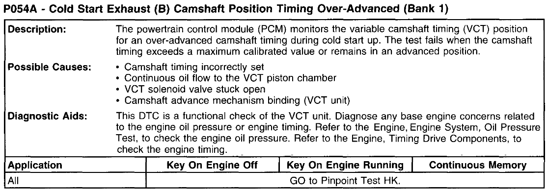
Camshaft Position Sensor Location and Replacement ?
2019 FORD F-150
Advertisement
Thanks. so the shaft of the sensor doesn't go into a hole? I can see the bolt hole and prob line it up but was unsure about a hole for the shaft.
Well, I believe that I got pretty lucky overall. I'm assuming it was a mouse but it chewed on the pigtail of my wiring harness for my vacuum pump. It's going to be around $430.00 to get it fixed. Is what it is I guess.
Thanks for all the help.
Thanks for all the help.
Aug 21, 2020 at 2:50 PM
(Merged)
Advertisement
Okay, thanks. just to be clear the shaft of the sensor doesn't have to fit into a hole?
Aug 21, 2020 at 2:50 PM
(Merged)

That is likely the problem. Let me know if it takes care of the issues. Darn mice! You have no idea how many times they have caused problems.
Take care,
Joe
Take care,
Joe
Aug 21, 2020 at 2:50 PM
(Merged)
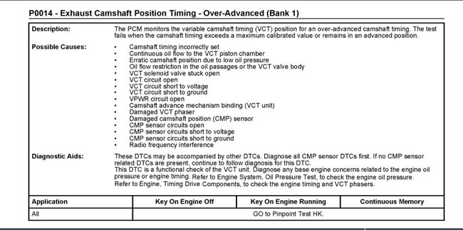
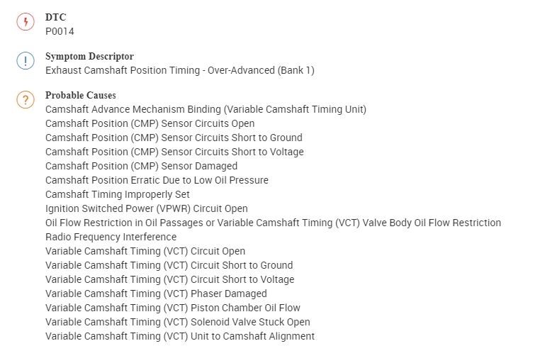
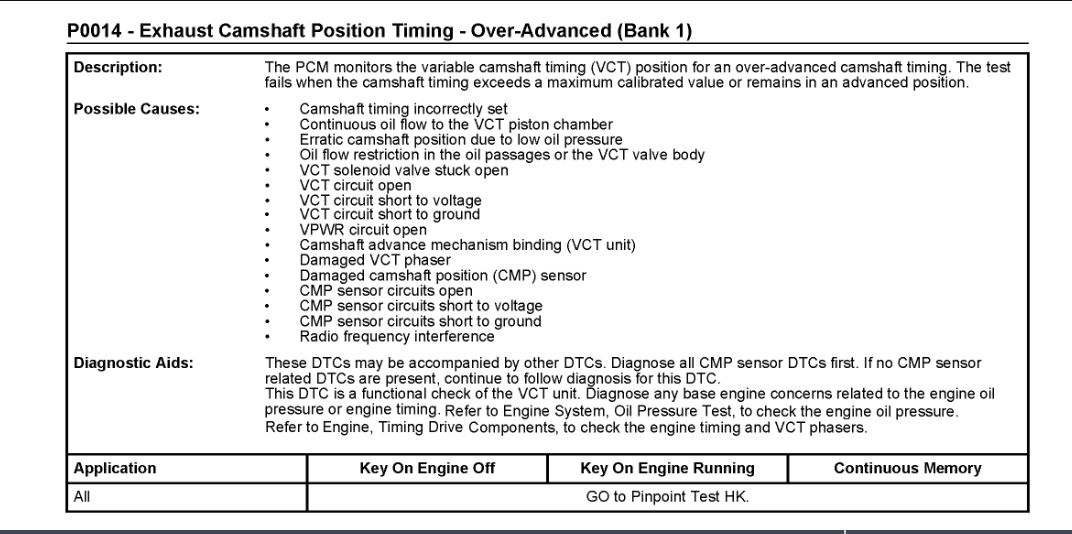
Truck stalled then wouldn't start ran odm on it came up with code P0014.
Aug 21, 2020 at 2:50 PM
(Merged)

Good morning,
This is a complicated code as there are so many possibilities.
It could be anything from a bad timing chain to a bad guide or phaser, a clogged oil control valve from sludge in the oil to a electrical issue.
https://www.2carpros.com/articles/how-camshaft-variable-valve-timing-works
The diagnostic tree is below and you will need an advanced scan tool to monitor the system.
https://www.2carpros.com/articles/how-to-check-wiring
https://www.2carpros.com/articles/how-to-use-a-voltmeter
HK: Variable Camshaft Timing (VCT)
HK: Introduction See: Computers and Control Systems > Diagnostic Trouble Code Tests and Associated Procedures > HK: Variable Camshaft Timing (VCT) - Introduction
HK1 CHECK FOR DIAGNOSTIC TROUBLE CODES (DTCS)
Note:These DTCs may be accompanied by other DTCs. Diagnose all CMP sensor DTCs first. If no CMP sensor related DTCs are present, continue to follow diagnosis for the DTC. If any CMP DTCs are present, GO to Pinpoint Test DR See: Computers and Control Systems > Diagnostic Trouble Code Tests and Associated Procedures > DR: Camshaft Position (CMP) Sensor - Introduction. If no CMP DTCs are present, continue to follow this test.
Are DTCs P000A, P000B, P0010, P0011, P0012, P0013, P0014, P0015, P0016, P0017, P0018, P0019, P0020, P0021, P0022, P0023, P0024, P0025, P052A, P052B, P052C, P052D, P054A, P054B, P054C, P054D, P2088, P2089, P2090 or P2091 present?
Yes
For DTC P0010, P0013, P0020, P0023, P2088, P2089, P2090 and P2091, GO to HK2.
For all others, GO to HK10.
No
For symptoms without DTCs, GO to HK10.
For all others, GO to Section 4, Diagnostic Trouble Code (DTC) Charts and Descriptions See: Computers and Control Systems > Diagnostic Trouble Code Tests and Associated Procedures > Diagnostic Trouble Code (DTC) Charts and Descriptions.
HK2 DTCS P0010, P0013, P0020, P0023, P2088, P2089, P2090 AND P2091: CHECK FOR VCT DTCS
Note:The engine should be at operating temperature before running the self-test.
Clear the PCM DTCs.
Carry out the PCM self-test.
Are DTCs P0010, P0013, P0020, P0023, P2088, P2089, P2090 or P2091 present?
Yes
GO to HK4.
No
GO to HK3.
HK3 CARRY OUT A THOROUGH WIGGLE TEST ON THE VCT HARNESS
Carry out a thorough wiggle test on the VCT harness.
Carry out the PCM self-test.
Are DTCs P0010, P0013, P0020, P0023, P2088, P2089, P2090 or P2091 present?
Yes
GO to HK4.
No
GO to Pinpoint Test Z See: Computers and Control Systems > Diagnostic Trouble Code Tests and Associated Procedures > Z: Intermittent - Introduction.
HK4 CHECK THE VCT SOLENOID RESISTANCE
Note:Diagnose the suspect VCT solenoid indicated by the DTC.
Ignition OFF.
Disconnect the VCT solenoid related to the current DTC.
Measure the resistance between:
image
Is the resistance between 5 - 14 ohms?
Yes
GO to HK5.
No
INSTALL a new VCT solenoid. REFER to Computers and Control Systems Electronic Engine Controls.
Clear the PCM DTCs. REPEAT the self-test.
HK5 CHECK THE VCT SOLENOID FOR INTERNAL SHORTS
Measure the resistance between:
image
Is the resistance greater than 10K ohms?
Yes
GO to HK6.
No
INSTALL a new VCT solenoid. REFER to Computers and Control Systems Electronic Engine Controls.
Clear the PCM DTCs. REPEAT the self-test.
HK6 CHECK THE VPWR CIRCUIT FOR AN OPEN
Ignition ON, engine OFF.
Measure the voltage between:
image
Is the voltage greater than 10.5 V?
Yes
GO to HK7.
No
REPAIR the open circuit. Clear the PCM DTCs. REPEAT the self-test.
HK7 CHECK THE VCT CIRCUIT FOR AN OPEN
Ignition OFF.
PCM connector disconnected.
Measure the resistance between:
image
Is the resistance less than 5 ohms?
Yes
GO to HK8.
No
REPAIR the open circuit. Clear the PCM DTCs. REPEAT the self-test.
HK8 CHECK THE VCT CIRCUIT FOR A SHORT TO GROUND
Measure the resistance between:
image
Is the resistance greater than 10K ohms?
Yes
GO to HK9.
No
REPAIR the short circuit. Clear the PCM DTCs. REPEAT the self-test.
HK9 CHECK THE VCT CIRCUIT FOR A SHORT TO VOLTAGE
Ignition OFF.
Ignition ON, engine OFF.
Measure the voltage between:
image
Is any voltage present?
Yes
REPAIR the short circuit. Clear the PCM DTCs. REPEAT the self-test.
No
GO to HK14.
HK10 CONTINUOUS DTCS P000A, P000B, P0011, P0012, P0014, P0015, P0016, P0017, P0018, P0019, P0021, P0022, P0024, P0025, P052A, P052B, P052C, P052D, P054A, P054B, P054C AND P054D: CHECK THE OPERATION OF THE VCT SYSTEM
Note:Some vehicles require higher RPMs and loads to actuate the VCT system than others. The VCTADVERR PID, VCT_INT_DIF PID or VCT_EXH_DIF PID should be close to zero whether actuating or not. During rapid VCT movements, the VCTADVERR PID, VCT_INT_DIF PID or VCT_EXH_DIF PID may momentarily deviate from zero.
Note:For a symptom based concern, monitor all applicable PIDs during this step.
Clear the PCM DTCs.
For Escape 2.5L, Expedition, F-150, F-Series Super Duty, Fusion 2.5L, Navigator:
For DTCs P0011, P0012, P0016, P052A and P052B,
Access the PCM and monitor the VCTADV (ANGL) and VCTADVERR (ANGL) PIDs.
For DTCs P0018, P0021, P0022, P052C and P052D,
Access the PCM and monitor the VCTADV2 (ANGL) and VCTADVERR2 (ANGL) PIDs.
For all others:
For DTCs P000A, P0011, P0012, P0016, P052A and P052B,
Access the PCM and monitor the VCT_INT_ACT1 (ANGL) and VCT_INT_DIF1 (ANGL) PIDs.
For DTCs P000B, P0014, P0015, P0017, P054A and P054B,
Access the PCM and monitor the VCT_EXH_ACT1 (ANGL) and VCT_EXH_DIF1 (ANGL) PIDs.
For DTCs P0018, P0021, P0022, P052C and P052D,
Access the PCM and monitor the VCT_INT_ACT2 (ANGL) and VCT_INT_DIF2 (ANGL) PIDs.
For DTCs P0019, P0024, P0025, P054C and P054D,
Access the PCM and monitor the VCT_EXH_ACT2 (ANGL) and VCT_EXH_DIF2 (ANGL) PIDs.
Drive the vehicle while exercising the throttle to generate VCT movement.
Does the VCTADV PID, VCT_INT_ACT PID or VCT_EXH_ACT PID indicate VCT movement while the VCTADVERR PID or VCT_INT_DIF PID or VCT_EXH_DIF PID maintain close to zero?
Yes
Unable to duplicate or identify the concern at this time. The concern
may have been caused by an oil flow restriction which was removed by
opening the VCT solenoid.
No
If the engine runs rough at idle and KOER or continuous memory DTCs are present, GO to HK12.
For all others, GO to HK11.
HK11 CHECK THE FUNCTIONALITY OF THE VCT SYSTEM
Note:Diagnose the suspect VCT solenoid indicated by the DTC.
Ignition OFF.
Disconnect the VCT solenoid related to the current DTC.
Ignition ON, engine running.
Connect a 5 amp fused jumper wire between the following:
image
Connect a 5 amp fused jumper wire between the following:
image
Does the engine reduce speed, run rough or stall with the jumper connected?
Yes
The concern is not present at this time.
The concern may have been caused by an oil flow restriction which was removed by opening the VCT solenoid.
Clear the PCM DTCs. REPEAT the self-test.
No
GO to HK12.
HK12 CHECK THE FUNCTIONALITY OF THE VCT SOLENOID
Ignition OFF.
Disconnect the VCT solenoid related to the current DTC.
Connect a 5 amp fused jumper wire between the following:
image
Connect a 5 amp fused jumper wire between the following:
image
Listen for an audible click in the VCT solenoid.
Repeat as necessary to verify the VCT solenoid click.
Does the VCT solenoid click?
Yes
GO to HK13.
No
INSTALL a new VCT solenoid. REFER to Computers and Control Systems Electronic Engine Controls.
Clear the PCM DTCs. REPEAT the self-test.
HK13 CHECK THE BASE ENGINE OIL PRESSURE
Check the base engine oil pressure. Refer to Engine, Engine System, Oil Pressure Test.
Are any concerns present?
Yes
REPAIR as necessary.
Clear the PCM DTCs. REPEAT the self-test.
No
INSTALL a new VCT phaser as necessary.
Clear the PCM DTCs. REPEAT the self-test.
HK14 CHECK FOR CORRECT PCM OPERATION
Disconnect all the PCM connectors.
Visually inspect for:
pushed out pins
corrosion
Connect all the PCM connectors and make sure they seat correctly.
Carry out the PCM self-test.
Verify the concern is still present.
Is the concern still present?
Yes
INSTALL a new PCM. REFER to Section 2, Flash Electrically Erasable Programmable Read Only Memory (EEPROM) See: Computers and Control Systems > Diagnostic Trouble Code Tests and Associated Procedures > Flash Electrically Erasable Programmable Read Only Memory (EEPROM), Programming the VID Block for a Replacement PCM.
No
The system is operating correctly at this time. The concern may have been caused by a loose or corroded connector.
Images (Click to enlarge)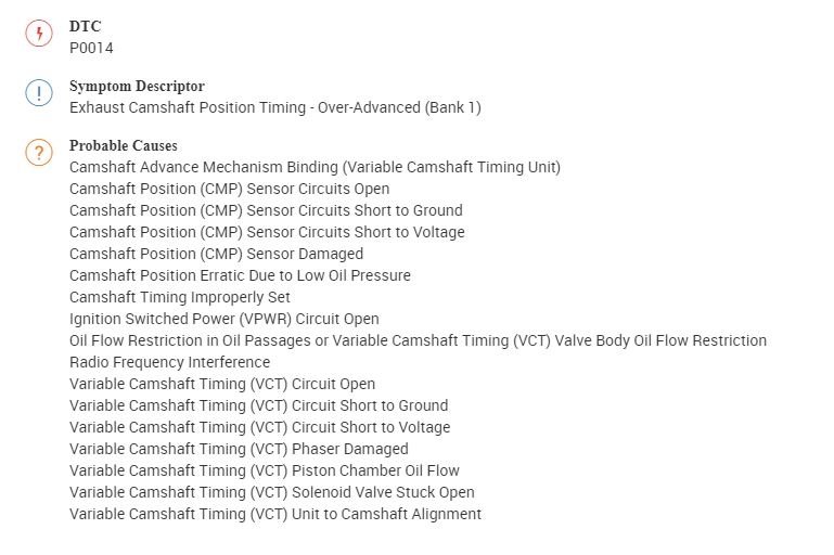
Aug 21, 2020 at 2:50 PM
(Merged)
Need the position for the sensor listed above for bank 1, passenger side.
Aug 21, 2020 at 2:50 PM
(Merged)
Good afternoon,
Is it the intake or exhaust cam sensor? There is one for each.
Why are you replacing it? They are not common failures. Do you have a code? If you do, can you give me the code so I can help you track down the failure?
Roy
Is it the intake or exhaust cam sensor? There is one for each.
Why are you replacing it? They are not common failures. Do you have a code? If you do, can you give me the code so I can help you track down the failure?
Roy
Image (Click to enlarge)
Aug 21, 2020 at 2:50 PM
(Merged)
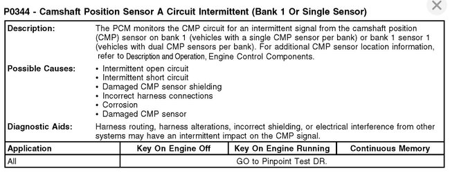
Codes P0340 and P0344.
Aug 21, 2020 at 2:50 PM
(Merged)
340 possibilities. I listed the possibilities below. It looks more electrical than a sensor.
If you have a scan tool, you can monitor the cam sensor readings while the engine is running to see if there is a signal being sent to the PCM.
Roy
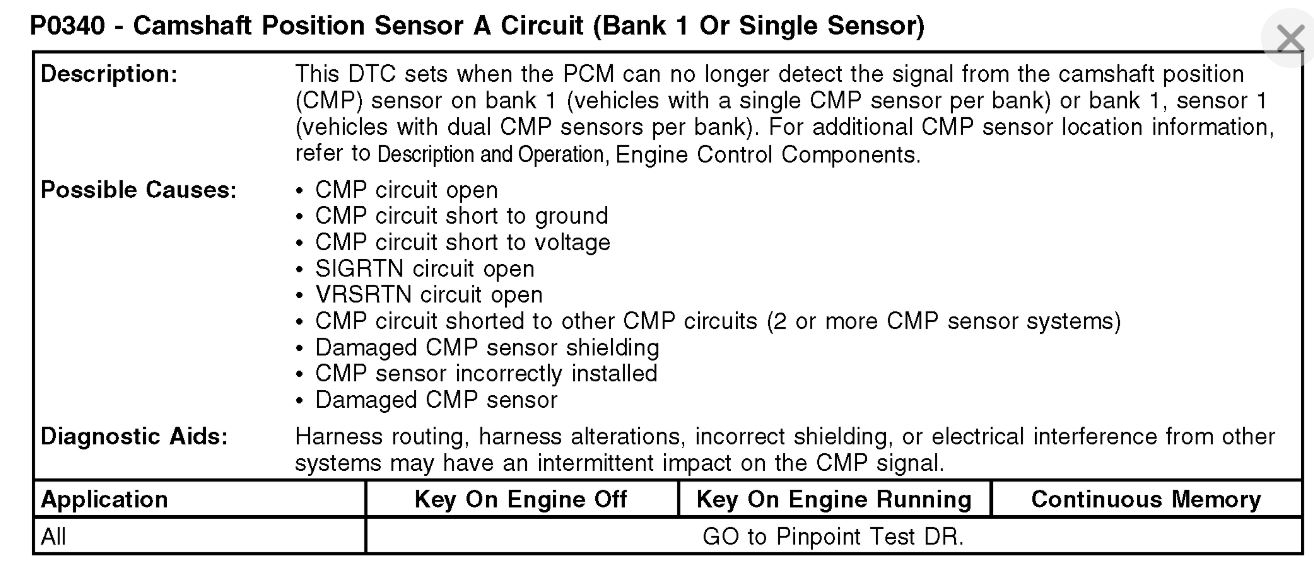
Symptom/DTC P0340
Descriptor
Camshaft Position Sensor A Circuit (Bank 1 Or Single Sensor)
Probable Causes
Camshaft Position (CMP) Circuit Open
Camshaft Position (CMP) Circuit Short to Ground
Camshaft Position (CMP) Circuit Short to Voltage
Camshaft Position (CMP) Circuit Shorted to Other CMP Circuits (2 or More CMP Sensor Systems)
Camshaft Position (CMP) Sensor Damaged
Camshaft Position (CMP) Sensor Incorrectly Installed
Camshaft Position (CMP) Sensor Shielding Damaged
Signal Return (SIGRTN) Circuit Open
Variable Reluctance Sensor Return (VRSRTN) Circuit Open
344
Symptom/DTC P0344
Descriptor
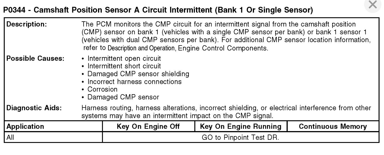
Camshaft Position Sensor A Circuit Intermittent (Bank 1 Or Single Sensor)
Probable Causes
Camshaft Position (CMP) Sensor Damaged
Camshaft Position (CMP) Sensor Shielding Damaged
Corrosion
Harness Connections Incorrect
Intermittent Open Circuit
Intermittent Short Circuit
Flow chart for the codes.
DR: Camshaft Position (CMP) Sensor
DR: Introduction See: Computers and Control Systems > Diagnostic Trouble Code Tests and Associated Procedures > DR: Camshaft Position (CMP) Sensor - Introduction
DR1 CHECK FOR DIAGNOSTIC TROUBLE CODES (DTCS)
Are DTCs P0340, P0341, P0344, P0345, P0346, P0349, P0365, P0366, P0369, P0390, P0391, or P0394 present?
Yes
For vehicles with DTCs and a no crank or no start symptom, GO to DR9.
For all others, GO to DR2.
No
For symptoms without DTCs, GO to DR2.
For all others, DISREGARD the current diagnostic trouble code (DTC) at this time. DIAGNOSE the next DTC. GO to Section 4, Diagnostic Trouble Code (DTC) Charts and Descriptions See: Computers and Control Systems > Diagnostic Trouble Code Tests and Associated Procedures > Diagnostic Trouble Code (DTC) Charts and Descriptions.
DR2 CLEAR AND ATTEMPT TO RETRIEVE THE DTC
Note:Consider the ignition system, alternator noise, radio frequency interference and crankshaft position (CKP) sensor concerns if DTCs P0340, P0341, P0344, P0345, P0346, P0349, P0365, P0366, P0369, P0390, P0391, or P0394 are present.
Note:For vehicles with variable camshaft timing (VCT), concerns with the engine oil level, oil filter, oil contamination, or the VCT system may cause camshaft positioning errors.
Ignition ON, engine OFF.
Clear the PCM DTCs.
Ignition ON, engine running.
Increase engine speed to greater than 1,500 RPM for 10 seconds. Repeat this 3 times.
Carry out the PCM self-test.
Are DTCs P0340, P0341, P0344, P0345, P0346, P0349, P0365, P0366, P0369, P0390, P0391 or P0394 present?
Yes
GO to DR3.
No
For symptoms without DTCs, RETURN to Section 3 See: Computers and Control Systems Diagnostic Trouble Code Tests and Associated Procedures > SECTION 3: Symptom Charts, Symptom Charts for further direction.
For all others, GO to Pinpoint Test Z See: Computers and Control Systems > Diagnostic Trouble Code Tests and Associated Procedures > Z: Intermittent - Introduction.
DR3 CHECK THE GENERATOR FOR EXCESSIVE ELECTRICAL NOISE
Note:If the generator/regulator is electrically noisy, the noise decreases when the B+ connector is disconnected.
Ignition ON, engine running.
Monitor the generator for an audible electric noise.
Ignition OFF.
Generator/regulator B+ connector disconnected.
Ignition ON, engine running.
With the engine running, determine if the generator noise remains steady, decreases or increases in volume.
Does the generator noise remain steady when the B+ connector is disconnected?
Yes
For DTCs P0341, P0346, P0366 or P0391, GO to DR20.
For F-150 3.5L and F-Series Super Duty 6.2L, GO to DR9.
For Escape 2.5L, Explorer GTDI 3.5L, F-150 5.0L, F-150 6.2L,
Flex GTDI 3.5L, Fusion 2.5L, MKS 3.5L, MKT 3.5L, Mustang 5.0L, Taurus
GTDI 3.5L and Transit Connect with DTCs P0340, P0344, P0345, or P0349,
GO to DR9.
For Edge 2.0L, Escape 1.6L, Escape 2.0L, Explorer 2.0L, Fiesta,
Focus, Fusion 1.6L, Fusion 2.0L, MKT 2.0L, MKZ 2.0L and Taurus 2.0L, GO
to DR12.
For all others, GO to DR4.
No
REFER to Charging System, to DIAGNOSE the generator is noisy symptom.
DR4 CHECK THE CMP SENSOR RESISTANCE
Note:Diagnose the suspect CMP sensor indicated by the DTC.
Note:Only measure the circuits that apply to the vehicle being diagnosed.
If you have a scan tool, you can monitor the cam sensor readings while the engine is running to see if there is a signal being sent to the PCM.
Roy
Symptom/DTC P0340
Descriptor
Camshaft Position Sensor A Circuit (Bank 1 Or Single Sensor)
Probable Causes
Camshaft Position (CMP) Circuit Open
Camshaft Position (CMP) Circuit Short to Ground
Camshaft Position (CMP) Circuit Short to Voltage
Camshaft Position (CMP) Circuit Shorted to Other CMP Circuits (2 or More CMP Sensor Systems)
Camshaft Position (CMP) Sensor Damaged
Camshaft Position (CMP) Sensor Incorrectly Installed
Camshaft Position (CMP) Sensor Shielding Damaged
Signal Return (SIGRTN) Circuit Open
Variable Reluctance Sensor Return (VRSRTN) Circuit Open
344
Symptom/DTC P0344
Descriptor
Camshaft Position Sensor A Circuit Intermittent (Bank 1 Or Single Sensor)
Probable Causes
Camshaft Position (CMP) Sensor Damaged
Camshaft Position (CMP) Sensor Shielding Damaged
Corrosion
Harness Connections Incorrect
Intermittent Open Circuit
Intermittent Short Circuit
Flow chart for the codes.
DR: Camshaft Position (CMP) Sensor
DR: Introduction See: Computers and Control Systems > Diagnostic Trouble Code Tests and Associated Procedures > DR: Camshaft Position (CMP) Sensor - Introduction
DR1 CHECK FOR DIAGNOSTIC TROUBLE CODES (DTCS)
Are DTCs P0340, P0341, P0344, P0345, P0346, P0349, P0365, P0366, P0369, P0390, P0391, or P0394 present?
Yes
For vehicles with DTCs and a no crank or no start symptom, GO to DR9.
For all others, GO to DR2.
No
For symptoms without DTCs, GO to DR2.
For all others, DISREGARD the current diagnostic trouble code (DTC) at this time. DIAGNOSE the next DTC. GO to Section 4, Diagnostic Trouble Code (DTC) Charts and Descriptions See: Computers and Control Systems > Diagnostic Trouble Code Tests and Associated Procedures > Diagnostic Trouble Code (DTC) Charts and Descriptions.
DR2 CLEAR AND ATTEMPT TO RETRIEVE THE DTC
Note:Consider the ignition system, alternator noise, radio frequency interference and crankshaft position (CKP) sensor concerns if DTCs P0340, P0341, P0344, P0345, P0346, P0349, P0365, P0366, P0369, P0390, P0391, or P0394 are present.
Note:For vehicles with variable camshaft timing (VCT), concerns with the engine oil level, oil filter, oil contamination, or the VCT system may cause camshaft positioning errors.
Ignition ON, engine OFF.
Clear the PCM DTCs.
Ignition ON, engine running.
Increase engine speed to greater than 1,500 RPM for 10 seconds. Repeat this 3 times.
Carry out the PCM self-test.
Are DTCs P0340, P0341, P0344, P0345, P0346, P0349, P0365, P0366, P0369, P0390, P0391 or P0394 present?
Yes
GO to DR3.
No
For symptoms without DTCs, RETURN to Section 3 See: Computers and Control Systems Diagnostic Trouble Code Tests and Associated Procedures > SECTION 3: Symptom Charts, Symptom Charts for further direction.
For all others, GO to Pinpoint Test Z See: Computers and Control Systems > Diagnostic Trouble Code Tests and Associated Procedures > Z: Intermittent - Introduction.
DR3 CHECK THE GENERATOR FOR EXCESSIVE ELECTRICAL NOISE
Note:If the generator/regulator is electrically noisy, the noise decreases when the B+ connector is disconnected.
Ignition ON, engine running.
Monitor the generator for an audible electric noise.
Ignition OFF.
Generator/regulator B+ connector disconnected.
Ignition ON, engine running.
With the engine running, determine if the generator noise remains steady, decreases or increases in volume.
Does the generator noise remain steady when the B+ connector is disconnected?
Yes
For DTCs P0341, P0346, P0366 or P0391, GO to DR20.
For F-150 3.5L and F-Series Super Duty 6.2L, GO to DR9.
For Escape 2.5L, Explorer GTDI 3.5L, F-150 5.0L, F-150 6.2L,
Flex GTDI 3.5L, Fusion 2.5L, MKS 3.5L, MKT 3.5L, Mustang 5.0L, Taurus
GTDI 3.5L and Transit Connect with DTCs P0340, P0344, P0345, or P0349,
GO to DR9.
For Edge 2.0L, Escape 1.6L, Escape 2.0L, Explorer 2.0L, Fiesta,
Focus, Fusion 1.6L, Fusion 2.0L, MKT 2.0L, MKZ 2.0L and Taurus 2.0L, GO
to DR12.
For all others, GO to DR4.
No
REFER to Charging System, to DIAGNOSE the generator is noisy symptom.
DR4 CHECK THE CMP SENSOR RESISTANCE
Note:Diagnose the suspect CMP sensor indicated by the DTC.
Note:Only measure the circuits that apply to the vehicle being diagnosed.
Images (Click to enlarge)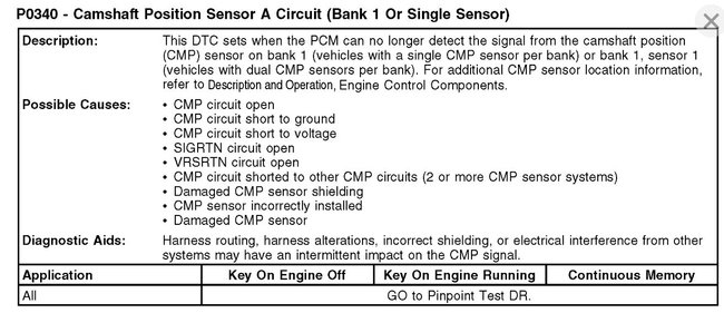
Aug 21, 2020 at 2:50 PM
(Merged)
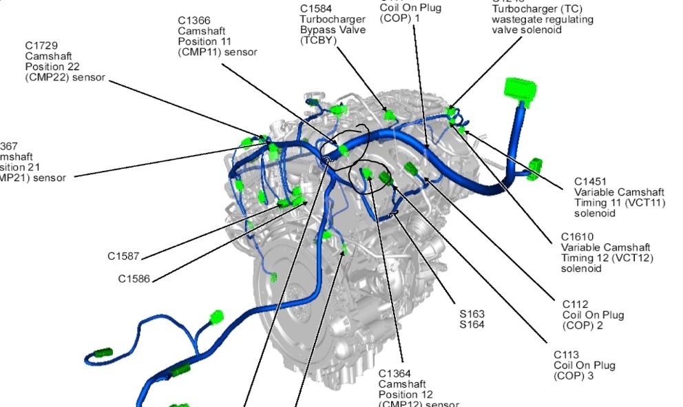
Trying to find camshaft position sensor locations?
Aug 21, 2020 at 5:36 PM
(Merged)

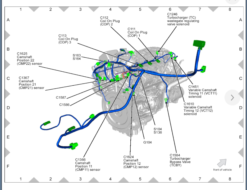
I attached the location of the CMP sensors. Let us know if you still can't find them and we will see if we can get some more info. Thanks
Image (Click to enlarge)
Aug 21, 2020 at 5:36 PM
(Merged)
Looking for the location of the two sensors listed above. I can't determine where they are and which side is which, nor can I find any diagram showing me where they are.
Aug 21, 2020 at 5:36 PM
(Merged)
The repair manual gives instructions to remove the transfer case, but I have done this from the top side. I pulled up a view with the valve cover off because there are no clear illustrations that show this, backside of the driver side head. One 8mm bolt holds each sensor in, so a shallow 1/4 drive 8mm socket and ratchet should get it done.
Image (Click to enlarge)
Aug 21, 2020 at 5:36 PM
(Merged)
Thank you very much!
Aug 21, 2020 at 5:36 PM
(Merged)
You are welcome!
Aug 21, 2020 at 5:36 PM
(Merged)
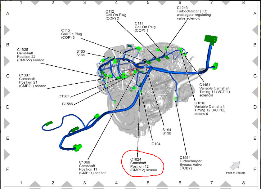
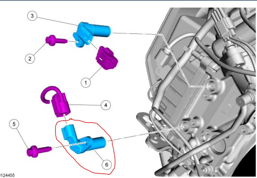
Had a P054a code . Can't find the location of the exhaust (B) camshaft position sensor bank1. Please send pictures or very good description of location. Thank you in advance.
Aug 21, 2020 at 5:36 PM
(Merged)

Hello, I'm Danny.
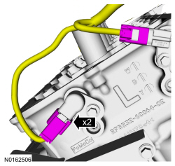
That sensor will be located on the right side (passenger) cylinder on the back of the cylinder head at the bottom. Here is a tutorial showing how to replace:
https://www.om2carpros.c/articles/camshaft-angle-sensor-replacement
I've attached pictures below, However this is the left side. Similar picture but yours will be on the opposite site.Circled in red.Hope this helps and thanks for using 2CarPros.
Images (Click to enlarge)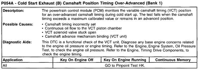


Aug 21, 2020 at 5:36 PM
(Merged)
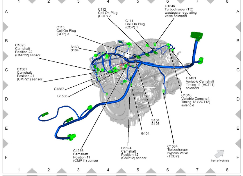
Trying to locate camshaft sensor bank 2 sensor B on a 2018 Ford F 150. Please help!
Dec 28, 2021 at 8:20 PM
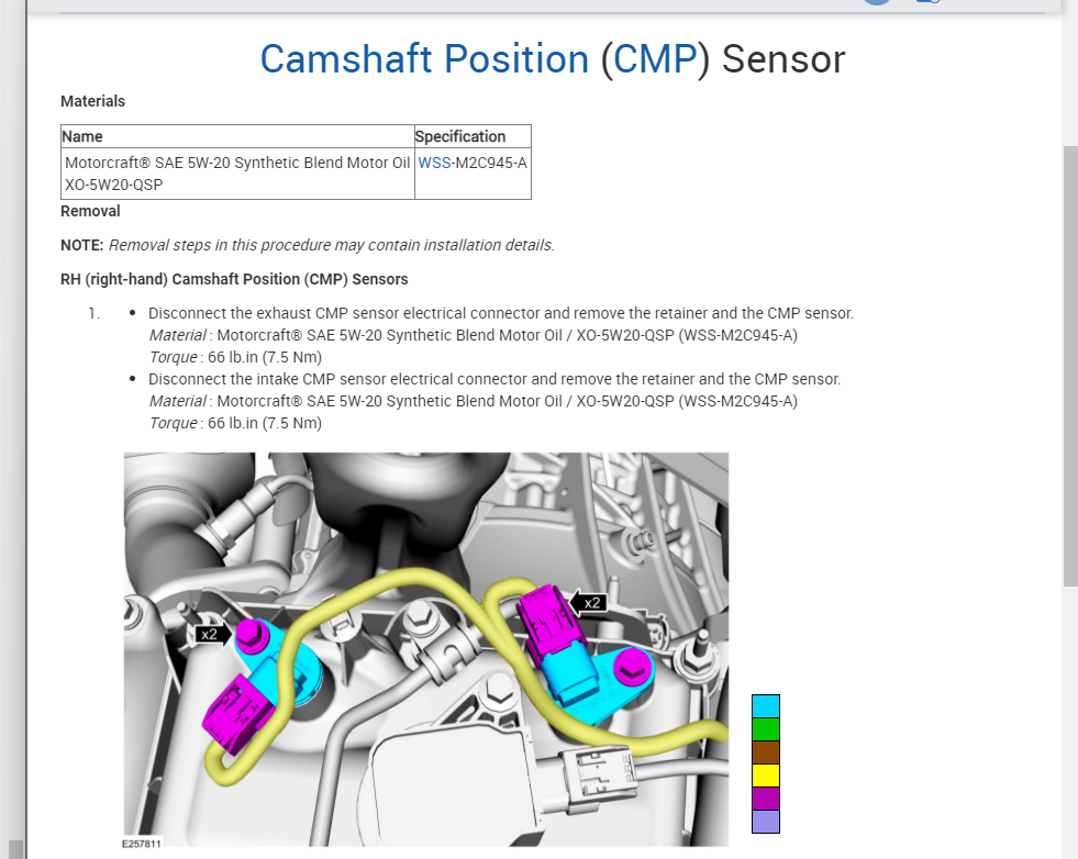
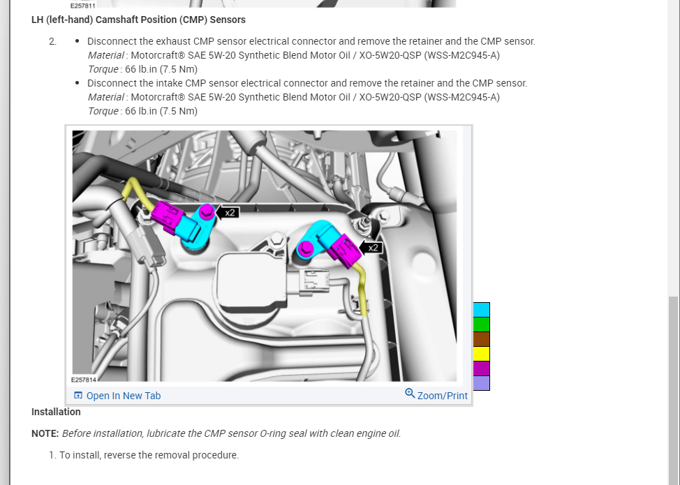
Can you be more specific on which engine? You have 5 options but more than likely you have a 5.0L so I attached the info on these sensors.
Plus, here is a guide that will help with this that has some good info:
https://www.2carpros.com/articles/camshaft-angle-sensor-replacement
Please see the info below and let me know what other questions you have. Thanks
Plus, here is a guide that will help with this that has some good info:
https://www.2carpros.com/articles/camshaft-angle-sensor-replacement
Please see the info below and let me know what other questions you have. Thanks
Images (Click to enlarge)

Dec 29, 2021 at 2:44 PM