Hi,
You are very welcome. I have a feeling that replacing the other sensor isn't going to remedy the problem. The code you have is specific to the sensor you already replaced.
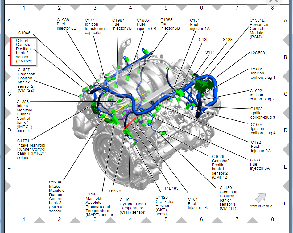
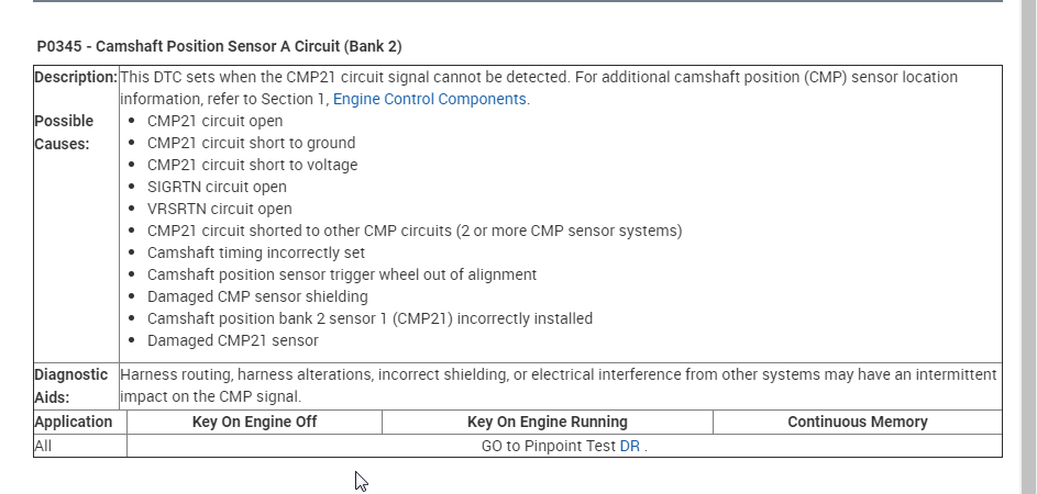
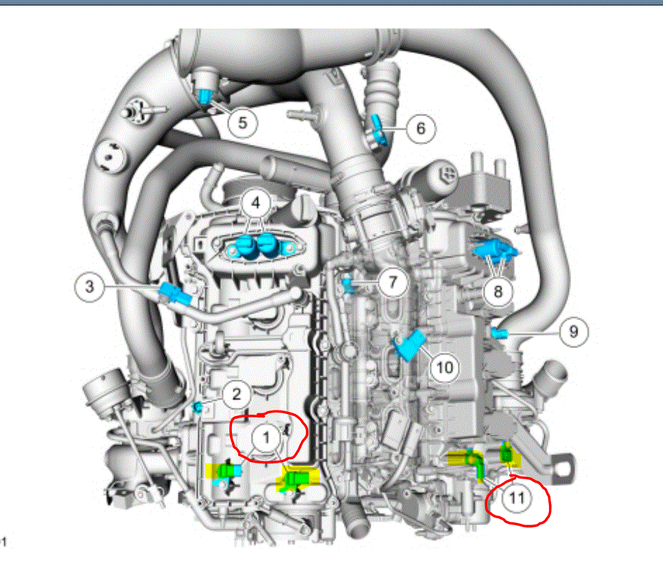
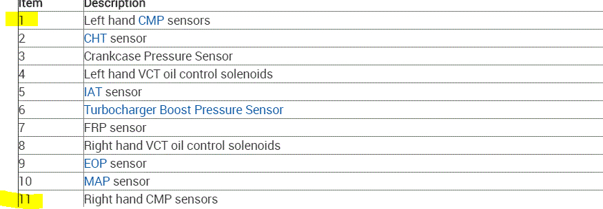
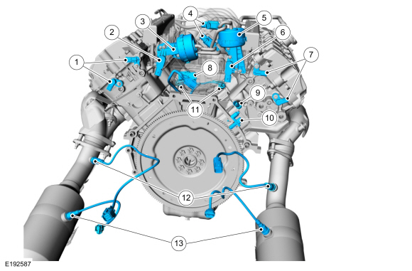
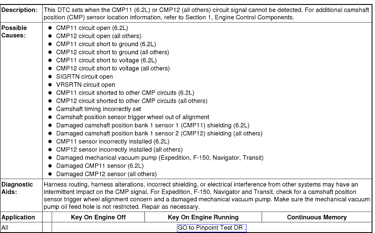
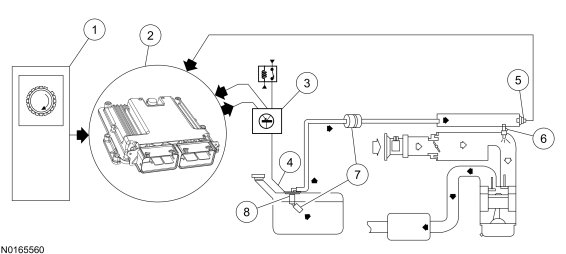
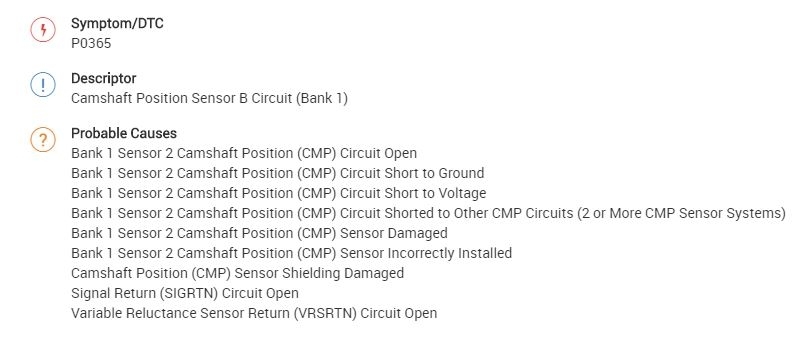
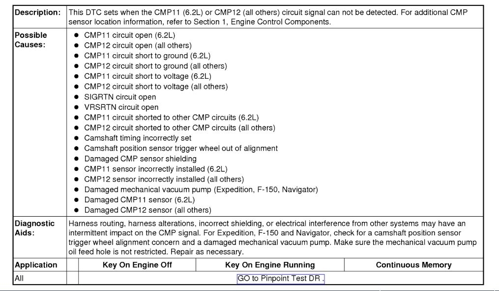
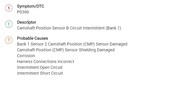
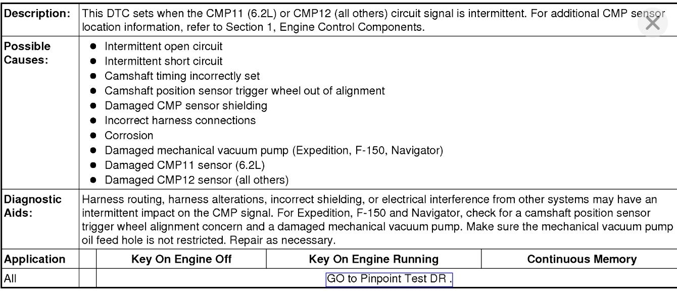
Here is the actual flow chart for diagnostics related to this code. I feel bad attaching it. LOL I don't how comfortable you feel doing it, but thought it may be of interest to you. If you look at that last pic I attached, it shows a list of things that can cause this code.
_________________________________
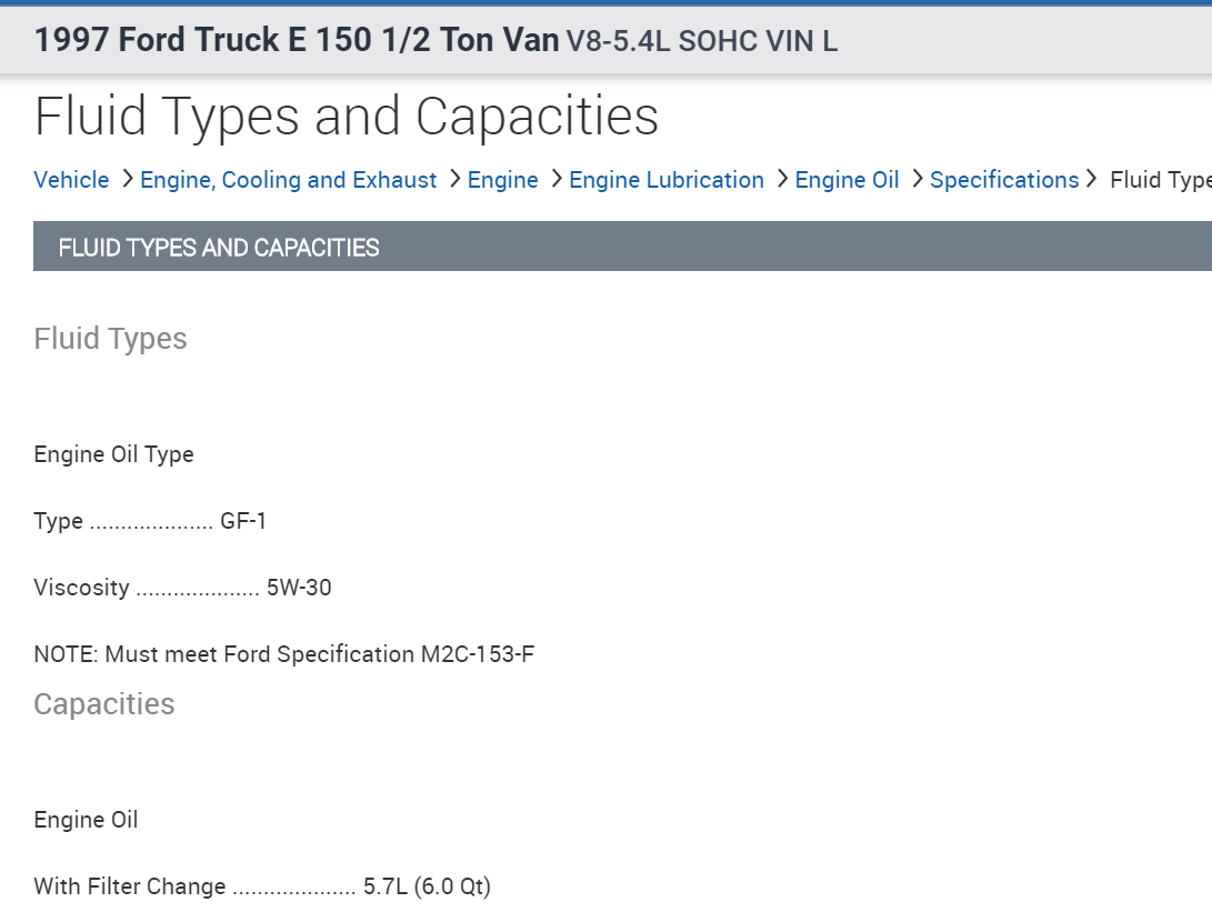
2015 Ford Truck F 150 4WD V6-2.7L Turbo
DR: Camshaft Position (CMP) Sensor - Pinpoint Test
Vehicle Powertrain Management Computers and Control Systems Testing and Inspection Diagnostic Trouble Code Tests and Associated Procedures Powertrain Control / Emission Diagnostics (PCED) SECTION 5: Pinpoint Tests DR: Camshaft Position (CMP) Sensor - Pinpoint Test
DR: CAMSHAFT POSITION (CMP) SENSOR - PINPOINT TEST
DR: Camshaft Position (CMP) Sensor
DR: Introduction See: Computers and Control Systems > Diagnostic Trouble Code Tests and Associated Procedures > DR: Camshaft Position (CMP) Sensor - Introduction
DR1 CHECK FOR DTCS
Are DTCs P0340, P0341, P0344, P0345, P0346, P0349, P0365, P0366, P0369, P0390, P0391, or P0394 present?
Yes
- For vehicles with DTCs and a no crank or no start symptom, GO to DR5
.
- For all others, GO to DR2
.
No
- For symptoms without DTCs, GO to DR2
.
- For all others, RETURN to Section 3 See: Computers and Control Systems > Diagnostic Trouble Code Tests and Associated Procedures > SECTION 3: Symptom Charts
, Symptom Charts for further direction.
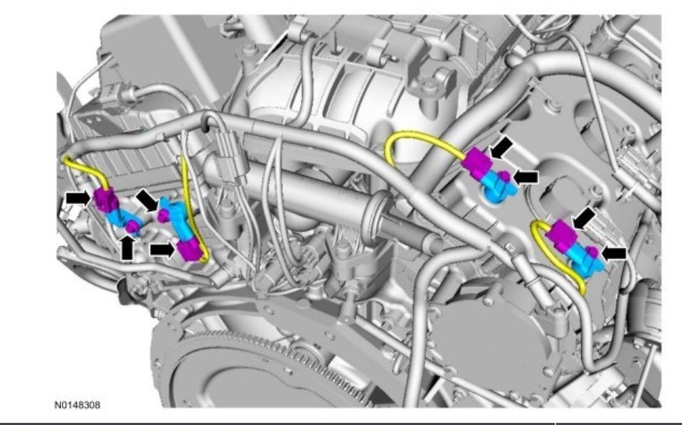
DR2 INSPECT THE HARNESS
- Ignition OFF.
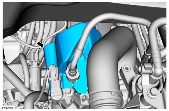
- Check the harness for routing, alterations, incorrect shielding, or electrical interference from other systems.
- Check the CMP connector for damage or corrosion.
Is a concern present?
Yes
- REPAIR as necessary.
- Clear the PCM DTCs. REPEAT the self-test.
No
- GO to DR3
.
DR3 CLEAR AND ATTEMPT TO RETRIEVE THE DTC
Note:Consider the ignition system, alternator noise, radio frequency interference and crankshaft position (CKP) sensor concerns if DTCs P0340, P0341, P0344, P0345, P0346, P0349, P0365, P0366, P0369, P0390, P0391, or P0394 are present.
Note:For vehicles with variable camshaft timing (VCT), concerns with the engine oil level, oil filter, oil contamination, or the VCT system may cause camshaft positioning errors.
- Ignition ON, engine OFF.
- Clear the PCM DTCs.
- Ignition ON, engine running.
- Increase engine speed to greater than 1,500 RPM for 10 seconds. Repeat this 3 times.
- Carry out the PCM self-test.
Are DTCs P0340, P0341, P0344, P0345, P0346, P0349, P0365, P0366, P0369, P0390, P0391 or P0394 present?
Yes
- GO to DR4
.
No
- For symptoms without DTCs, RETURN to Section 3 See: Computers and Control Systems > Diagnostic Trouble Code Tests and Associated Procedures > SECTION 3: Symptom Charts
, Symptom Charts for further direction.
- For all others, GO to Pinpoint Test Z See: Computers and Control Systems > Diagnostic Trouble Code Tests and Associated Procedures > Z: Intermittent - Introduction
.
DR4 CHECK THE GENERATOR FOR EXCESSIVE ELECTRICAL NOISE
Note:If the generator/regulator is electrically noisy, the noise decreases when the B+ connector is disconnected.
- Ignition ON, engine running.
- Monitor the generator for an audible electric noise.
- Ignition OFF.
- Generator/regulator B+ connector disconnected.
- Ignition ON, engine running.
- With the engine running, determine if the generator noise remains steady, decreases or increases in volume.
Does the generator noise remain steady when the B+ connector is disconnected?
Yes
- CONNECT the generator/regulator B+ connector.
- GO to DR5
.
No
- REFER to the Service Information Section 414-00, Charging System, to DIAGNOSE the generator is noisy symptom.
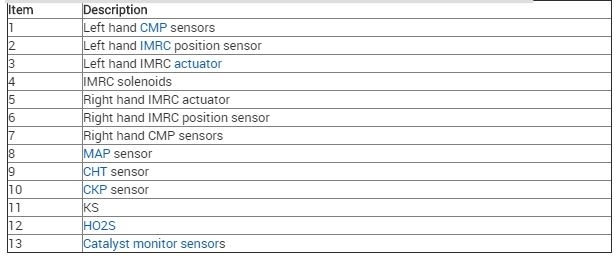
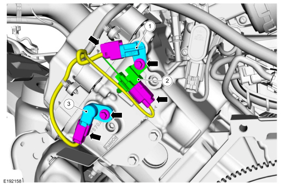
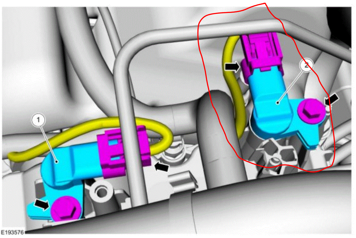
DR5 CHECK THE VOLTAGE TO THE CMP SENSOR
Note:Diagnose the suspect CMP sensor indicated by the DTC. For 2 pin VR type CMP sensor DTCs, GO to DR6.
- CMP Sensor connector disconnected.
- Ignition ON, engine OFF.
- For VBPWR CMP sensors,
- Measure the voltage between:
pic 1
- For VREF CMP sensors,
- Measure the voltage between:
pic 2
Is the voltage greater than 10.5 V on the VBPWR circuit or between 4.5 and 5.5 V on the VREF circuit?
Yes
- GO to DR7
.
No
- For Edge 2.0L,
- Escape/Kuga 1.6L,
- Escape/Kuga 2.0L,
- Explorer 2.0L,
- Fiesta,
- Focus,
- Fusion 1.5L,
- Fusion 1.6L,
- Fusion 2.0L,
- MKC,
- MKT 2.0L,
- MKZ 2.0L,
- Mustang 2.3L,
- Taurus 2.0L, and
- Transit Connect 1.6L, GO to Pinpoint Test C See: Computers and Control Systems > Diagnostic Trouble Code Tests and Associated Procedures > C: Reference Voltage (VREF) - Introduction
.
- For all others, REPAIR the open circuit.
- Clear the PCM DTCs. REPEAT the self-test.
DR6 CHECK THE CMP SENSOR RESISTANCE
Note:Diagnose the suspect CMP sensor indicated by the DTC.
- Ignition OFF.
- CMP Sensor connector disconnected.
- Measure the resistance between:
pic 3
Pic 4
Is the resistance within specification?
Yes
- GO to DR7
.
No
- INSTALL a new CMP sensor. REFER to the Service Information Section 303-14, Electronic Engine Controls.
- Clear the PCM DTCs. REPEAT the self-test.
DR7 CHECK THE CMP SENSOR CIRCUITS FOR AN OPEN
- PCM connector disconnected.
- Measure the resistance between:
pic 5
Are the resistances less than 5 ohms?
Yes
- GO to DR8
.
No
- REPAIR the open circuit. Clear the PCM DTCs. REPEAT the self-test.
DR8 CHECK THE CMP CIRCUIT FOR A SHORT
- Measure the resistance between:
pic 6
- Measure the resistance between:
pic 7
Are the resistances greater than 10K ohms?
Yes
- GO to DR9
.
No
- REPAIR the short circuit. Clear the PCM DTCs. REPEAT the self-test.
DR9 CHECK THE CMP CIRCUIT FOR A SHORT TO VOLTAGE
- Ignition ON, engine OFF.
- Measure the voltage between:
pic 8
Is any voltage present?
Yes
- REPAIR the short circuit. Clear the PCM DTCs. REPEAT the self-test.
No
- For E-Series,
- F-650 / F-750,
- F-Series Super Duty 6.8L, and
- Motorhome / Stripped Chassis / Step Van, GO to DR11
.
- For all others, GO to DR10
.
DR10 CHECK FOR VARIABLE CAMSHAFT TIMING (VCT) CONCERNS
Note:Only diagnose the bank indicated by the DTC.
- CMP Sensor connector connected.
- PCM connector connected.
- Check the VCT system for correct operation.
Is a concern present?
Yes
- REPAIR as necessary.
- Clear the PCM DTCs. REPEAT the self-test.
No
- GO to DR11
.
DR11 CHECK THE CMP SENSOR OPERATION
- Ignition OFF.
- CMP Sensor connector connected.
- PCM connector connected.
- Ignition ON, engine running.
- Access the PCM and monitor the SYNC (MODE) PID.
Does the engine start and does the SYNC PID read YES?
Yes
- GO to DR12
.
No
- INSTALL a new CMP sensor. REFER to the Service Information Section 303-14, Electronic Engine Controls.
- Clear the PCM DTCs. REPEAT the self-test.
DR12 CHECK FOR DTCS
- Carry out the PCM self-test.
Are any DTCs present?
Yes
- INSTALL a new CMP sensor. REFER to the Service Information Section 303-14, Electronic Engine Controls.
- Clear the PCM DTCs. REPEAT the self-test.
No
- The system is operating correctly at this time. The concern may have been caused by a loose or corroded connector.
- Clear the PCM DTCs. REPEAT the self-test.
_________________________________________________________
It's likely that you now hate me for attaching this. LOL Regardless, let me know what you find.
Take care,
Joe
Images (Click to enlarge)
Aug 21, 2020 at 2:50 PM
(Merged)