Feb 22, 2020 at 7:44 PM
intake air control valve?
1997 NISSAN TRUCK
Advertisement
Okay, I'll drive it about 10 or more miles to see what happens.
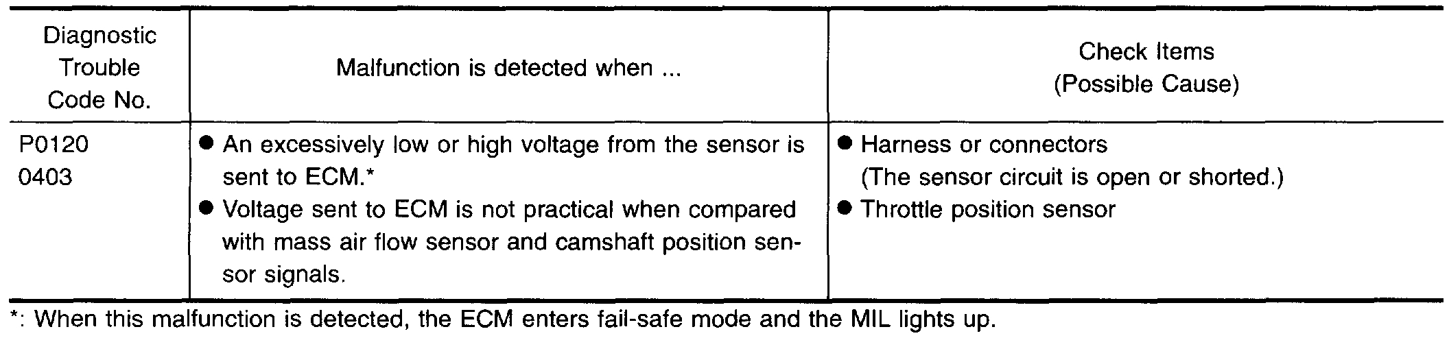
Joe, I drove it today and it ran good for a while but then it started acting up then I brought it home and took the MAF sensor out and cleaned it with MAF Sensor spray. I drove it tonight and it seems to be running better.It did not quit on me tonight . I checked the pending codes and they were P0100 - maf and P0120 P0120 is the generic OBD-II code which indicates that the Engine Control Module (ECM) has seen the TPS sensor circuit A output voltage going below or above the sensor's expected range, or is chattering when compared to TPS sensor circuit B.
What is your thoughts on this information. Thanks
What is your thoughts on this information. Thanks
Feb 23, 2020 at 5:39 PM
Advertisement

Since it is happening after you drive it for awhile, it seems it could be heat related. A bad connection or a sensor could be the issue. Here is the entire list regarding the P0120. If you page through it, it explains how to test the sensor and connection with the ECM. The last test is for the throttle position sensor. I would suggest doing the test, but I would do it when everything is warm and you are experiencing the issue.
The attached pics correlate with the directions.
________________-
1997 Nissan-Datsun Truck D21 Hardbody XE 2WD L4-2389cc 2.4L SOHC MFI (KA24E)
P0120
Vehicle ALL Diagnostic Trouble Codes ( DTC ) Testing and Inspection P Code Charts P0120
P0120
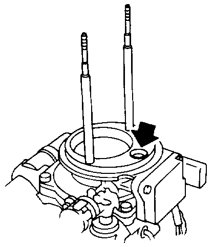
pic 1
pic 2
COMPONENT DESCRIPTION
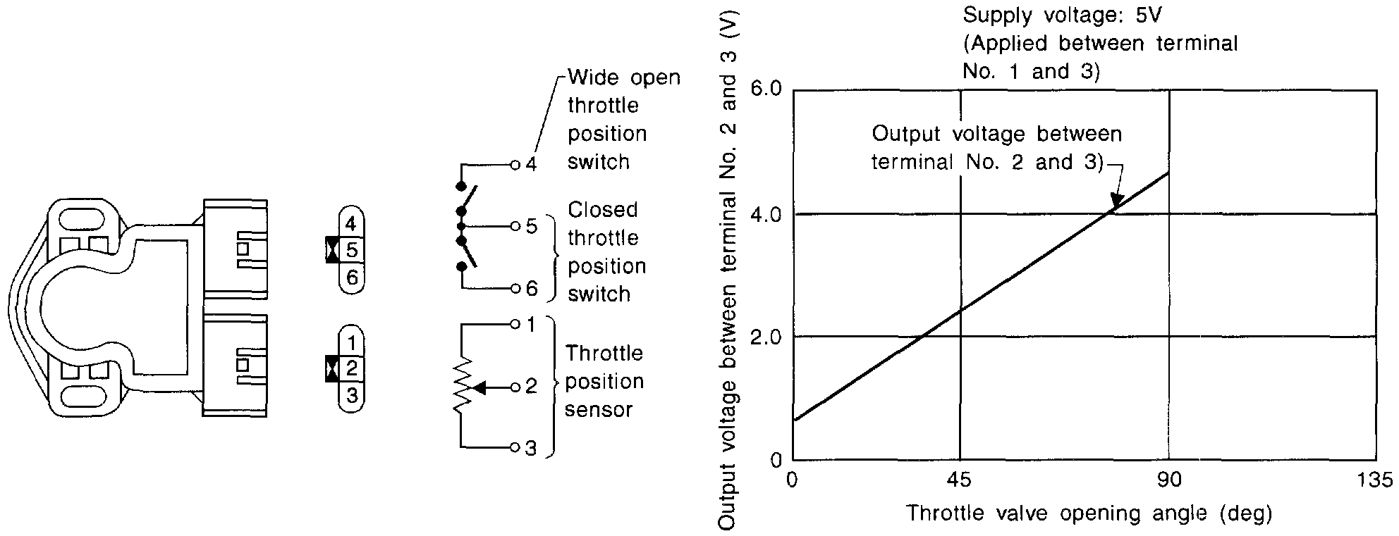
The throttle position sensor responds to the accelerator pedal movement. This sensor is a kind of potentiometer which transforms the throttle position into output voltage and emits the voltage signal to the ECM. In addition, the sensor detects the opening and closing speed of the throttle valve and feeds the voltage signal to the ECM.
Idle position of the throttle valve is determined by the ECM receiving the signal from the throttle position sensor. This controls engine operation such as fuel cut. The throttle position sensor unit contains a built-in "Wide open and closed throttle position switch".
pic 3
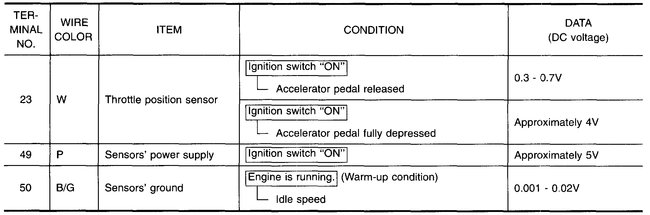
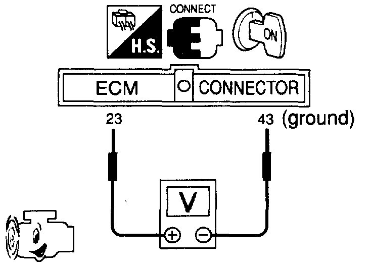
ECM TERMINALS AND REFERENCE VALUE
Specification data are reference values and are measured between each terminal and (43) (ECCS ground).
pic 4
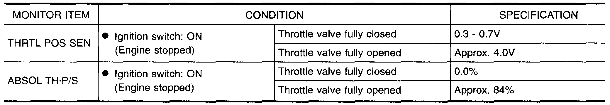
CONSULT REFERENCE VALUE IN DATA MONITOR MODE
Specification data are reference values
pic 5
ON BOARD DIAGNOSIS LOGIC
Engine operating condition in fail-safe mode
Throttle position will be determined based on the injected fuel amount and the engine speed.
Therefore, acceleration will be poor.
Condition / Driving Condition
When Engine is Idling / Normal
When accelerating / Poor accelerating
OVERALL FUNCTION CHECK
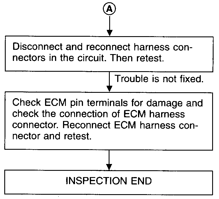
Use this procedure to check the overall function of the throttle position sensor circuit. During this check, a 1st trip DTC might not be confirmed.
With CONSULT
(1)Start engine and warm it up sufficiently.
(2)Turn ignition switch "OFF" and wait at least 7 seconds.
(3)Turn ignition switch "ON".
pic 6
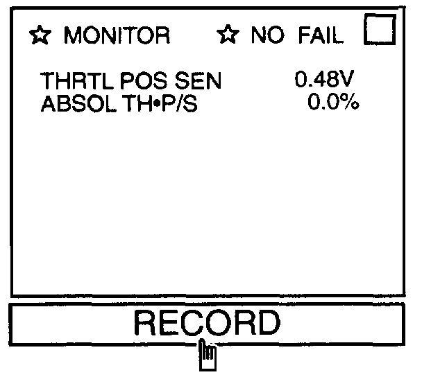
(4)Select "MANU TRIG" and "HI SPEED" in "DATA MONITOR" mode with CONSULT
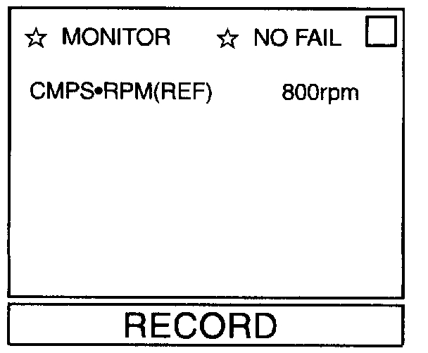
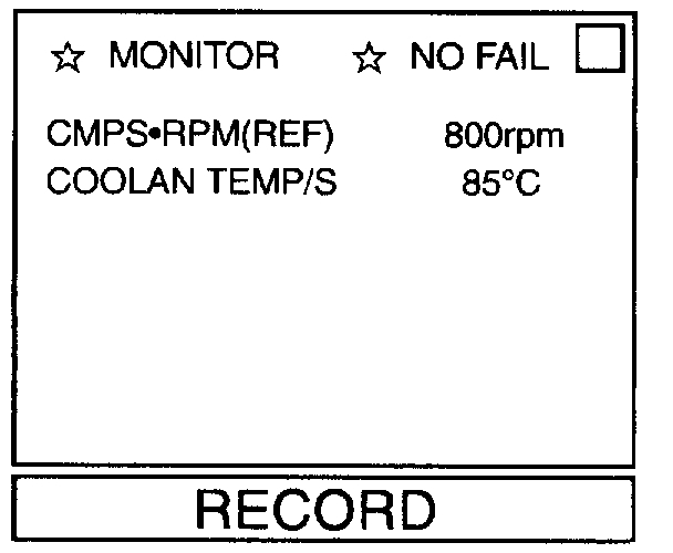
(5)Select "THRTL POS SEN" and "AE3SOL TH.P/S" in "DATA MONITOR" mode with CONSULT.
(6)Press RECORD on CONSULT SCREEN at the same time accelerator pedal is depressed.
pic 7
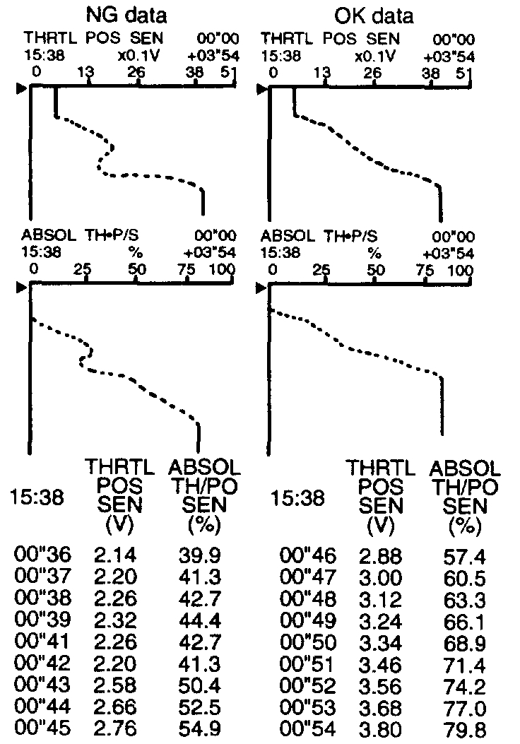
(7)Print out the recorded data and check the following:
- The voltage when accelerator pedal fully released is 0.3 - 0.7V.
- The voltage rise is linear in response to accelerator pedal depression.
- The voltage when accelerator pedal fully depressed is approximately 4V.
OR
Without CONSULT
(1)Start engine and warm it up sufficiently.
(2)Turn ignition switch "OFF" and wait at least 7 seconds.
(3)Turn ignition switch "ON".
pic 8
(4)Check the voltage between ECM terminal (23) and (43) (ground) and check the following:
- The voltage when accelerator pedal fully released is 0.3 - 0.7V.
- The voltage rise is linear in response to accelerator pedal depression.
- The voltage when accelerator pedal fully depressed is approximately 4V.
EC-TPS-01 Throttle Position (DTC P0120)
imageOpen In New TabZoom/Print
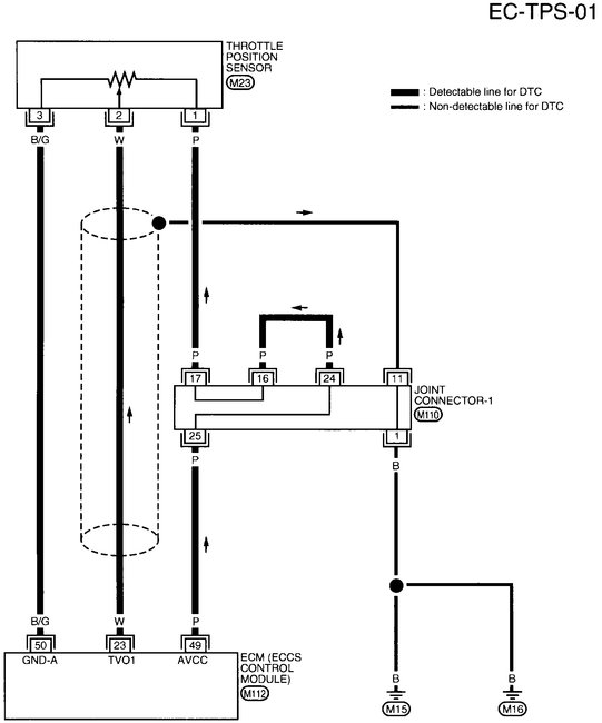
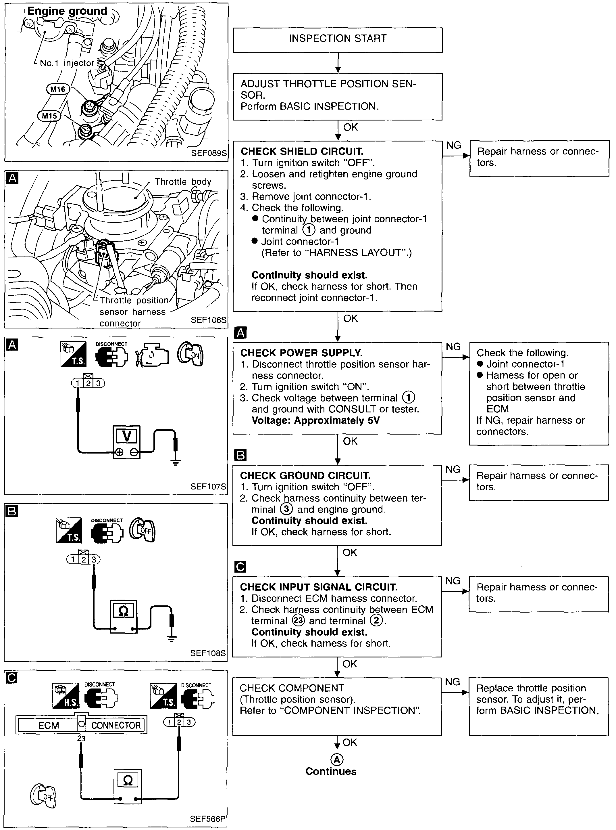
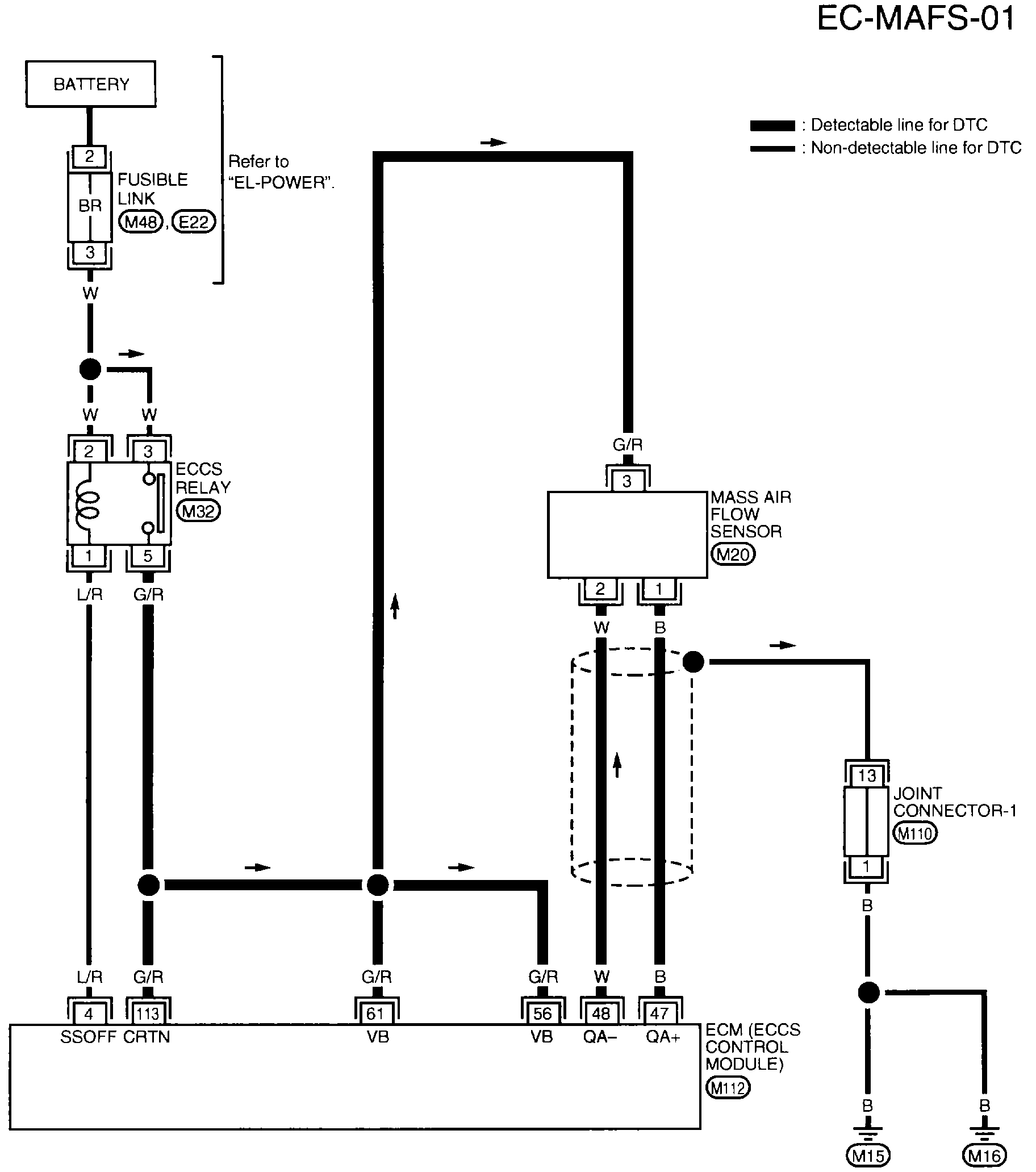
WIRING DIAGRAM
pic 9
pic 10
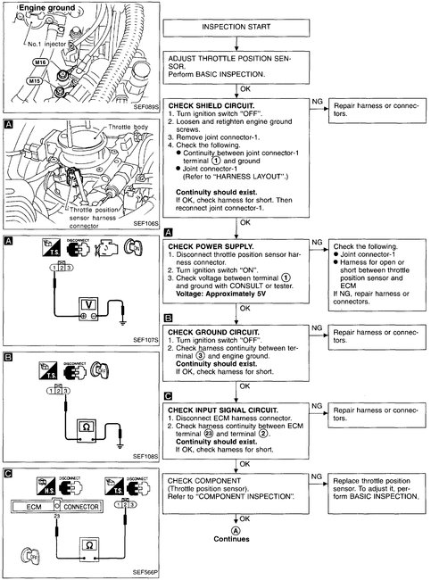
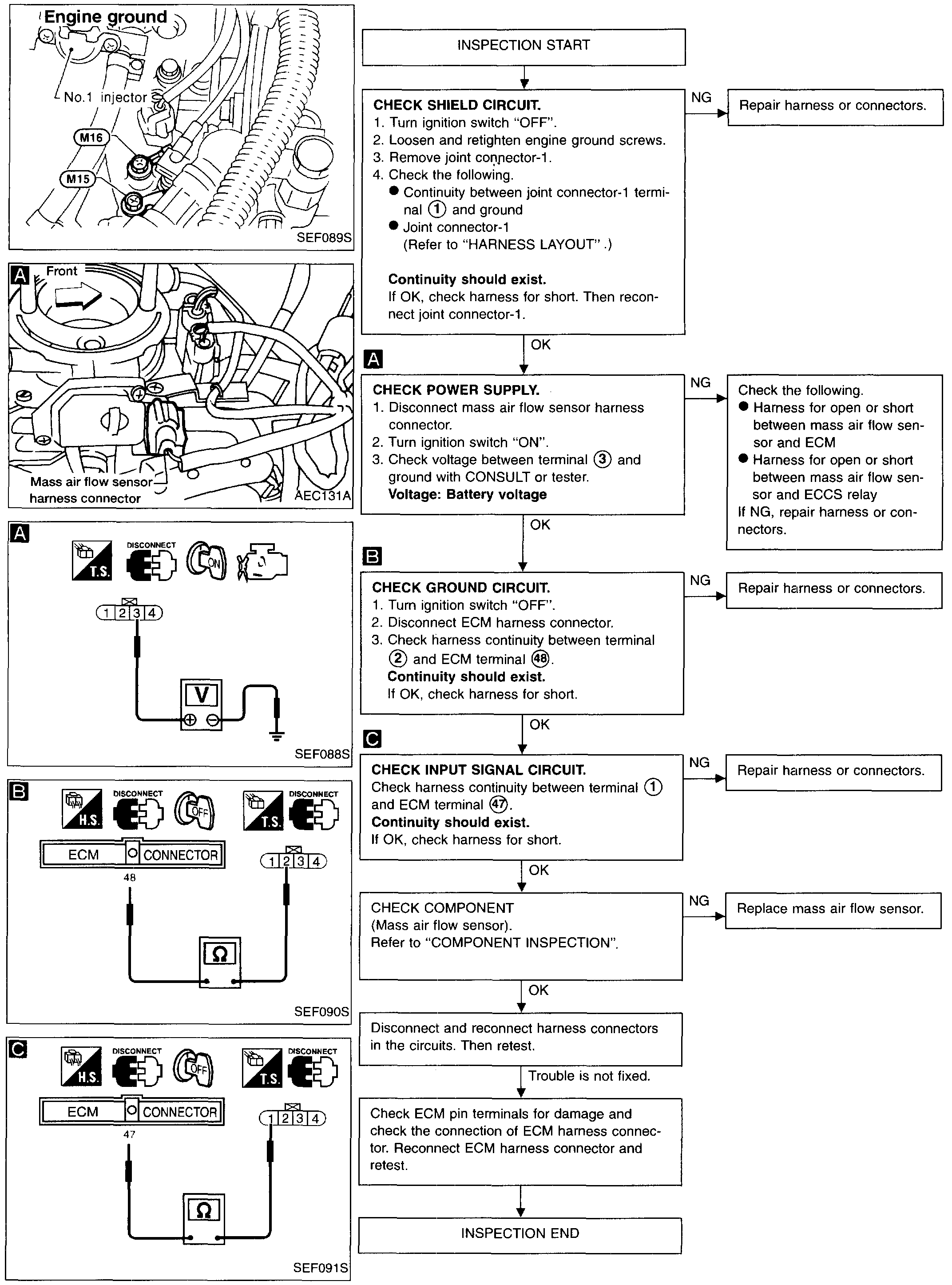
DIAGNOSTIC PROCEDURE
COMPONENT INSPECTION
Throttle Position Sensor
1. Start engine and warm it up sufficiently.
2. Turn ignition switch "OFF".
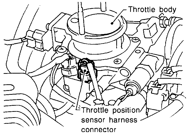
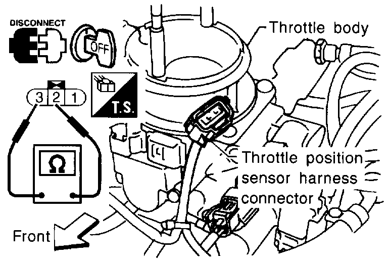
3. Disconnect throttle position sensor harness connector.
pic 11
4. Check resistance between terminals 2 and 3 while opening throttle valve manually.
Throttle Valve conditions / Resistance at 25°C(77°F)
Completely closed / Approximately 0.5 k Ohms
Partially open / 0.5 - 0.4 K Ohms
Completely open / Approximately 4.0 K Ohms
If NG, replace throttle position sensor.
To adjust throttle position sensor, perform "BASIC INSPECTION".
____________________________
Let me know the results.
Joe
The attached pics correlate with the directions.
________________-
1997 Nissan-Datsun Truck D21 Hardbody XE 2WD L4-2389cc 2.4L SOHC MFI (KA24E)
P0120
Vehicle ALL Diagnostic Trouble Codes ( DTC ) Testing and Inspection P Code Charts P0120
P0120
pic 1
pic 2
COMPONENT DESCRIPTION
The throttle position sensor responds to the accelerator pedal movement. This sensor is a kind of potentiometer which transforms the throttle position into output voltage and emits the voltage signal to the ECM. In addition, the sensor detects the opening and closing speed of the throttle valve and feeds the voltage signal to the ECM.
Idle position of the throttle valve is determined by the ECM receiving the signal from the throttle position sensor. This controls engine operation such as fuel cut. The throttle position sensor unit contains a built-in "Wide open and closed throttle position switch".
pic 3
ECM TERMINALS AND REFERENCE VALUE
Specification data are reference values and are measured between each terminal and (43) (ECCS ground).
pic 4
CONSULT REFERENCE VALUE IN DATA MONITOR MODE
Specification data are reference values
pic 5
ON BOARD DIAGNOSIS LOGIC
Engine operating condition in fail-safe mode
Throttle position will be determined based on the injected fuel amount and the engine speed.
Therefore, acceleration will be poor.
Condition / Driving Condition
When Engine is Idling / Normal
When accelerating / Poor accelerating
OVERALL FUNCTION CHECK
Use this procedure to check the overall function of the throttle position sensor circuit. During this check, a 1st trip DTC might not be confirmed.
With CONSULT
(1)Start engine and warm it up sufficiently.
(2)Turn ignition switch "OFF" and wait at least 7 seconds.
(3)Turn ignition switch "ON".
pic 6
(4)Select "MANU TRIG" and "HI SPEED" in "DATA MONITOR" mode with CONSULT
(5)Select "THRTL POS SEN" and "AE3SOL TH.P/S" in "DATA MONITOR" mode with CONSULT.
(6)Press RECORD on CONSULT SCREEN at the same time accelerator pedal is depressed.
pic 7
(7)Print out the recorded data and check the following:
- The voltage when accelerator pedal fully released is 0.3 - 0.7V.
- The voltage rise is linear in response to accelerator pedal depression.
- The voltage when accelerator pedal fully depressed is approximately 4V.
OR
Without CONSULT
(1)Start engine and warm it up sufficiently.
(2)Turn ignition switch "OFF" and wait at least 7 seconds.
(3)Turn ignition switch "ON".
pic 8
(4)Check the voltage between ECM terminal (23) and (43) (ground) and check the following:
- The voltage when accelerator pedal fully released is 0.3 - 0.7V.
- The voltage rise is linear in response to accelerator pedal depression.
- The voltage when accelerator pedal fully depressed is approximately 4V.
EC-TPS-01 Throttle Position (DTC P0120)
imageOpen In New TabZoom/Print
WIRING DIAGRAM
pic 9
pic 10
DIAGNOSTIC PROCEDURE
COMPONENT INSPECTION
Throttle Position Sensor
1. Start engine and warm it up sufficiently.
2. Turn ignition switch "OFF".
3. Disconnect throttle position sensor harness connector.
pic 11
4. Check resistance between terminals 2 and 3 while opening throttle valve manually.
Throttle Valve conditions / Resistance at 25°C(77°F)
Completely closed / Approximately 0.5 k Ohms
Partially open / 0.5 - 0.4 K Ohms
Completely open / Approximately 4.0 K Ohms
If NG, replace throttle position sensor.
To adjust throttle position sensor, perform "BASIC INSPECTION".
____________________________
Let me know the results.
Joe
Images (Click to enlarge)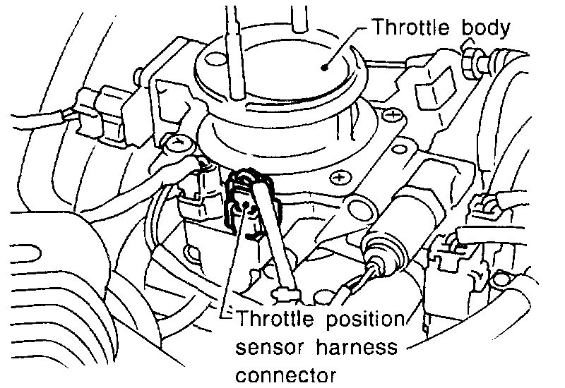


Feb 23, 2020 at 8:00 PM
it will be a few days, we got rain. thank you
Feb 24, 2020 at 1:00 PM
I drove my truck tonight and it never quit or even tried to quit, it missed a little bit when I drove it but maybe the problem is in the gas, weird things happening. I will try it for a day or two and see what happens, then if I have to I'll check the things you recommended yesterday . Thanks for your help.
Feb 24, 2020 at 7:06 PM
Sounds like a plan. Take care and let me know the results.
Joe
Joe
Feb 24, 2020 at 8:34 PM
I drove it about 20 miles today and the truck ran fine, then tonight it started acting up on me, I raised the hood and the fuel pump pressure was only showing 22 psi , so it looks like I'll be installing the fuel pump I already have. Seems you mentioned that to me but the pressures were showing good as long as the truck was idling but I guess the pressures changed when I started driving it. Not sure when I'll get it installed.
Feb 25, 2020 at 6:00 PM
It sounds like a good idea. If pressure is low, that's an issue. Here are the directions for removal of the tank and the pump. All pics correlate with the directions.
________________________________________
1997 Nissan-Datsun Truck D21 Hardbody XE 2WD L4-2389cc 2.4L SOHC MFI (KA24E)
Procedures
Vehicle Powertrain Management Fuel Delivery and Air Induction Fuel Tank Service and Repair Procedures
PROCEDURES
WARNING:
When replacing fuel line parts, be sure to observe the following:
- Put a "CAUTION: FLAMMABLE" sign in workshop.
- Do not smoke while servicing fuel system. Keep open flames and sparks away from work area.
- Furnish workshop with a CO2 fire extinguisher.
CAUTION:
- Before removing fuel line parts, carry out the following procedures:
a. Put drained fuel in an explosion-proof container and put the lid on securely.
b. Release fuel pressure from fuel line. Refer to ("Fuel Pressure Release").
c. Disconnect battery ground cable.
- When installing fuel check valve, install it in the correct direction.
- Always replace O-ring with a new one.
- Do not kink or twist tubes and hoses during installation.
- To avoid damaging hoses, do not tighten hose clamps excessively.
- After installing tubes, run engine and check for fuel leaks at connections.
- Use only a genuine fuel filler cap as a replacement. If an incorrect fuel filler cap is used, the MIL may turn on.
pic 1
REMOVAL
CAUTION:
- Do not disconnect any fuel line unless absolutely necessary.
- Plug hose and pipe openings to prevent entry of dust or dirt.
1. Release fuel pressure. Refer to ("Fuel Pressure Release").
2. Disconnect battery ground cable.
3. Drain fuel from fuel tank.
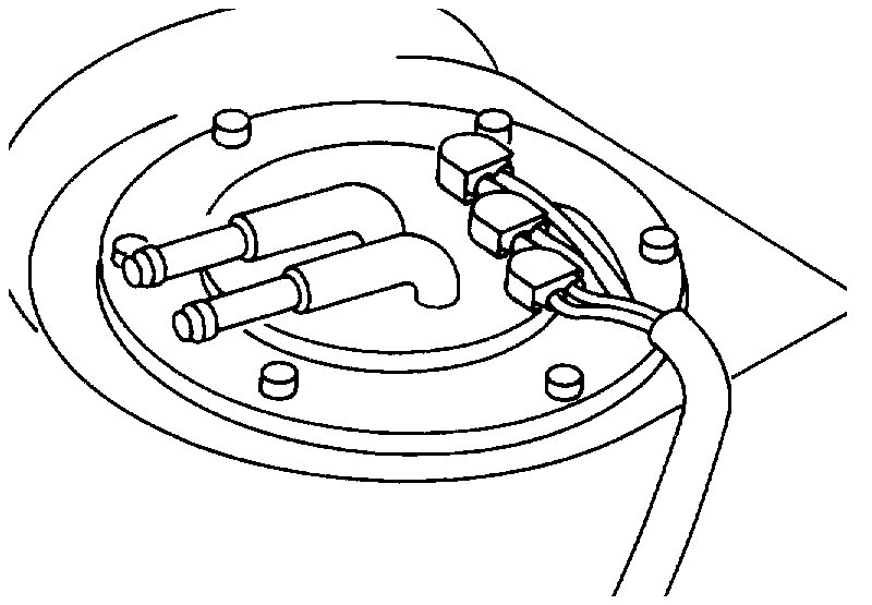
pic 2
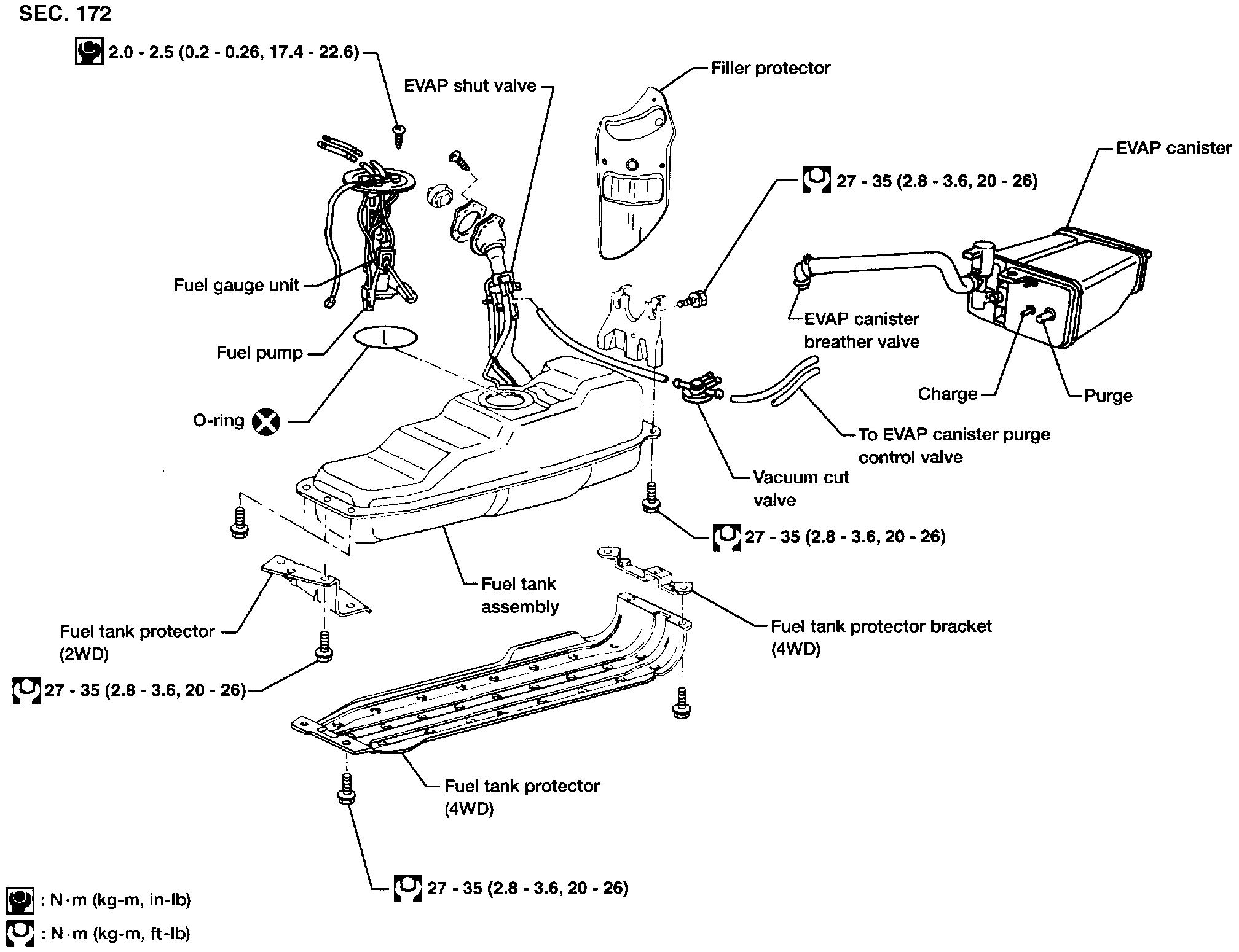
4. Disconnect electrical connector.
5. Remove filler protector.
6. Disconnect filler tubes, fuel supply tube and fuel return tube.
pic 3
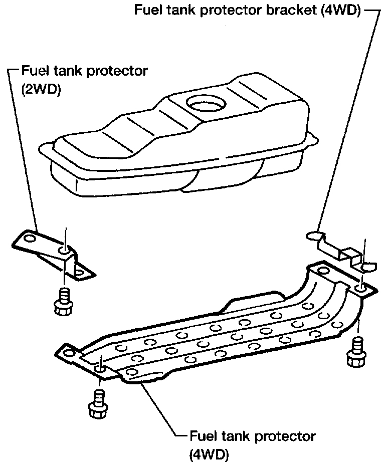
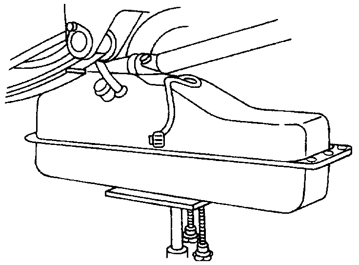
7. Remove fuel tank protector.
pic 4
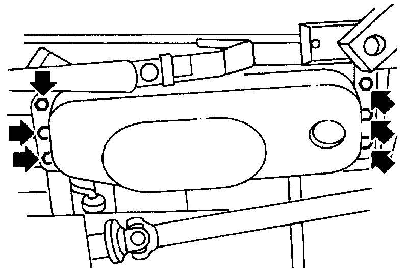
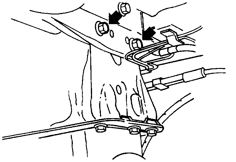
8. Remove six fuel tank mounting bolts while supporting fuel tank.
pic 5
9. Remove rear fuel tank mounting bracket.
pic 6
10. Remove fuel tank.
INSTALLATION
INSTALLATION HINT: To install, reverse the removal procedure.
CAUTION:
- Do not kink or twist hoses and tubes during installation.
- To avoid damaging hoses, do not tighten hose clamps excessively.
- Tighten bolts to specified torque.
- After installation, run engine and check for leaks at connections.
______________________________
1997 Nissan-Datsun Truck D21 Hardbody XE 2WD L4-2389cc 2.4L SOHC MFI (KA24E)
Procedures
Vehicle Powertrain Management Fuel Delivery and Air Induction Fuel Pump Service and Repair Procedures
PROCEDURES
Pic 7
REMOVAL
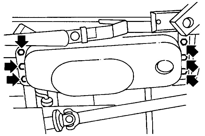
1. Remove fuel tank.
2. Disconnect fuel supply tube, fuel return tube and electrical connector.
3. Remove the six screws.
pic 8
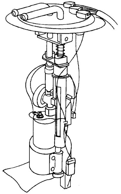
4. Remove fuel pump and gauge.
INSTALLATION
Installation Hint: To install, reverse the removal procedure.
CAUTION:
- Tighten bolts to specified torque.
2.0 - 2.5 N-m (0.20 - 0.26 kg-m, 17.4 - 22.6 in-lb)
- Always replace O-ring with a new one.
- After installation, run engine and check for leaks at connections.
__________________
Hope this helps.
Joe
________________________________________
1997 Nissan-Datsun Truck D21 Hardbody XE 2WD L4-2389cc 2.4L SOHC MFI (KA24E)
Procedures
Vehicle Powertrain Management Fuel Delivery and Air Induction Fuel Tank Service and Repair Procedures
PROCEDURES
WARNING:
When replacing fuel line parts, be sure to observe the following:
- Put a "CAUTION: FLAMMABLE" sign in workshop.
- Do not smoke while servicing fuel system. Keep open flames and sparks away from work area.
- Furnish workshop with a CO2 fire extinguisher.
CAUTION:
- Before removing fuel line parts, carry out the following procedures:
a. Put drained fuel in an explosion-proof container and put the lid on securely.
b. Release fuel pressure from fuel line. Refer to ("Fuel Pressure Release").
c. Disconnect battery ground cable.
- When installing fuel check valve, install it in the correct direction.
- Always replace O-ring with a new one.
- Do not kink or twist tubes and hoses during installation.
- To avoid damaging hoses, do not tighten hose clamps excessively.
- After installing tubes, run engine and check for fuel leaks at connections.
- Use only a genuine fuel filler cap as a replacement. If an incorrect fuel filler cap is used, the MIL may turn on.
pic 1
REMOVAL
CAUTION:
- Do not disconnect any fuel line unless absolutely necessary.
- Plug hose and pipe openings to prevent entry of dust or dirt.
1. Release fuel pressure. Refer to ("Fuel Pressure Release").
2. Disconnect battery ground cable.
3. Drain fuel from fuel tank.
pic 2
4. Disconnect electrical connector.
5. Remove filler protector.
6. Disconnect filler tubes, fuel supply tube and fuel return tube.
pic 3
7. Remove fuel tank protector.
pic 4
8. Remove six fuel tank mounting bolts while supporting fuel tank.
pic 5
9. Remove rear fuel tank mounting bracket.
pic 6
10. Remove fuel tank.
INSTALLATION
INSTALLATION HINT: To install, reverse the removal procedure.
CAUTION:
- Do not kink or twist hoses and tubes during installation.
- To avoid damaging hoses, do not tighten hose clamps excessively.
- Tighten bolts to specified torque.
- After installation, run engine and check for leaks at connections.
______________________________
1997 Nissan-Datsun Truck D21 Hardbody XE 2WD L4-2389cc 2.4L SOHC MFI (KA24E)
Procedures
Vehicle Powertrain Management Fuel Delivery and Air Induction Fuel Pump Service and Repair Procedures
PROCEDURES
Pic 7
REMOVAL
1. Remove fuel tank.
2. Disconnect fuel supply tube, fuel return tube and electrical connector.
3. Remove the six screws.
pic 8
4. Remove fuel pump and gauge.
INSTALLATION
Installation Hint: To install, reverse the removal procedure.
CAUTION:
- Tighten bolts to specified torque.
2.0 - 2.5 N-m (0.20 - 0.26 kg-m, 17.4 - 22.6 in-lb)
- Always replace O-ring with a new one.
- After installation, run engine and check for leaks at connections.
__________________
Hope this helps.
Joe
Images (Click to enlarge)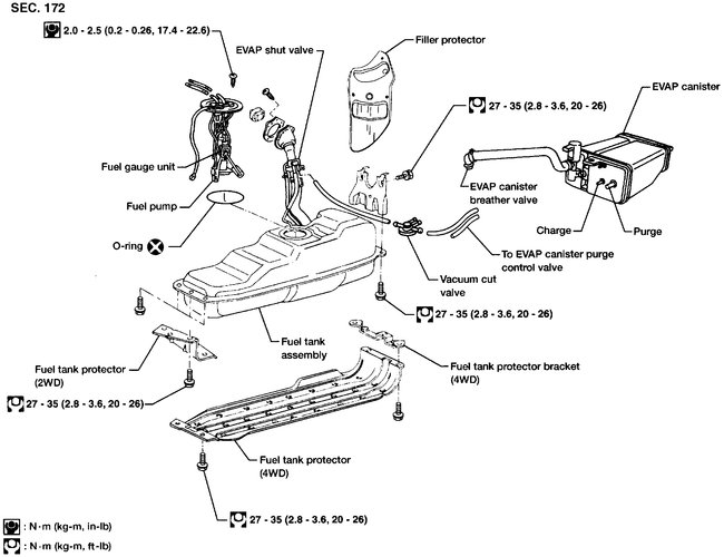


Feb 25, 2020 at 6:37 PM
Thanks, it might a few days since we suppose to get snow plus I just filled my tank up today and some 5 gallon jugs and have nothing to siphon the gas into . Can't win for losing, lol.
Feb 26, 2020 at 10:39 AM
Not a problem. We are going to see the snow as well. Let me know when you get to it. I'm interested in knowing if that takes care of the issues.
Joe
Joe
Feb 26, 2020 at 5:18 PM
You're going to be surprised at what I'm telling you, I rechecked the screw on connection on the T fitting I had installed to use a gas gauge and the darn thing had loosened up and was not giving me the proper pressures, I re-tightened it and now it's showing the correct pressures and I drove it today and it ran pretty good and also it ran pretty good tonight. It still isn't 100% right but it might be in the gas or some other little sensor .I am thinking that the fuel pump sock (screen) in the tank might be sucking together preventing the gas to flow.I need to install a fuel pump because this one is 22 years. old. I'll need to drive it some more and see what happens, thanks for your answers. I'll get back to you.
Feb 26, 2020 at 6:30 PM
If it was leaking fuel, that is certainly an issue. If, however, the pressure is within spec, there shouldn't be any issue with the sock or a need to replace it.
Drive it awhile and see how things go.
Take care and enjoy the snow.
Joe
Drive it awhile and see how things go.
Take care and enjoy the snow.
Joe
Feb 26, 2020 at 6:36 PM
I'm not sure if I told you or not but I received the Hitachi IACV brand that I ordered and if my truck keeps acting up I'm going to put this part on. If the IACV that's on it now has a slight delay (hesitation) that might be what is causing the problem. What's your thoughts on that ? Thanks
Feb 26, 2020 at 7:02 PM
The IACV really shouldn't cause a hesitation. It will, however, cause idle issues.
Joe
Joe
Feb 26, 2020 at 7:08 PM
I had my AurtoXray 7ooo Scanner connected today and I noticed that when I press my gas pedal the TPS on the screen doesn't show a percentage of the gas pedal being pressed, in other words shouldn't it show me that the gas pedal is pressed at 10%, 20% or some other percentage when I press the pedal when I' m idling the truck and if I press it WOT it should show me 100% ? What are your thoughts on that ? I haven't tried your suggestions yet, it's cold and snowing here probably there too.
Feb 28, 2020 at 2:51 PM
The scanner will not anything on the percentage at idle but it does when I drive it. I had the code p0100 come on again and I just ordered the MAF sensor, we'll see what this does.
Feb 28, 2020 at 7:31 PM
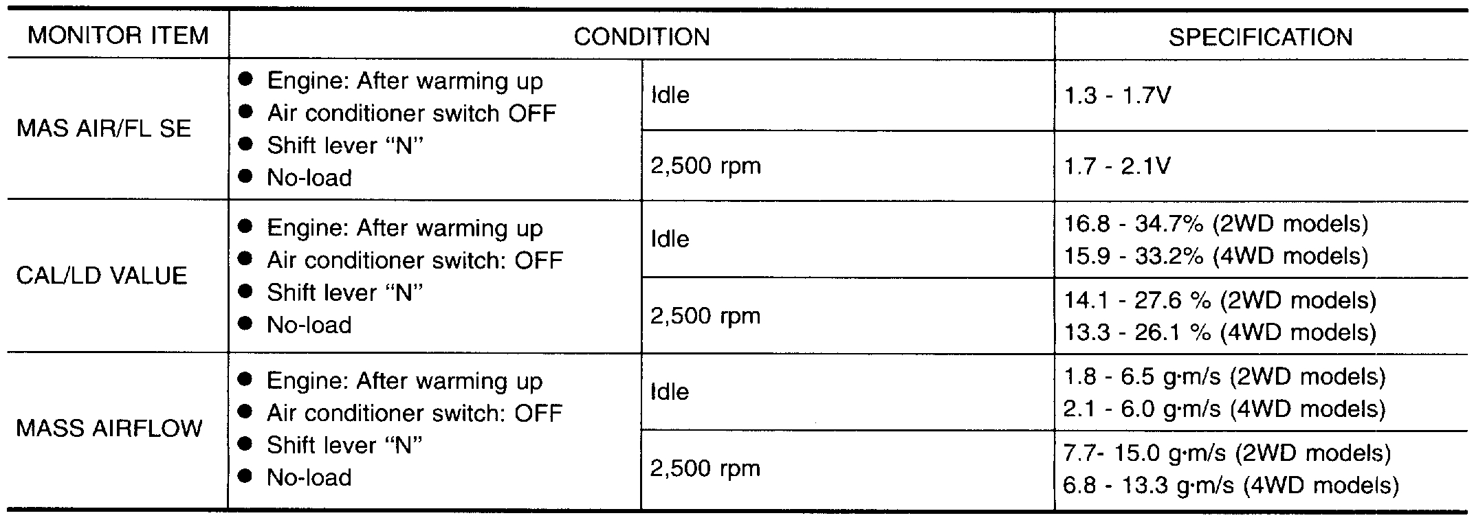
The MAF may be the problem. With your live data scanner, tell me what the readings are for the MAF at idle and at 2500 RPM's. At idle, they should be around 5 grams per second (G/S). When you get to around 2500 RPM's, it should be around 20 (G/S).
Let me know.
Joe
Let me know.
Joe
Feb 28, 2020 at 8:06 PM
My Autoxray 7000 scanner only shows it in lb/m ( lbs per minute ) , it does not show it G/S .
The other day it was showing MAF (lb/m ) .64 at about 1,000 rpms but drops as the idling comes down like it suppose to I assume. Does G/S stand for grains per second & lb/m mean pounds per minute ? I guess lb/m can be changed to G/S . I will try what you said today sometime.
Can I check that as soon as the truck is started or do I need to wait until the motor is warmed up or does it matter ? Here's what I found ,
Home: Kyle's ConverterKyle's CalculatorsKyle's Conversion Blog
Convert Pounds Per Minute to Grains Per Second
Kyle's Converter > Mass Flow > Pounds Per Minute > Pounds Per Minute to Grains Per Second
Pounds Per Minute (lbm/min) .64 = Grains Per Second (gr/s) =74.67
I'll get back to you later today if my truck will run, almost never got it home last night, it was missing so bad . I ordered one of those $20 MAF sensor probably made in China . I think that part should be in on Mar. 5th , it's coming from Calif. .
Feb 29, 2020 at 5:08 AM
Hi,
G/S stands for grams per second. At idle, it should be around 5. If your conversion is correct, (74.67), that is way off.
Joe
G/S stands for grams per second. At idle, it should be around 5. If your conversion is correct, (74.67), that is way off.
Joe
Feb 29, 2020 at 5:27 PM
Joe, that lb/m .64 was at idle, not at 2,500 rpm like you wanted me to have the rpm's. When I had the truck at 2,500 rpm's the MAF was 1.48 lb/m = g/s 11.18861179333 from the conversion chart.
Feb 29, 2020 at 6:42 PM
Okay, my mistake. The idle is good. At 2500 it's a bit off.
Let me know.
Joe
Let me know.
Joe
Feb 29, 2020 at 6:56 PM
Joe, what's the EGI relay for ? Does EGI stand for Electronic Gas Injection? if it does couldn't that be causing me problems? My truck has this relay near the fuel pump relay.
Feb 29, 2020 at 7:02 PM
Joe, what's the EGI relay for? Does EGI stand for Electronic Gas Injection, if it does couldn't that be causing me problems? My truck has this relay near the fuel pump relay. I'm not sure what it's purpose is.
Feb 29, 2020 at 7:22 PM
It does stand for electronic gas injection (AKA EFI). If it was bad, the vehicle wouldn't run.
Feb 29, 2020 at 8:12 PM
okay, USPS said I'd be getting that MAF sensor on Tuesday instead of Thursday this week.
I might put that Hitachi IACV on Tomorrow or wait and try the MAF sensor first .
I might put that Hitachi IACV on Tomorrow or wait and try the MAF sensor first .
Feb 29, 2020 at 8:32 PM
Sounds like a plan. Let me know.
Joe
Joe
Feb 29, 2020 at 8:40 PM
Joe, hang in there with me, we'll get this figured out, hopefully it's not in the wiring or computer which could be possible, I assume . I think I'll wait until Tuesday and put the MAF on first to see if that fixes it, hopefully so. I'll let you know the results .
Mar 1, 2020 at 6:30 AM
I drove it some today. It has no direct check engine codes but it's showing on the pending codes p0100 and p0120 . Which are the MAF and TPS .
Mar 1, 2020 at 6:17 PM
You have already replaced both, correct? Is it running any better or is it still the same?
Joe
Joe
Mar 1, 2020 at 6:19 PM
Are those 2 codes related? what I mean by that is if the p0100 comes on does that have a chance of bringing on the p0120 code without the TPS being bad ?
Mar 1, 2020 at 6:20 PM
No, I have not replaced either, I've replaced the IACV twice but will be replacing The MAF tuesday .
Mar 1, 2020 at 6:23 PM
Sounds like a plan. Once you replace it, let me know what you find.
__________________
I don't know if you want it but here are the diagnostics for the codes.
___________________
1997 Nissan-Datsun Truck D21 Hardbody XE 2WD L4-2389cc 2.4L SOHC MFI (KA24E)
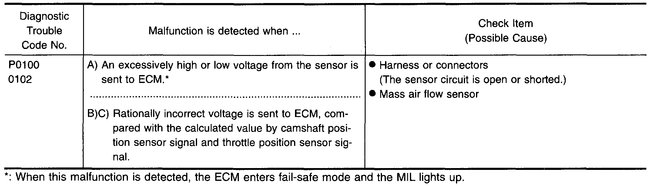
P0100
Vehicle ALL Diagnostic Trouble Codes ( DTC ) Testing and Inspection P Code Charts P0100
P0100
pic 1
COMPONENT DESCRIPTION
The mass air flow sensor is placed in the stream of intake air. It measures the intake flow rate by measuring a part of the entire intake flow. It consists of a hot wire that is supplied with electric current from the ECM. The temperature of the hot wire is controlled by the ECM a certain amount. The heat generated by the hot wire is reduced as the intake air flows around it. The more air, the greater the heat loss.
Therefore, the ECM must supply more electric current to the hot wire as air flow increases. This maintains the temperature of the hot wire. The ECM detects the air flow by means of this current change.
pic 2
ECM TERMINALS AND REFERENCE VALUE
Specification data are reference values and are measured between each terminal and (43) (ECCS ground).
pic 3
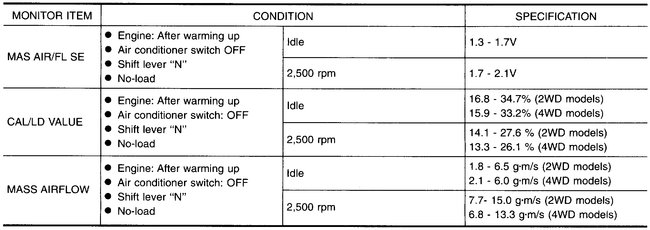
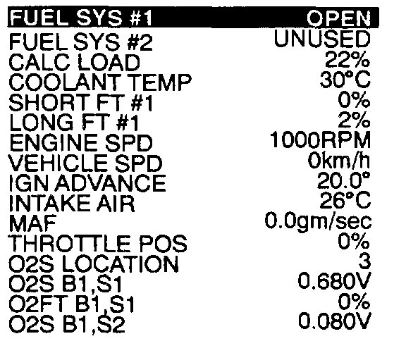
CONSULT REFERENCE VALUE IN DATA MONITOR MODE
Specification data are reference values.
pic 4
OPEN BOARD DIAGNOSIS LOGIC
Engine operating condition in fail-safe mode
Engine speed will not rise more than 2,400 rpm due to the fuel cut.
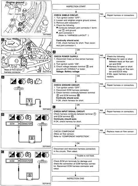
DIAGNOSTIC TROUBLE CODE CONFIRMATION PROCEDURE
Perform "Procedure for malfunction A" first. If the 1st trip DTC cannot be confirmed, perform "Procedure for malfunction B". If there is no problem on "Procedure for malfunction B", perform "Procedure for malfunction C", "OVERALL FUNCTION CHECK".
Procedure for Malfunction A
With CONSULT
(1)Turn ignition switch "ON" and wait at least 6 seconds.
pic 5
(2)Select "DATA MONITOR" mode with CONSULT.
(3)Start engine and wait at least 3 seconds.
OR
With GST
(1)Turn ignition switch "ON" and wait at least 6 seconds.
(2)Start engine and wait at least 3 seconds.
(3)Select "MODE 7" with GST.
OR
NO TOOLS
(1)Turn ignition switch "ON" and wait at least 6 seconds.
(2)Start engine and wait at least 3 seconds.
(3)Turn ignition switch "OFF", wait at least 7 seconds and then turn "ON".
(4)Perform "Diagnostic Test Mode II (Self-diagnostic results)" with ECM.
Procedure for Malfunction B
With CONSULT
(1)Turn ignition switch "ON".
pic 6
(2)Select "DATA MONITOR" mode with CONSULT.
(3)Start engine and warm it up sufficiently.
(4)Run engine for at least 10 seconds at idle speed.
OR
With GST
(1)Turn ignition switch "ON".
(2)Start engine and warm it up sufficiently.
(3)Run engine for at least 10 seconds at idle speed.
(4)Select "MODE 7" with GST.
OR
NO TOOLS
(1)Turn ignition switch "ON".
(2)Start engine and warm it up sufficiently.
(3)Run engine for at least 10 seconds at idle speed.
(4)Turn ignition switch "OFF", wait at least 7 seconds and then turn "ON".
(5)Perform "Diagnostic Test Mode II (Self-diagnostic results)" with ECM.
OVERALL FUNCTION CHECK
Use this procedure to check the overall function of mass air flow sensor. During this check a 1st trip DTC might not be confirmed.
Procedure for Malfunction C
With CONSULT
(1)Turn ignition switch "ON".
(2)Start engine and warm it up sufficiently.
(3)Select "DATA MONITOR" mode with CONSULT.
pic 7
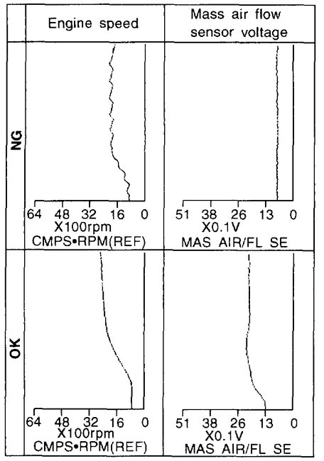
(4)Check the voltage of mass air flow sensor with "DATA MONITOR".
(5)Check for linear voltage rise in response to increases to about 4,000 rpm in engine speed.
OR
With GST
(1)Turn ignition switch "ON".
(2)Start engine and warm it up sufficiently.
pic 8
(3)Select "MODE 1" with GST.
(4)Check the mass air flow with "MODE 1".
(5)Check for linear mass air flow rise in response to increases to about 4,000 rpm in engine speed.
OR
NO TOOLS
(1)Turn ignition switch "ON".
(2)Start engine and warm it up sufficiently.
pic 9
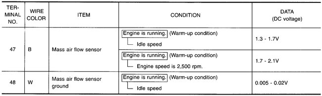
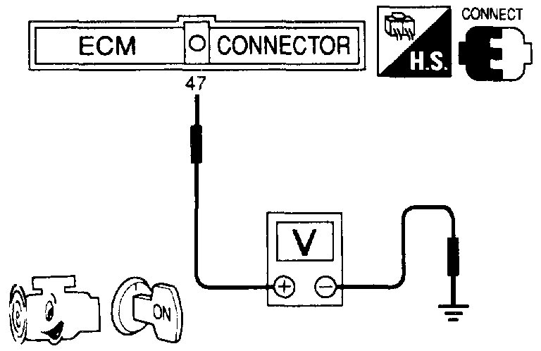
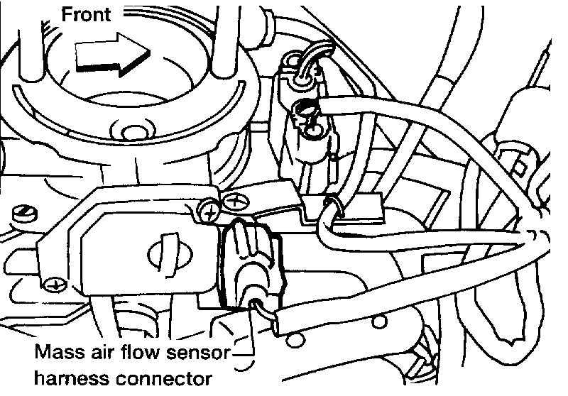
(3)Check the voltage between ECM terminal (47) and ground.
(4)Check for linear voltage rise in response to increases to about 4,000 rpm in engine speed.
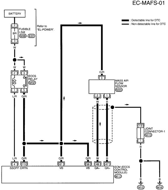
EC-MAFS-01 Mass Air Flow Sensor (MAFS) (DTC P0100)
Pic 10
WIRING DIAGRAM
pic 11
DIAGNOSTIC PROCEDURE
COMPONENT INSPECTION
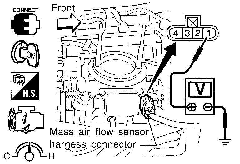
Mass Air Flow Sensor
1. Turn ignition switch "ON".
2. Start engine and warm it up sufficiently.
pic 12
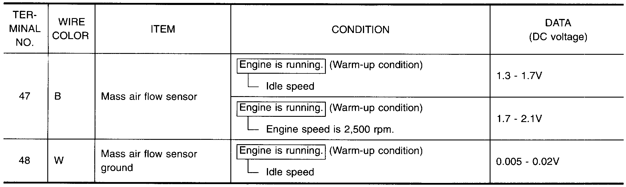
3. Check voltage between terminal 1 and ground.
Conditions / Voltage, V
Ignition switch "ON" (Engine stopped.) / Less than 1.0
Idle (Engine is warmed-up sufficiently.) / 1.3 - 1.7
2,500 rpm / 1.7 - 2.3
Idle to about 4,000 rpm / 1.3 - 1.7 to Approx. 4.0
*: Check for linear voltage rise in response to increases to about 4,000 rpm in engine speed.
pic 13
4. If NG, remove mass air flow sensor from air duct. Check hot wire for damage or dust.
____________________________________________________________________________________
1997 Nissan-Datsun Truck D21 Hardbody XE 2WD L4-2389cc 2.4L SOHC MFI (KA24E)
P0120
Vehicle ALL Diagnostic Trouble Codes ( DTC ) Testing and Inspection P Code Charts P0120
P0120
pic 14
pic 15
COMPONENT DESCRIPTION
The throttle position sensor responds to the accelerator pedal movement. This sensor is a kind of potentiometer which transforms the throttle position into output voltage and emits the voltage signal to the ECM. In addition, the sensor detects the opening and closing speed of the throttle valve and feeds the voltage signal to the ECM.
Idle position of the throttle valve is determined by the ECM receiving the signal from the throttle position sensor. This controls engine operation such as fuel cut. The throttle position sensor unit contains a built-in "Wide open and closed throttle position switch".
pic 16
ECM TERMINALS AND REFERENCE VALUE
Specification data are reference values and are measured between each terminal and (43) (ECCS ground).
pic 17
CONSULT REFERENCE VALUE IN DATA MONITOR MODE
Specification data are reference values
pic 18
ON BOARD DIAGNOSIS LOGIC
Engine operating condition in fail-safe mode
Throttle position will be determined based on the injected fuel amount and the engine speed.
Therefore, acceleration will be poor.
Condition / Driving Condition
When Engine is Idling / Normal
When accelerating / Poor accelerating
OVERALL FUNCTION CHECK
Use this procedure to check the overall function of the throttle position sensor circuit. During this check, a 1st trip DTC might not be confirmed.
With CONSULT
(1)Start engine and warm it up sufficiently.
(2)Turn ignition switch "OFF" and wait at least 7 seconds.
(3)Turn ignition switch "ON".
pic 19
(4)Select "MANU TRIG" and "HI SPEED" in "DATA MONITOR" mode with CONSULT
(5)Select "THRTL POS SEN" and "AE3SOL TH.P/S" in "DATA MONITOR" mode with CONSULT.
(6)Press RECORD on CONSULT SCREEN at the same time accelerator pedal is depressed.
pic 20
(7)Print out the recorded data and check the following:
- The voltage when accelerator pedal fully released is 0.3 - 0.7V.
- The voltage rise is linear in response to accelerator pedal depression.
- The voltage when accelerator pedal fully depressed is approximately 4V.
OR
Without CONSULT
(1)Start engine and warm it up sufficiently.
(2)Turn ignition switch "OFF" and wait at least 7 seconds.
(3)Turn ignition switch "ON".
pic 21
(4)Check the voltage between ECM terminal (23) and (43) (ground) and check the following:
- The voltage when accelerator pedal fully released is 0.3 - 0.7V.
- The voltage rise is linear in response to accelerator pedal depression.
- The voltage when accelerator pedal fully depressed is approximately 4V.
EC-TPS-01 Throttle Position (DTC P0120)
pic 22
WIRING DIAGRAM
pic 23
pic 24
DIAGNOSTIC PROCEDURE
COMPONENT INSPECTION
Throttle Position Sensor
1. Start engine and warm it up sufficiently.
2. Turn ignition switch "OFF".
3. Disconnect throttle position sensor harness connector.
pic 25
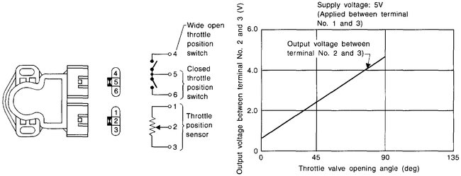
4. Check resistance between terminals 2 and 3 while opening throttle valve manually.
Throttle Valve conditions / Resistance at 25°C(77°F)
Completely closed / Approximately 0.5 k Ohms
Partially open / 0.5 - 0.4 K Ohms
Completely open / Approximately 4.0 K Ohms
If NG, replace throttle position sensor.
To adjust throttle position sensor, perform "BASIC INSPECTION".
____________________________
I hope something here helps.
Joe
__________________
I don't know if you want it but here are the diagnostics for the codes.
___________________
1997 Nissan-Datsun Truck D21 Hardbody XE 2WD L4-2389cc 2.4L SOHC MFI (KA24E)
P0100
Vehicle ALL Diagnostic Trouble Codes ( DTC ) Testing and Inspection P Code Charts P0100
P0100
pic 1
COMPONENT DESCRIPTION
The mass air flow sensor is placed in the stream of intake air. It measures the intake flow rate by measuring a part of the entire intake flow. It consists of a hot wire that is supplied with electric current from the ECM. The temperature of the hot wire is controlled by the ECM a certain amount. The heat generated by the hot wire is reduced as the intake air flows around it. The more air, the greater the heat loss.
Therefore, the ECM must supply more electric current to the hot wire as air flow increases. This maintains the temperature of the hot wire. The ECM detects the air flow by means of this current change.
pic 2
ECM TERMINALS AND REFERENCE VALUE
Specification data are reference values and are measured between each terminal and (43) (ECCS ground).
pic 3
CONSULT REFERENCE VALUE IN DATA MONITOR MODE
Specification data are reference values.
pic 4
OPEN BOARD DIAGNOSIS LOGIC
Engine operating condition in fail-safe mode
Engine speed will not rise more than 2,400 rpm due to the fuel cut.
DIAGNOSTIC TROUBLE CODE CONFIRMATION PROCEDURE
Perform "Procedure for malfunction A" first. If the 1st trip DTC cannot be confirmed, perform "Procedure for malfunction B". If there is no problem on "Procedure for malfunction B", perform "Procedure for malfunction C", "OVERALL FUNCTION CHECK".
Procedure for Malfunction A
With CONSULT
(1)Turn ignition switch "ON" and wait at least 6 seconds.
pic 5
(2)Select "DATA MONITOR" mode with CONSULT.
(3)Start engine and wait at least 3 seconds.
OR
With GST
(1)Turn ignition switch "ON" and wait at least 6 seconds.
(2)Start engine and wait at least 3 seconds.
(3)Select "MODE 7" with GST.
OR
NO TOOLS
(1)Turn ignition switch "ON" and wait at least 6 seconds.
(2)Start engine and wait at least 3 seconds.
(3)Turn ignition switch "OFF", wait at least 7 seconds and then turn "ON".
(4)Perform "Diagnostic Test Mode II (Self-diagnostic results)" with ECM.
Procedure for Malfunction B
With CONSULT
(1)Turn ignition switch "ON".
pic 6
(2)Select "DATA MONITOR" mode with CONSULT.
(3)Start engine and warm it up sufficiently.
(4)Run engine for at least 10 seconds at idle speed.
OR
With GST
(1)Turn ignition switch "ON".
(2)Start engine and warm it up sufficiently.
(3)Run engine for at least 10 seconds at idle speed.
(4)Select "MODE 7" with GST.
OR
NO TOOLS
(1)Turn ignition switch "ON".
(2)Start engine and warm it up sufficiently.
(3)Run engine for at least 10 seconds at idle speed.
(4)Turn ignition switch "OFF", wait at least 7 seconds and then turn "ON".
(5)Perform "Diagnostic Test Mode II (Self-diagnostic results)" with ECM.
OVERALL FUNCTION CHECK
Use this procedure to check the overall function of mass air flow sensor. During this check a 1st trip DTC might not be confirmed.
Procedure for Malfunction C
With CONSULT
(1)Turn ignition switch "ON".
(2)Start engine and warm it up sufficiently.
(3)Select "DATA MONITOR" mode with CONSULT.
pic 7
(4)Check the voltage of mass air flow sensor with "DATA MONITOR".
(5)Check for linear voltage rise in response to increases to about 4,000 rpm in engine speed.
OR
With GST
(1)Turn ignition switch "ON".
(2)Start engine and warm it up sufficiently.
pic 8
(3)Select "MODE 1" with GST.
(4)Check the mass air flow with "MODE 1".
(5)Check for linear mass air flow rise in response to increases to about 4,000 rpm in engine speed.
OR
NO TOOLS
(1)Turn ignition switch "ON".
(2)Start engine and warm it up sufficiently.
pic 9
(3)Check the voltage between ECM terminal (47) and ground.
(4)Check for linear voltage rise in response to increases to about 4,000 rpm in engine speed.
EC-MAFS-01 Mass Air Flow Sensor (MAFS) (DTC P0100)
Pic 10
WIRING DIAGRAM
pic 11
DIAGNOSTIC PROCEDURE
COMPONENT INSPECTION
Mass Air Flow Sensor
1. Turn ignition switch "ON".
2. Start engine and warm it up sufficiently.
pic 12
3. Check voltage between terminal 1 and ground.
Conditions / Voltage, V
Ignition switch "ON" (Engine stopped.) / Less than 1.0
Idle (Engine is warmed-up sufficiently.) / 1.3 - 1.7
2,500 rpm / 1.7 - 2.3
Idle to about 4,000 rpm / 1.3 - 1.7 to Approx. 4.0
*: Check for linear voltage rise in response to increases to about 4,000 rpm in engine speed.
pic 13
4. If NG, remove mass air flow sensor from air duct. Check hot wire for damage or dust.
____________________________________________________________________________________
1997 Nissan-Datsun Truck D21 Hardbody XE 2WD L4-2389cc 2.4L SOHC MFI (KA24E)
P0120
Vehicle ALL Diagnostic Trouble Codes ( DTC ) Testing and Inspection P Code Charts P0120
P0120
pic 14
pic 15
COMPONENT DESCRIPTION
The throttle position sensor responds to the accelerator pedal movement. This sensor is a kind of potentiometer which transforms the throttle position into output voltage and emits the voltage signal to the ECM. In addition, the sensor detects the opening and closing speed of the throttle valve and feeds the voltage signal to the ECM.
Idle position of the throttle valve is determined by the ECM receiving the signal from the throttle position sensor. This controls engine operation such as fuel cut. The throttle position sensor unit contains a built-in "Wide open and closed throttle position switch".
pic 16
ECM TERMINALS AND REFERENCE VALUE
Specification data are reference values and are measured between each terminal and (43) (ECCS ground).
pic 17
CONSULT REFERENCE VALUE IN DATA MONITOR MODE
Specification data are reference values
pic 18
ON BOARD DIAGNOSIS LOGIC
Engine operating condition in fail-safe mode
Throttle position will be determined based on the injected fuel amount and the engine speed.
Therefore, acceleration will be poor.
Condition / Driving Condition
When Engine is Idling / Normal
When accelerating / Poor accelerating
OVERALL FUNCTION CHECK
Use this procedure to check the overall function of the throttle position sensor circuit. During this check, a 1st trip DTC might not be confirmed.
With CONSULT
(1)Start engine and warm it up sufficiently.
(2)Turn ignition switch "OFF" and wait at least 7 seconds.
(3)Turn ignition switch "ON".
pic 19
(4)Select "MANU TRIG" and "HI SPEED" in "DATA MONITOR" mode with CONSULT
(5)Select "THRTL POS SEN" and "AE3SOL TH.P/S" in "DATA MONITOR" mode with CONSULT.
(6)Press RECORD on CONSULT SCREEN at the same time accelerator pedal is depressed.
pic 20
(7)Print out the recorded data and check the following:
- The voltage when accelerator pedal fully released is 0.3 - 0.7V.
- The voltage rise is linear in response to accelerator pedal depression.
- The voltage when accelerator pedal fully depressed is approximately 4V.
OR
Without CONSULT
(1)Start engine and warm it up sufficiently.
(2)Turn ignition switch "OFF" and wait at least 7 seconds.
(3)Turn ignition switch "ON".
pic 21
(4)Check the voltage between ECM terminal (23) and (43) (ground) and check the following:
- The voltage when accelerator pedal fully released is 0.3 - 0.7V.
- The voltage rise is linear in response to accelerator pedal depression.
- The voltage when accelerator pedal fully depressed is approximately 4V.
EC-TPS-01 Throttle Position (DTC P0120)
pic 22
WIRING DIAGRAM
pic 23
pic 24
DIAGNOSTIC PROCEDURE
COMPONENT INSPECTION
Throttle Position Sensor
1. Start engine and warm it up sufficiently.
2. Turn ignition switch "OFF".
3. Disconnect throttle position sensor harness connector.
pic 25
4. Check resistance between terminals 2 and 3 while opening throttle valve manually.
Throttle Valve conditions / Resistance at 25°C(77°F)
Completely closed / Approximately 0.5 k Ohms
Partially open / 0.5 - 0.4 K Ohms
Completely open / Approximately 4.0 K Ohms
If NG, replace throttle position sensor.
To adjust throttle position sensor, perform "BASIC INSPECTION".
____________________________
I hope something here helps.
Joe
Images (Click to enlarge)


Mar 1, 2020 at 7:41 PM
Joe, I received the MAF early today. I removed the original one and wasn't paying attention to the way the MAF looked after it came out of the throttle body (the part that goes in throttle body). so I take the new one and it will not fit into the throttle body so I'm thinking they sent me one for another year than my truck. My original didn't look right where that part goes into the T. Body so I took my flashlight and looked into T. Body through a small hole and seen a plastic piece still in there, the tip was lodged and had stayed in there. This plastic piece slips over the sensor. I Took a screwdriver and pushed it out, now the new sensor is in and working as of now, will let you know more when I drive the truck tonight.
Mar 2, 2020 at 2:49 PM
The truck is running good but I'll probably get a TPS for later on in case I need it.
Mar 4, 2020 at 8:29 PM
Joe, thanks for all your help.
Mar 5, 2020 at 7:33 PM
You are very welcome. I'm glad to hear it is running good for you.
Take care of yourself.
Joe
Take care of yourself.
Joe
Mar 5, 2020 at 8:27 PM
Joe , it's got a little miss when it is warming up when I get to a certain speed but I think that could be that TPS and I have one on the way, should be here in a couple days in the mean time had to replace my passenger caliper on drivers side, seals leaking brake fluid . It's running is all that counts, has a great motor in it, only 178,000 miles .
Mar 6, 2020 at 12:48 PM
Caliper was on passenger side, miss stated that up above, sorry.
Mar 6, 2020 at 12:51 PM
Joe the mathematical formula for changing lbs/minute to grans per second is we take the lbs/minute x 117 and that gives us the grains/s.
Mar 18, 2020 at 3:30 PM

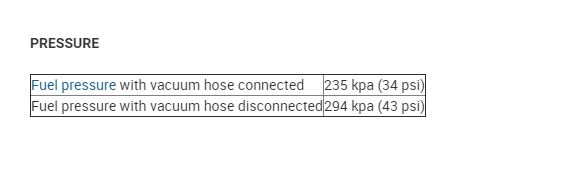
Just to add to your conversation with Joe, the fuel pressure is within specs.
Roy
Roy
Image (Click to enlarge)
Mar 19, 2020 at 5:19 AM