A/C compressor will not come on unless relay is jumped

2008 CHEVROLET UPLANDER
247,000 MILES • 3.9L • V6 • 2WD • AUTOMATIC
Avatar
JASON123177
  • MEMBER
  • 27 POSTS
I changed the front and rear expansion valves. When I went to recharge the system, after pulling and making sure the system held a vacuum of 30in/hg of course, it would not take a full can of refrigerant. I discovered that the compressor clutch wasn’t engaging. I know I’m not supposed to do this, but I jumped pins 30 and 87 on the clutch relay, and the compressor ran and sucked in refrigerant like there was no tomorrow. After putting the recommended 2.2lbs of R134a, I was getting readings of 205 psi on the high side and 48-50 on the low side but, the clutch still would not engage unless the relay was jumped. This led me to believe that either the control module or pressure transducer was bad. I got a control module out of a wrecked vehicle instead of forking out over $400.00 on a new one. Installed it, reset the PCM and tried the A/C again. Nothing changed at all. I installed a new pressure transducer yesterday, reset the PCM, and again, nothing changed. I did notice that there is a connector in between the condenser coil and grill that isn’t connected to anything. Could this be for an ambient temperature sensor, and could that be the cause of the compressor clutch not engaging? If not, what in the world is going on, because I am baffled at this point.
Jul 19, 2019 at 5:09 AM
Advertisement
Avatar
ASEMASTER6371
  • CERTIFIED EXPERT
  • 52,796 POSTS
Good morning,

First, no need to reset PCM. If your repair was correct, it will come on by itself.

Did you verify power to the control side of the relay? I will attach a wiring diagram for you to view.

Also, the low side is way too high. It should be 25-30 lbs. Did you change the accumulator as well?

Roy
Jul 19, 2019 at 6:40 AM
Avatar
JASON123177
  • MEMBER
  • 27 POSTS
Good morning to you as well. Thank you for your prompt reply. I did not check to see if there was power to the relay. Never dawned on me. I did switch it out with two other relays that were exactly the same (horn and fuel pump) just to make sure the relay was good. Also, I did not change the accumulator either. What would cause the low side to be too high? The ambient temperature was about 94 degrees F when I last got pressure readings.
Jul 19, 2019 at 6:51 AM
Advertisement
Avatar
ASEMASTER6371
  • CERTIFIED EXPERT
  • 52,796 POSTS
The accumulator is required once the system is opened.

Check the power at the relay and let me know what you find.

Roy
Jul 19, 2019 at 6:52 AM
Avatar
JASON123177
  • MEMBER
  • 27 POSTS
I will check it when I get home this afternoon and let you know. The accumulator is mounted on the drivers side of the condenser coil correct?
Jul 19, 2019 at 6:54 AM
Avatar
ASEMASTER6371
  • CERTIFIED EXPERT
  • 52,796 POSTS
Nope, looks like it is on the condenser for your truck.

Picture attached.

Roy
Jul 19, 2019 at 1:20 PM
Avatar
JASON123177
  • MEMBER
  • 27 POSTS
Yes, that is where I was talking about.
Jul 19, 2019 at 2:43 PM
Avatar
ASEMASTER6371
  • CERTIFIED EXPERT
  • 52,796 POSTS
Yep, be careful removing it. It is common for the bolts to seize when releasing the dryer.

Roy
Jul 19, 2019 at 2:46 PM
Avatar
JASON123177
  • MEMBER
  • 27 POSTS
I have 13vdc at pin 86 and nothing at pin 85.
Jul 19, 2019 at 2:57 PM
Avatar
ASEMASTER6371
  • CERTIFIED EXPERT
  • 52,796 POSTS
What about 30? Do you have the power there?

85 is the ground to the PCM. It will ground the control side when it sees the correct signals from the pressure switches.

Roy
Jul 19, 2019 at 3:02 PM
Avatar
JASON123177
  • MEMBER
  • 27 POSTS
Pin 30 is 0 pin 87 is 13vdc.
Jul 19, 2019 at 3:04 PM
Avatar
ASEMASTER6371
  • CERTIFIED EXPERT
  • 52,796 POSTS
That's your problem. You should have power at 30 all the time.

check the wiring diagram I posted in the beginning. Check the AC clutch fuse for power on both sides with a test light or voltmeter.

Roy
Jul 19, 2019 at 3:11 PM
Avatar
JASON123177
  • MEMBER
  • 27 POSTS
There isn’t power on either side of the clutch fuse.
Jul 19, 2019 at 3:14 PM
Avatar
JASON123177
  • MEMBER
  • 27 POSTS
I am going to post a video of me checking the pins. Something weird is going on.
Jul 19, 2019 at 3:22 PM
Avatar
ASEMASTER6371
  • CERTIFIED EXPERT
  • 52,796 POSTS
Okay, if there is no power to the fuse, the fuse box is the failure. It is common for failed fuses boxes with GM.

Roy
Jul 19, 2019 at 3:28 PM
Avatar
JASON123177
  • MEMBER
  • 27 POSTS
When I connect to the battery ground, it does show power on both sides of the fuse. But, when I ground to the ground on the side of the fuse box it shows no power to either side of the fuse. The video is of me testing the relay plug off of the battery ground and the ground on the side of the fuse box.
Jul 19, 2019 at 3:37 PM
Avatar
ASEMASTER6371
  • CERTIFIED EXPERT
  • 52,796 POSTS
You need to put the black wire to the battery ground. Then test for voltage to the fuse with the fuse installed. You need power on both sides.

If you have power, then you have a wiring issue from the fuse to the relay terminal 30.

Roy
Jul 19, 2019 at 3:41 PM
Avatar
JASON123177
  • MEMBER
  • 27 POSTS
Were you able to watch the video of me testing the relay plug?
Jul 19, 2019 at 3:42 PM
Avatar
ASEMASTER6371
  • CERTIFIED EXPERT
  • 52,796 POSTS
Yes but it looked like the fuse was out.

Roy
Jul 19, 2019 at 3:44 PM
Avatar
JASON123177
  • MEMBER
  • 27 POSTS
The clutch fuse was in. The relay was out.
Jul 19, 2019 at 3:45 PM
Avatar
JASON123177
  • MEMBER
  • 27 POSTS
Will it be possible for me to email you my phone number and have you to call me? It may be easier to go through this on the phone.
Jul 19, 2019 at 3:47 PM
Avatar
JASON123177
  • MEMBER
  • 27 POSTS
I really appreciate you sharing your time and knowledge with me!!
Jul 19, 2019 at 3:48 PM
Avatar
ASEMASTER6371
  • CERTIFIED EXPERT
  • 52,796 POSTS
No, this is the only forum that we are allowed to use.

Roy
Jul 19, 2019 at 3:50 PM
Avatar
JASON123177
  • MEMBER
  • 27 POSTS
Okay. That’s fine. So, with the engine running and A/C on, pins 85 and 30 have power. Pins 86 and 87 do not.
Jul 19, 2019 at 3:57 PM
Avatar
ASEMASTER6371
  • CERTIFIED EXPERT
  • 52,796 POSTS
They will not. 87 goes to the clutch when the relay energizes.

86 is a ground to the PCM. It will ground the relay when it sees the correct signal from the switches.

Do you have a scan tool to view the A/C system and see if the signals from the switches are getting to the PCM?

Roy
Jul 19, 2019 at 4:08 PM
Avatar
JASON123177
  • MEMBER
  • 27 POSTS
No I do not, but I can borrow one Monday more than likely.
Jul 19, 2019 at 4:17 PM
Avatar
ASEMASTER6371
  • CERTIFIED EXPERT
  • 52,796 POSTS
Okay, keep me updated.

Roy
Jul 19, 2019 at 4:20 PM
Avatar
JASON123177
  • MEMBER
  • 27 POSTS
Would the ambient air temperature sensor have anything to do with it? The reason I ask is there is a plug in between the condenser and grill that isn’t hooked up to anything and I suspect that is where the ambient temperature sensor belongs. I don’t know if the air worked last summer because we just got the van last November.
Jul 19, 2019 at 4:21 PM
Avatar
JASON123177
  • MEMBER
  • 27 POSTS
I will for sure. Thank you again for your help!
Jul 19, 2019 at 4:21 PM
Avatar
ASEMASTER6371
  • CERTIFIED EXPERT
  • 52,796 POSTS
You are welcome.

Always glad to help.

Roy
Jul 19, 2019 at 4:45 PM
Avatar
JASON123177
  • MEMBER
  • 27 POSTS
Roy,
I was finally able to get the scanner put on the van and the fault code for the A/C is p0645.
Jul 24, 2019 at 3:24 PM
Avatar
ASEMASTER6371
  • CERTIFIED EXPERT
  • 52,796 POSTS
OK, 645 is for the clutch relay or a bad PCM.

Roy


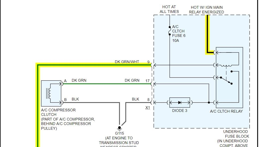
Circuit/System Description

Ignition voltage is supplied directly to the A/C compressor clutch relay. The engine control module ECM controls the relay by grounding the A/C clutch relay control circuit via an internal solid state device called a driver. The primary function of the driver is to supply the ground for the component being controlled. The driver has a fault line which is monitored by the ECM. When the ECM is commanding a component ON, the voltage of the control circuit should be near 0 volts. When the ECM is commanding the control circuit to a component OFF, the voltage potential of the circuit should be near battery voltage.

Conditions for Running the DTC

* The ignition voltage is between 9 and 18 volts.
* The engine speed is more than 80 RPM.
* The ECM A/C Compressor Clutch Relay Control transitions between ON to OFF or from OFF to ON.

Conditions for Setting the DTC

* A short to ground on the A/C compressor clutch relay control circuit
* A short to voltage on the A/C compressor clutch relay control circuit
* An open circuit on the A/C compressor clutch relay control circuit or relay
* An internally shorted or excessively low resistance A/C clutch relay coil

Action Taken When the DTC Sets

* The A/C clutch relay is commanded OFF.
* The conditions for which the DTC was set will be stored in the Failure Records data only. No information will be stored as Freeze Frame data.

Conditions for Clearing the DTC

The history DTC will clear after 40 fault-free ignition cycles.

Reference Information
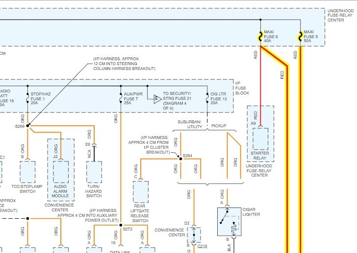
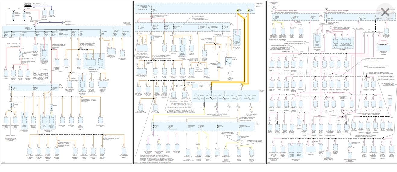
Schematic Reference

HVAC Schematics (See: Heating and Air Conditioning > Electrical > HVAC Schematics)
Connector End View Reference

Component Connector End Views (See: Vehicle > Connector Views)
Description and Operation

* Air Temperature Description and Operation (See: Heating and Air Conditioning > Components > Air Temperature Description and Operation)
* Air Delivery Description and Operation (See: Heating and Air Conditioning > Components Air Delivery Description and Operation)

Electrical Information Reference

* Circuit Testing (See: Vehicle > Component Tests and General Diagnostics)
* Connector Repairs (See: Vehicle > Component Tests and General Diagnostics)
* Testing for Intermittent Conditions and Poor Connections (See: Vehicle > Component Tests and General Diagnostics)
* Wiring Repairs (See: Vehicle > Component Tests and General Diagnostics)

Scan Tool Reference

Control Module References (See: Vehicle > Programming and Relearning) for Scan Tool Information

Circuit/System Verification

Ignition ON, command the A/C relay ON and OFF with a scan tool. Observe the A/C compressor operation, the A/C compressor clutch should engage and disengage when changing between the commanded states.

Circuit/System Testing

1. Ignition OFF, disconnect the A/C CLTCH relay.
2. Ignition ON, verify that a test lamp does not illuminate between the relay coil control circuit terminal and ground.

If the test lamp illuminates, test the control circuit for a short to voltage.

3. Verify that a test lamp illuminates between the relay coil B+ circuit terminal and ground.

If the test lamp does not illuminate, Refer to DTC B1428 (See: A L L Diagnostic Trouble Codes ( DTC ) > B Code Charts > B1428).

4. Connect a test lamp between the relay coil B+ circuit terminal and the relay coil control circuit terminal.
5. Command the A/C relay ON and OFF with a scan tool. The test lamp should turn ON and OFF when changing between the commanded states.

If the test lamp is always ON, test the control circuit for a short to ground. If the circuit tests normal, ECM.
If the test lamp is always OFF, test the control circuit for a short to voltage, or an open/high resistance. If the circuit tests normal, replace the ECM.

6. If all circuits test normal, test or replace the A/C CLTCH relay.

Component Testing

1. Ignition OFF, disconnect the A/C CLTCH relay.
2. Test for 60-180 ohms of resistance between terminals 85 and 86.

If the resistance is not within the specified range, replace the relay.

3. Test for infinite resistance between the following terminals:

* 30 and 86
* 30 and 87
* 30 and 85
* 85 and 87

If not the specified value, replace the relay.

4. Install a 30-amp fused jumper wire between relay terminal 85 and 12 volts. Install a jumper wire between relay terminal 86 and ground. Test for less than 2 ohms of resistance between terminals 30 and 87.

If greater than the specified range, replace the relay.

Repair Instructions

Perform the Diagnostic Repair Verification (See: A L L Diagnostic Trouble Codes ( DTC ) > Verification Tests) after completing the diagnostic procedure.

* Relay Replacement (Attached to Wire Harness) (See: Power Distribution Relay > Removal and Replacement > Relay Replacement (Attached to Wire Harness))Relay Replacement (Within an Electrical Center) (See: Power Distribution Relay > Removal and Replacement > Relay Replacement (Within an Electrical Center))
* Control Module References (See: Vehicle > Programming and Relearning) for ECM replacement, setup, and programming
Jul 25, 2019 at 5:23 AM
Avatar
JASON123177
  • MEMBER
  • 27 POSTS
Thank you very much. That is some very useful information and hopefully it will help me solve the issue!
Jul 25, 2019 at 7:08 AM
Avatar
ASEMASTER6371
  • CERTIFIED EXPERT
  • 52,796 POSTS
You are welcome.

Keep me updated.

Roy
Jul 25, 2019 at 7:22 AM
Avatar
JASON123177
  • MEMBER
  • 27 POSTS
In step 5 of circuit/system testing, there is always voltage between terminal 30 and 87. So, how do I find where the short is?
Jul 25, 2019 at 5:14 PM
Avatar
ASEMASTER6371
  • CERTIFIED EXPERT
  • 52,796 POSTS
30 is battery powered. 87 goes to the load.

Roy
Jul 25, 2019 at 5:38 PM
Avatar
JASON123177
  • MEMBER
  • 27 POSTS
Ok, I know that I have been a bit confusing because I didn’t really know what I was doing when it came to testing the electrical part of this system. But, I think I have figured it out after doing some studying. So, terminal 30 always has 14.2vdc when key is on. Terminal 86 has 14.2vdc when there is demand for A/C and 0vdc when there is not. I am thinking that those voltages are what they’re supposed to be. So, there is an issue between terminal 85 and the pcm. The pcm isn’t allowing the circuit to be complete between terminals 85 and 86 for some reason and not allowing the switch to close between pins 30 and 87 in the relay. Therefore the pcm isn’t providing the ground to complete the circuit between terminals 85 and 86. The circuit from the compressor to terminal 87 has to be complete because the compressor runs when 30 is jumped over to 87. This is where the pressure transducer comes in to play correct? But, the pressures should be within operating range at 210psi on the high side and 50 psi on the low side. If there was a condition where something grounded out between terminal 85 and the pcm, electricity would still flow between pins 85 and 86 and cause the relay to close and the compressor clutch to engage. So, I am thinking that there is definitely a problem with the pcm. Please correct me if I am wrong.
Jul 25, 2019 at 7:47 PM
Avatar
ASEMASTER6371
  • CERTIFIED EXPERT
  • 52,796 POSTS
Correct. The PCM grounds the control side of the relay to power pin 87. It will do that when it sees the correct signal from the pressure switches.

Even when it does turn it on, the low side is incorrect. It is too high as I stated before.

Roy
Jul 26, 2019 at 4:29 AM
Avatar
ASEMASTER6371
  • CERTIFIED EXPERT
  • 52,796 POSTS
They come from maxi fuses. The actual fuse block may be the issue.

Roy
Jul 26, 2019 at 4:33 AM
Avatar
JASON123177
  • MEMBER
  • 27 POSTS
So, is my next step to try and get the low pressure down? If so, what is the best way to do that? To my knowledge, high readings on the low pressure side indicate either a low refrigerant level, or air and moisture in the system, which in this case would indicate a leak because I thoroughly vacuumed the system before charging it. At what pressure should the pressure transducer send the correct signal to operate the compressor? Or should I be tracing down electrical issues? I feel like I am going to be a full blown master mechanic by the time we get this A/C working correctly. Lol
Jul 26, 2019 at 5:14 AM
Avatar
JASON123177
  • MEMBER
  • 27 POSTS
If I should be tracing down electrical issues, how would I test the fuse block. Also, the scan tool would not operate the A/C. It kept saying something to the effect of not being able to connect to the A/C system. But, it read the engine DTC’s
Jul 26, 2019 at 5:16 AM