Jan 26, 2011 at 11:58 AM
Lack of Acceleration
2006 FORD E-SERIES VAN
Advertisement
Thanks \a lot.just as i told you that i am on the process of changing the throttle body for my ford E-150 van,someone told me that if i should change it i will have to reprogramme the PCM.Please i want to know if this is true.Again is the TPS a major factor or the APPS

There is no neccessity to reprogram the PCM when the TPS is replaced.
Both are different components of the system and they cannot do without each other so how to identify which is major?
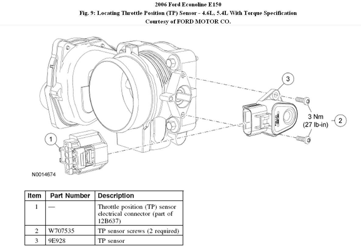
THROTTLE POSITION (TP) SENSOR - 4.6L, 5.4L
Removal
1. Remove the engine cover.
NOTE:
The clip must be pulled out before disconnecting the electrical connector.
2. Disconnect the throttle position (TP) sensor electrical connector.
CAUTION:Failure to remove the TP sensor screws in the following manner will result in damage to the screws. First loosen the screws 1-2 full turns using a hand tool and then use a suitable high speed driver to complete the removal.
3. Remove and discard the 2 screws and the TP sensor.
Installation
CAUTION:Do not reuse the TP sensor and screws. A new TP sensor and screws must be installed.
CAUTION:Do not use a high speed driver to install the new screws or damage to the TP sensor can occur.
NOTE:
When installing the new TP sensor, make sure that the radial locator tab on the TP sensor is aligned with the radial locator hole on the throttle body.
1. Position the new TP sensor and install the 2 new screws.
• Tighten to 3 Nm (27 lb-in).
2. Connect the TP sensor electrical connector.
3. Install the engine cover.
© 2008 Mitchell Repair Information Co., LLC.
Both are different components of the system and they cannot do without each other so how to identify which is major?
THROTTLE POSITION (TP) SENSOR - 4.6L, 5.4L
Removal
1. Remove the engine cover.
NOTE:
The clip must be pulled out before disconnecting the electrical connector.
2. Disconnect the throttle position (TP) sensor electrical connector.
CAUTION:Failure to remove the TP sensor screws in the following manner will result in damage to the screws. First loosen the screws 1-2 full turns using a hand tool and then use a suitable high speed driver to complete the removal.
3. Remove and discard the 2 screws and the TP sensor.
Installation
CAUTION:Do not reuse the TP sensor and screws. A new TP sensor and screws must be installed.
CAUTION:Do not use a high speed driver to install the new screws or damage to the TP sensor can occur.
NOTE:
When installing the new TP sensor, make sure that the radial locator tab on the TP sensor is aligned with the radial locator hole on the throttle body.
1. Position the new TP sensor and install the 2 new screws.
• Tighten to 3 Nm (27 lb-in).
2. Connect the TP sensor electrical connector.
3. Install the engine cover.
© 2008 Mitchell Repair Information Co., LLC.
Image (Click to enlarge)
Jan 26, 2011 at 1:29 PM
Advertisement
Thanks. But if i have to change the complete throttle body do i have to undergo this process
Jan 26, 2011 at 2:10 PM
No, then this process is not required.
Jan 26, 2011 at 6:39 PM
Hi,KHLow its been long time regarding the E-150 van.When i erazed the codes and retreived it back i kept on seeing the foll. codes: po193pend po223pend p2104pend p2110pend po451pend and po122mil.Another discovery is that whenever i press down the accelerator pedal,the engine wont start but if i release the pedal it will start immediately.Finally whenever i the switch that opens the throttle plate the vehicle stalls while idling but if i remove the switch it wont.Does it shows that the Accelerator pedal is working,does the Accelerator pedal has its own sensor?Please give me your expertise opinion to these findings.Thanks a lot
Feb 5, 2011 at 4:08 PM
There are 3 new codes.
P0122 is related to the TPS and P0193. P0223 is a fault with the TPS.
DD3 CONTINUOUS MEMORY DTC P0190, KOEO AND KOER DTCS P0192 AND P0193: CHECK FRP SENSOR FOR FUEL LEAKS
NOTE:
Repair any fuel pump DTCs prior to this test.
• Key ON, engine running.
• Idle the engine for 2 minutes.
• Inspect the FRP vacuum hose between the intake manifold and the FRP sensor for air leaks and correct connection.
• Key in OFF position.
• Remove the vacuum hose from the FRP.
• Inspect the FRP and vacuum hose for traces of fuel.
Is any fuel present?
Yes
INSTALL a new FRP sensor. GO to Pinpoint Test HC. CLEAR the DTCs. REPEAT the self-test.
No
GO to DD4.
DD4 CHECK THE VREF AND SIGRTN CIRCUITS FOR AN OPEN IN THE HARNESS
• Connect the vacuum hose to the FRP.
• FRP Sensor connector disconnected.
• Key ON, engine OFF.
• Measure the voltage between:
( + ) FRP Sensor Connector, Harness Side, VREF - Pin 1
( - ) FRP Sensor Connector, Harness Side, SIGRTN - Pin 2
Is the voltage between 4.5 - 5.5 V?
Yes
GO to DD7.
No
GO to Pinpoint Test C.
© 2008 Mitchell Repair Information Co., LLC.
The Accelerator and TPS are both related to the starting condition mentioned and either could be the cause of the non starting with the accelerator depressed or not.
Feb 6, 2011 at 6:23 PM
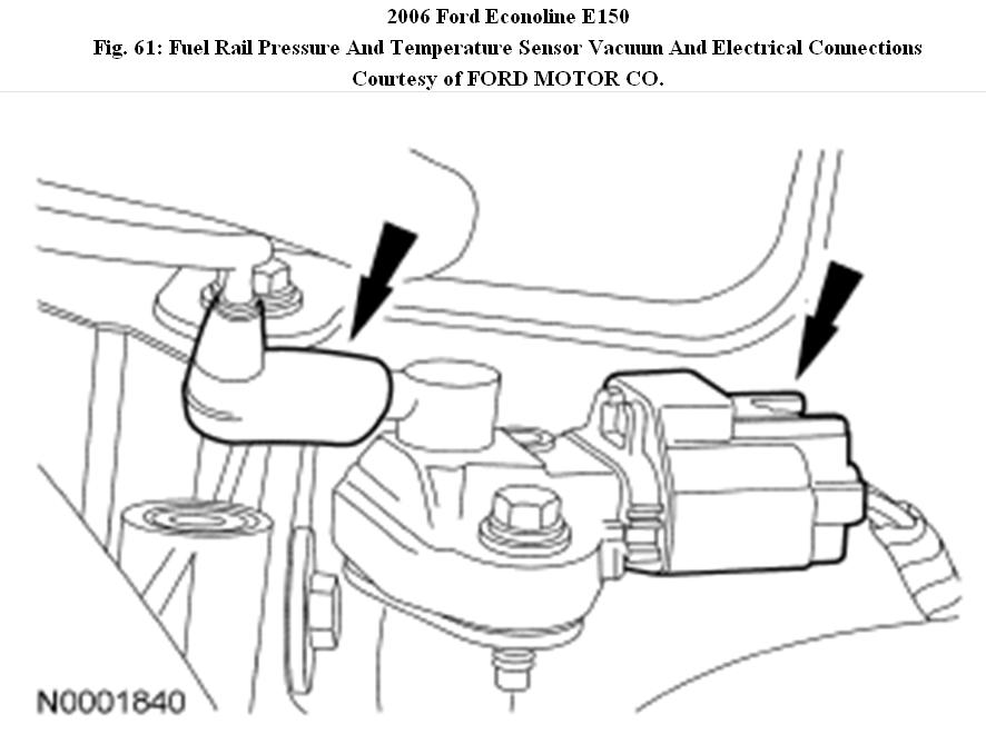
Thanks alot but you didnt say anything about the po451 and i forgot to include p2107.Again, what is FRP sensor and its vacuum horse or even the connector and where is it located
Feb 7, 2011 at 7:30 PM
P0451 is a fault with the EVAP system and can be triggerred by a loose fuel filler cap.
DTC P0451: CHECK THE FTP SENSOR FOR CORRECT OPERATION
• Key in OFF position.
• Remove the fuel filler cap.
• Key ON, engine OFF.
• Access the PCM and monitor the FTP PID.
Is the pressure between -0.42 and 0.42 kPa (-1.7 and 1.7 in-H2O)?
Yes
CHECK for kinks or bends in the fuel vapor hoses/tubes between the fuel tank and dust separator. CHECK the EVAP canister ports and canister vent hose assembly for contamination or debris. CHECK the dust separator for blockage. REPAIR as necessary.
No - INSTALL a new FTP sensor.
CLEAR the DTCs. REPEAT the self-test.
© 2008 Mitchell Repair Information Co., LLC.
P2107 is a fault with the TAC.
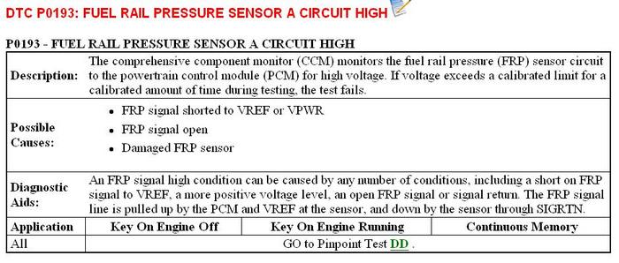
FRP = Fuel Rail Pressure, located on fuel rail.
DTC P0451: CHECK THE FTP SENSOR FOR CORRECT OPERATION
• Key in OFF position.
• Remove the fuel filler cap.
• Key ON, engine OFF.
• Access the PCM and monitor the FTP PID.
Is the pressure between -0.42 and 0.42 kPa (-1.7 and 1.7 in-H2O)?
Yes
CHECK for kinks or bends in the fuel vapor hoses/tubes between the fuel tank and dust separator. CHECK the EVAP canister ports and canister vent hose assembly for contamination or debris. CHECK the dust separator for blockage. REPAIR as necessary.
No - INSTALL a new FTP sensor.
CLEAR the DTCs. REPEAT the self-test.
© 2008 Mitchell Repair Information Co., LLC.
P2107 is a fault with the TAC.
FRP = Fuel Rail Pressure, located on fuel rail.
Images (Click to enlarge)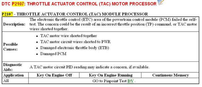

Feb 8, 2011 at 11:54 AM
Thanks a lot.What is fuel filler cap and FTP sensor and pls where is there location.Again somone said ford was having an issue with the connector under the dash that connects the accelerator position sensor to the main wiring harness,that it can be cleaned and reassembled but i dont know how true this is.Please can you explain this to me.
Feb 9, 2011 at 5:36 PM
Fuel filler cap is the cap where you put in gas.
FTP is Fuel Tnak Pressure sensor, located at fuel tank.
In my previous post I already told you to check connectors for contaminations or looseness. The wire connectors to the accelerator is the one mentioned.
FTP is Fuel Tnak Pressure sensor, located at fuel tank.
In my previous post I already told you to check connectors for contaminations or looseness. The wire connectors to the accelerator is the one mentioned.
Feb 10, 2011 at 12:33 PM
Thanks a lot.Please on the camry 98 model i talked about i saw the following codes;po304,po300,Po301 and Po105.It is a 4 plug engine.pls can you tell me what the problem is?
Feb 10, 2011 at 6:16 PM
DTC P0105: MANIFOLD ABSOLUTE PRESSURE (MAP)/BAROMETRIC PRESSURE SENSOR CIRCUIT
CAUTION: If ECM replacement is instructed in following testing, always ensure ECM connectors and ground circuit are okay. If either are suspect, repair and repeat testing to confirm ECM malfunction.
Circuit Description
MAP sensor detects manifold pressure as a voltage that is supplied to ECM. Signal is used to determine basic injection duration and basic injection advance angle. ECM will operate in fail-safe mode if DTC P0105 is set. DTC is set when ECM detects an open or short in MAP circuit.
Possible causes are:
• MAP open or short circuit.
• MAP sensor.
• ECM.
Diagnosis & Repair
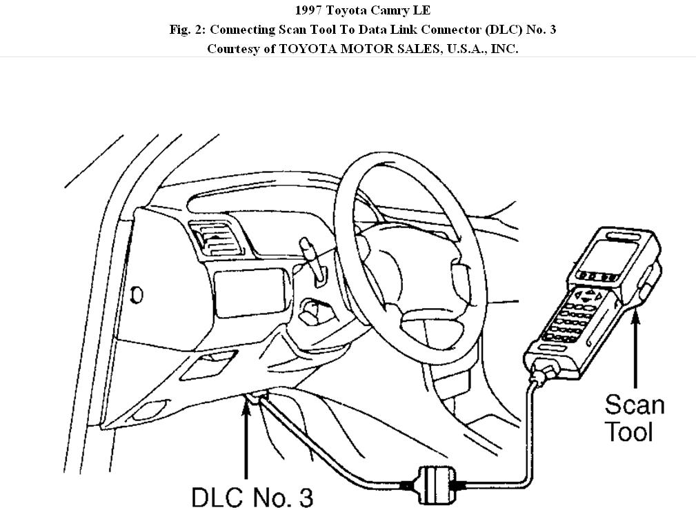
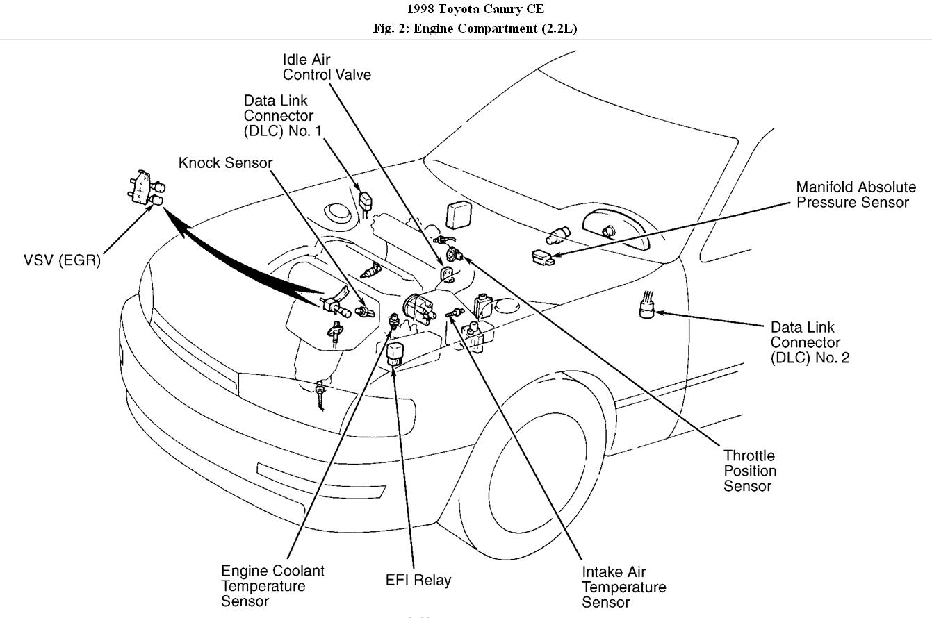
1. Connect scan tool to DLC No. 3 connector. See Fig. 2 . Turn ignition on. Using scan tool, read MAP sensor value. If reading is not same as atmospheric pressure, go to next step. If reading is same as atmospheric pressure, check component and ECM connections. Problem is intermittent.
Fig. 2: Connecting Scan Tool To Data Link Connector (DLC) No. 3
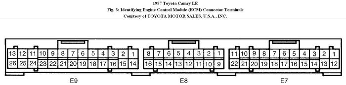
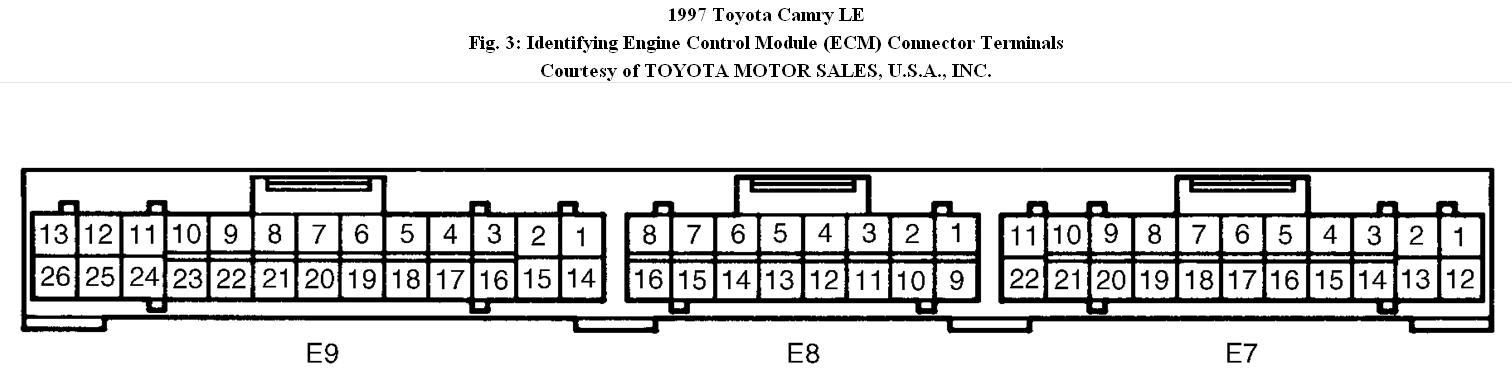
2. Access ECM behind glove box. Turn ignition on. Backprobing ECM connector, measure voltage between terminals No. 1 (Yellow wire) and No. 9 (Brown wire) at ECM E8 connector. See Fig. 3 . If voltage is 4.5-5.5 volts, go to next step. If voltage is not 4.5-5.5 volts, replace ECM and retest.
3. Backprobing ECM connector, measure voltage between terminals No. 2 (Black/Yellow wire) and No. 9 (Brown wire) at ECM E8 connector. If voltage is 3.3-3.9 volts, replace ECM and retest. If voltage is not 3.3-3.9 volts, go to next step.
4. Check for an open or short circuit in wiring harness between MAP sensor and ECM. Repair wiring as necessary. If wiring harness is okay, replace MAP sensor and retest.
Fig. 3: Identifying Engine Control Module (ECM) Connector Terminals
© 2008 Mitchell Repair Information Co., LLC.
P0300 = Random misfire.
P0301 = Cylinder # 1 misfire,
P0304 = Cylinder # 4 misfire.
They could be triggerred by P0105. They could also be due to faulty spark plugs and related components.
CAUTION: If ECM replacement is instructed in following testing, always ensure ECM connectors and ground circuit are okay. If either are suspect, repair and repeat testing to confirm ECM malfunction.
Circuit Description
MAP sensor detects manifold pressure as a voltage that is supplied to ECM. Signal is used to determine basic injection duration and basic injection advance angle. ECM will operate in fail-safe mode if DTC P0105 is set. DTC is set when ECM detects an open or short in MAP circuit.
Possible causes are:
• MAP open or short circuit.
• MAP sensor.
• ECM.
Diagnosis & Repair
1. Connect scan tool to DLC No. 3 connector. See Fig. 2 . Turn ignition on. Using scan tool, read MAP sensor value. If reading is not same as atmospheric pressure, go to next step. If reading is same as atmospheric pressure, check component and ECM connections. Problem is intermittent.
Fig. 2: Connecting Scan Tool To Data Link Connector (DLC) No. 3
2. Access ECM behind glove box. Turn ignition on. Backprobing ECM connector, measure voltage between terminals No. 1 (Yellow wire) and No. 9 (Brown wire) at ECM E8 connector. See Fig. 3 . If voltage is 4.5-5.5 volts, go to next step. If voltage is not 4.5-5.5 volts, replace ECM and retest.
3. Backprobing ECM connector, measure voltage between terminals No. 2 (Black/Yellow wire) and No. 9 (Brown wire) at ECM E8 connector. If voltage is 3.3-3.9 volts, replace ECM and retest. If voltage is not 3.3-3.9 volts, go to next step.
4. Check for an open or short circuit in wiring harness between MAP sensor and ECM. Repair wiring as necessary. If wiring harness is okay, replace MAP sensor and retest.
Fig. 3: Identifying Engine Control Module (ECM) Connector Terminals
© 2008 Mitchell Repair Information Co., LLC.
P0300 = Random misfire.
P0301 = Cylinder # 1 misfire,
P0304 = Cylinder # 4 misfire.
They could be triggerred by P0105. They could also be due to faulty spark plugs and related components.
Images (Click to enlarge)
Feb 11, 2011 at 1:11 PM
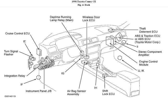
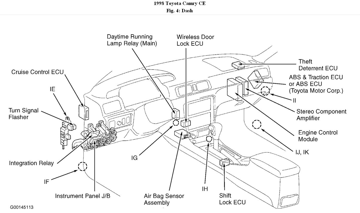
Thanks a lot,Concernig the 98 camry,please can you just give me the diagram of the engine and label things like the MAP sensor,absolute manifold pressure,glove box,ECM so thati will know there location.Again are you saying that the brain box may be faulty or just tell me the part that has the problem so that i can change it bcos i don't have the necessary tools or expertise to test things except it is more detailed which i dont want to border you with but i will be happy if i just know the part to change or repair if possible
Feb 11, 2011 at 5:38 PM
Thanks a lot.For the Ford,pls i have checked the Fuel rail hose and there is no lekage and the Fuel filler cap is well tightened but i can't find the fuel tank pressure sensor or/and the fuel rail sensor perhaps they can cause the fuel pump not to be pumping well.Whenever i plug the switch of the throttle plate,the van does not start but immediately i unplug it it will start but the idling will be rough ie goin up and down and the exhaust will be sounding tututu to show unsteadiness
Feb 11, 2011 at 5:50 PM
Without any diagnostics, you would not be able to verify if any components are faulty and replacing components without confirming they are bad is going to be expensive and frustrating.
Check the MAP sensor vacuum hoses first.
Check the MAP sensor vacuum hoses first.
Images (Click to enlarge)
Feb 11, 2011 at 5:54 PM
I could not find any information as to the exact location of the FTP and it should be at the fuel tank as it is the sensor for measuring the fuel tank pressure.
Feb 11, 2011 at 6:14 PM
Thanks but can it cause the fuel pump not to function well.Is the switch by the throttle body not working causing the van not to start except i remove it
Feb 11, 2011 at 6:37 PM
I believe it is not the FTP but the TPS that is causing the problem.
Feb 11, 2011 at 7:08 PM
Are you suggesting that i change the throttle body.Could this possibly solve all this problem since it will come with the TPS.Or what do you think
Feb 11, 2011 at 7:48 PM
You should start with that as the TPS is showing trouble codes all the time.
Feb 12, 2011 at 11:20 AM
Hi,long time,anyway i finally bought the complete throttle body for the ford bus but it didnt accelerate but i notice that it started quiclkly and it idle without shaking.When i checked several times the codes left are P2104 and P2112 but when at idling Po193 and Po451 flashes but finally they went off and is now left with P2112 and p2104.So please where is the fault now with these 2 DTC.Thanks
Feb 26, 2011 at 11:49 AM
please i forgot to add that the Ford throttle position is 12.4%(percent)maximum.i dont know why it is low like this.thanks
Feb 26, 2011 at 4:42 PM
Those are faults for the Accelerator Pedal Position (APP) sensor and I would suggest getting another APP to test.
Feb 27, 2011 at 11:25 AM
Thanks a lot.Are you saying that P2112 and P2104 are for the accelerator pedal,so i need not to bother myself with the PCM.Is it the switch which the pedal is plugged to or the switch attached to the pedal.Besides sombody said P2112 has to do with the PCM damage or what do you think bcos i have absolute confidence in your expertise advice.Finally if i changed the Accelerator pedal, everything will be over.I remember that when all these started,i loosed the Accelerator Pedal to checked inside and even dried it in the sun,perhaps somtin has spoilt inside.Thanks again
Feb 28, 2011 at 3:13 PM
Please are you talking about the complete pedal itself or the pedal sensor and where is the location of the sensor.Thanks
Feb 28, 2011 at 3:21 PM
Most likely you have damaged the APP when you loosened it. That is the part that you have to replace.
Feb 28, 2011 at 3:32 PM
Refer to diagram for location.
Image (Click to enlarge)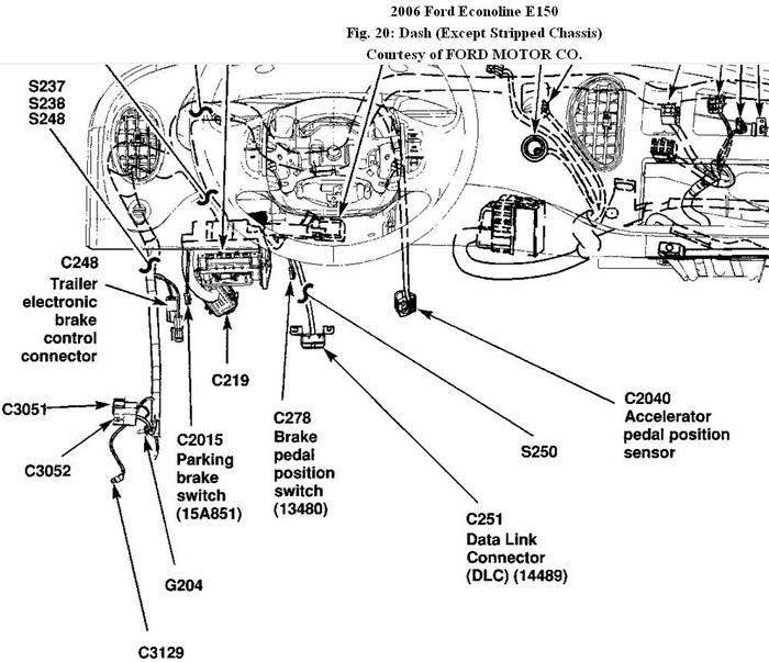

Feb 28, 2011 at 3:39 PM
Thanks but are you saying that it is the complete Accelerator pedal or what do you mean by APP bcos in the diagram i cant find the pedal where we place our legs
Feb 28, 2011 at 3:55 PM
Please you did not tell me if the PCM is not an issue so that i will be sure that i just have to face only the Accelerator Pedal,also you did not talk about the P2104 perhaps it is not an issue.Thanks a lot my brother
Feb 28, 2011 at 5:24 PM
APP is above the accelerator pedal.
The PCM could also be faulty and you need to go step by step. Replacing the TPS have already resolved some problems and the APP might resolve some others. P2104 is also a fault with the APP and you are replacing it so we get to worry about it later if it still appears.
The PCM could also be faulty and you need to go step by step. Replacing the TPS have already resolved some problems and the APP might resolve some others. P2104 is also a fault with the APP and you are replacing it so we get to worry about it later if it still appears.
Mar 1, 2011 at 1:45 PM
Thanks a lot,but whenever i press the accelerator pedal down and start the vehicle it will refuse to start no matter how i try but once i release it it starts immediately.Does it means that there is power or connection to the pedal or its sensor.Besides when the vehicle is idling and i remove the air filter to check the throttle plate it is usually at close position but the vehicle idle normally without shaking unlike the former throttle body.Can you please explain this situation for me to really understand the real problem
Mar 1, 2011 at 4:19 PM
You have a trouble code P2104 and P2112 indicating that the APP is not working correctly. When you use the accelerator pedal the reading is out therefore you would not be able to start. When pedal is not depressed, the reading could be correct allowing vehicle to be started.
Mar 1, 2011 at 6:20 PM
Thanks a lot.Please is it the complete Accelerator Pedal Assembly or just the APP sensor.And where is the location of the sensor,besides is there any test to carry out to know if the APP is bad.Secondly is there any way they test the PCM to know if any circuit has gone bad.
Mar 2, 2011 at 7:22 PM
PINPOINT TEST DK: ACCELERATOR PEDAL POSITION (APP) SENSOR
INTRODUCTION
NOTE: The following DTCs should be diagnosed and repaired through POWERTRAIN DTC CHARTS & DESCRIPTIONS and the appropriate service repair article respectively before entering pinpoint tests DK or DV:
• P0715
• P0720
• P0731-P0735
• P0102-P0104
• P0321
• C1165
• U1027
This pinpoint test is intended to diagnose the following:
• accelerator pedal position (APP) sensor (9F836)
• harness circuits: ETCRTN, SIGRTN, ETCREF, APP1, APP2, and APP3
• powertrain control module (PCM) (12A650)
•
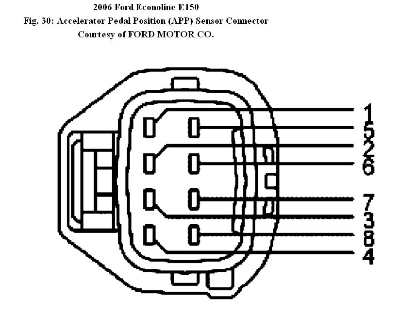
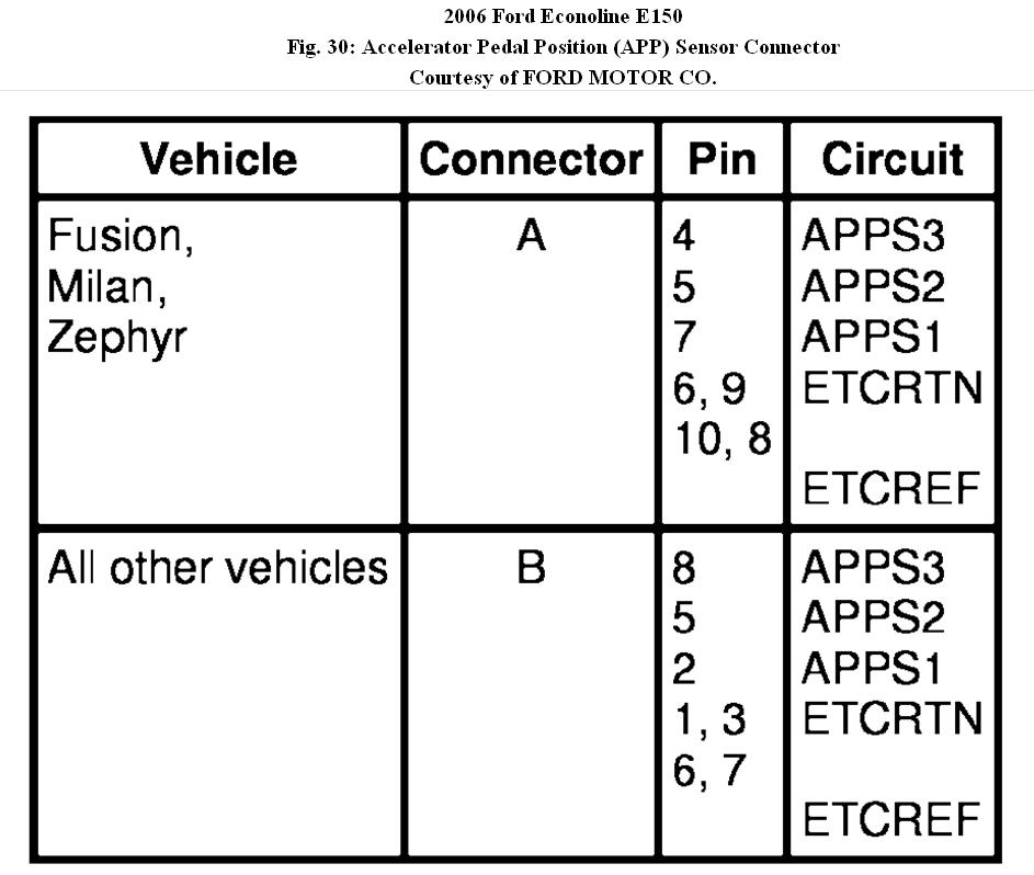
Fig. 30: Accelerator Pedal Position (APP) Sensor Connector
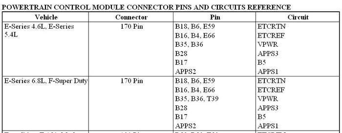
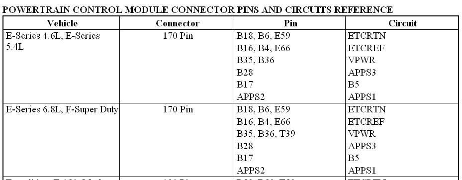
For PCM connector views or reference values, refer to diagram # 3.
TEST PROCEDURE
DK1 CHECK FOR DTCS
Are DTCs P2104, P2121, P2122, P2123, P2126, P2127, P2128, P2131, P2132, or P2133 present?
Yes : GO to DK2.
No : For a lack/loss of power, GO to DK2. For all others, GO to
DIAGNOSTIC TROUBLE CODE (DTC) CHARTS AND DESCRIPTIONS .
DK2 CHECK THE ACCELERATOR PEDAL FOR OBSTRUCTION
• Key ON, engine OFF.
• Press the accelerator pedal fully to the floor and release.
Does the pedal move freely to the floor and back?
Yes : GO to DK3.
No : ISOLATE and REPAIR the obstruction. CLEAR the DTCs. REPEAT the self-test.
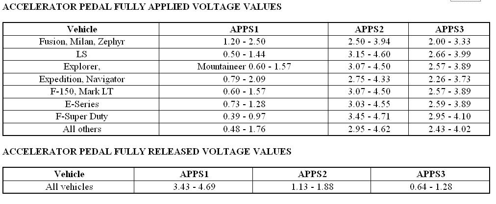
DK3 CHECK THE APP SENSOR SIGNAL VOLTAGE RANGES FOR THE ACCELERATOR PEDAL FULLY APPLIED AND RELEASED POSITIONS
• Access the PCM and monitor the APPS1, APPS2 and APPS3 PIDs.
• Press the accelerator pedal fully to the floor and release.
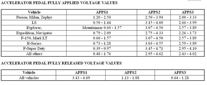
ACCELERATOR PEDAL FULLY APPLIED VOLTAGE VALUES
ACCELERATOR PEDAL FULLY RELEASED VOLTAGE VALUES
(Refer to Diagram # 4)
Are all 3 APPS signals out of range for the pedal fully applied and released positions?
Yes : GO to DK4.
No : For DTCs P2104, P2121, P2122, P2123, P2126, P2127, P2128, P2131, P2132 or P2133 alone, GO to DK8. For any combination of ETC related DTCs, GO to DK4. For continuous memory DTCs P2121 and P2126 with P2131, GO to DK22. For a lack/loss of power, GO to DK8.
DK4 CHECK THE VREF VOLTAGE TO APP SENSOR
• Key in OFF position.
• APP Sensor connector disconnected.
• Key ON, engine OFF.
• Measure the voltage between:
( + ) APP Sensor Connector, Harness Side = ETCREF
( - ) APP Sensor Connector, Harness Side = ETCRTN
Is the voltage between 4 - 6 V?
Yes : GO to DK5.
No : GO to Pinpoint Test C.
DK5 CHECK THE FUNCTIONALITY OF THE APPS1 CIRCUIT
NOTE: Use the voltage measurements from DK3.
Is APPS1 out of range?
Yes : GO to DK8.
No : GO to DK6.
DK6 CHECK THE FUNCTIONALITY OF APPS2
NOTE: Use the voltage measurements from DK3.
Is APPS2 out of range?
Yes : GO to DK8.
No : GO to DK7.
DK7 CHECK THE FUNCTIONALITY OF APPS3
NOTE: Use the voltage measurements from DK3.
Is APPS3 out of range?
Yes : GO to DK8.
No : GO to DK22.
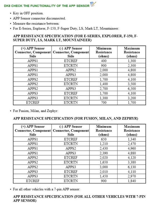
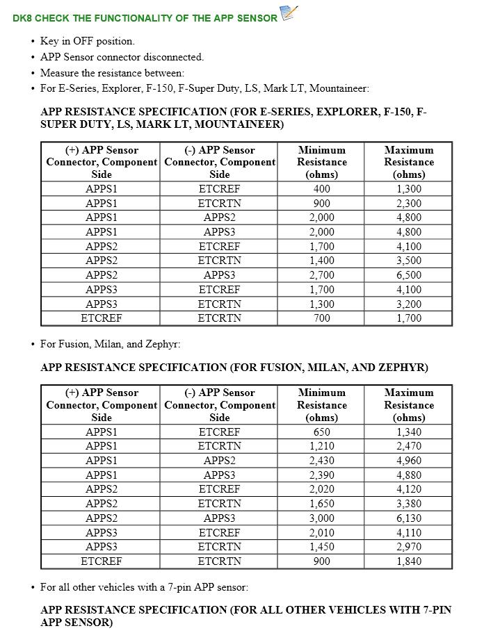
Refer to diagram # 5 for DK8
Are all the resistances within specifications?
Yes : For DTCs P2121, P2122 or P2123 alone or in combination, GO to
DK10.
For DTCs P2126, P2127 or P2128 alone or in combination, GO to DK14.
For DTCs P2131, P2132 or P2133 alone or in combination, GO to DK18.
For DTC P2104 alone, GO to DK26.
For a lack/loss of power, the concern is elsewhere. RETURN to SYMPTOM
CHARTS for further direction.
For all others, GO to DK22.
N0 : INSTALL a new APP sensor. REFER to the appropriate ACCELERATION CONTROL article .
CLEAR the DTCs.
PRESS the accelerator pedal several times and REPEAT the self-test. If DTCs are present:
GO to DK9.
DK9 CHECK THE APP SENSOR CIRCUIT INTEGRITY
• Key in OFF position.
• APP Sensor connector disconnected.
• Measure the resistance between:
( + ) APP Sensor Connector, Component Side = ETCREF
( - ) APP Sensor Connector, Component Side = ETCRTN
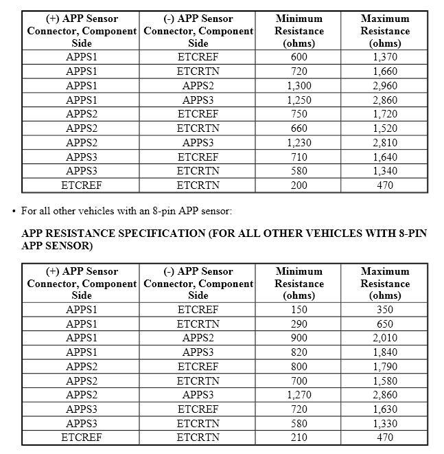
Is the resistance between 700 ohms - 1,700 ohms (E-Series, Explorer, F-150, F-Super Duty, LS, Mark LT, Mountaineer), 900 ohms - 1,840 ohms (Fusion, Milan, Zephyr), 200 ohms - 470 ohms (all other vehicles with a 7-pin APP sensor), or 210 ohms - 470 ohms (all other vehicles with an 8-pin APP sensor)?
Yes : For continuous memory DTCs P2121 with P2122 or P2123, or with P2126 and P2131, GO to DK10.
For continuous memory DTCs P2126 with P2127 or P2128, or with P2121 and P2131, GO to DK14.
For continuous memory DTCs P2121 and P2122 or P2131 and P2133, GO to
DK18.
No : INSTALL a new APP sensor.
CLEAR the DTCs.
PRESS the accelerator pedal several times and REPEAT the self-test. If DTCs are present: GO to DK10.
DK10 CHECK THE APPS1 CIRCUIT FOR AN OPEN IN THE HARNESS
• PCM connector disconnected.
• Measure the resistance between:
( + ) APP Sensor Connector, Harness Side = ( - ) PCM Connector, Harness Side = APPS1
Is the resistance less than 5 ohms?
Yes : GO to DK11.
No : REPAIR the open circuit. CLEAR the DTCs. REPEAT the self-test.
DK11 CHECK THE APPS1 CIRCUIT FOR A SHORT TO GROUND IN THE HARNESS
• Measure the resistance between:
( + ) APP Sensor Connector, Harness Side = APPS1
( - ) 12 Volt Vehicle Battery = Negative terminal
Is the resistance greater than 10K ohms?
Yes : GO to DK12.
No : REPAIR the short circuit to GND. CLEAR the DTCs. REPEAT the self-test.
DK12 CHECK THE APPS1 CIRCUIT FOR A SHORT IN THE HARNESS
• Measure the resistance between:
( + ) APP Sensor Connector, Harness Side = APPS1
( - ) APP Sensor Connector, Harness Side = ETCRTN
( + ) APP Sensor Connector, Harness Side = APPS1
( - ) APP Sensor Connector, Harness Side = ETCREF
Are the resistances greater than 10K ohms?
Yes : GO to DK13.
No : REPAIR the short circuit. CLEAR the DTCs. REPEAT the self-test.
DK13 CHECK THE APPS1 CIRCUIT FOR A SHORT TO VOLTAGE IN THE HARNESS
• Key ON, engine OFF.
• Measure the voltage between:
( + ) APP Sensor Connector, Harness Side = APPS1
( - ) 12 Volt Vehicle Battery = Negative terminal
Is any voltage present?
Yes : REPAIR the short circuit. CLEAR the DTCs. REPEAT the self-test.
No : GO to DK22.
DK14 CHECK THE APPS2 CIRCUIT FOR AN OPEN IN THE HARNESS
• PCM connector disconnected.
• Measure the resistance between:
( + ) APP Sensor Connector, Harness Side = APPS2
( - ) PCM Connector, Harness Side = APPS2
Is the resistance less than 5 ohms?
Yes : GO to DK15.
No : REPAIR the open circuit. CLEAR the DTCs. REPEAT the self-test.
DK15 CHECK THE APPS2 CIRCUIT FOR A SHORT TO GROUND IN THE HARNESS
• Measure the resistance between:
( + ) PCM Connector, Harness Side = APPS2
( - ) 12 Volt Vehicle Battery = Negative terminal
Is the resistance greater than 10K ohms?
Yes : GO to DK16.
No : REPAIR the short circuit to GND. CLEAR the DTCs. REPEAT the self-test.
DK16 CHECK THE APPS2 CIRCUIT FOR A SHORT IN THE HARNESS
• Measure the resistance between:
( + ) APP Sensor Connector, Harness Side = APPS2
( - ) APP Sensor Connector, Harness Side = ETCRTN
( + ) APP Sensor Connector, Harness Side = APPS2
( - ) APP Sensor Connector, Harness Side = ETCREF
Are the resistances greater than 10K ohms?
Yes : GO to DK17.
No : REPAIR the short circuit. CLEAR the DTCs. REPEAT the self-test.
DK17 CHECK THE APPS2 CIRCUIT FOR A SHORT TO VOLTAGE IN THE HARNESS
• Key ON, engine OFF.
• Measure the voltage between:
( + ) PCM Connector, Harness Side = APPS2
( - ) 12 Volt Vehicle Battery = Negative terminal
Is any voltage present?
Yes : REPAIR the short circuit. CLEAR the DTCs. REPEAT the self-test.
No : GO to DK23.
DK18 CHECK THE APPS3 CIRCUIT FOR AN OPEN IN THE HARNESS
• PCM connector disconnected.
• Measure the resistance between:
( + ) APP Sensor Connector, Harness Side = APPS3
( - ) PCM Connector, Harness Side = APPS3
Is the resistance less than 5 ohms?
Yes = GO to DK19.
No : REPAIR the open circuit. CLEAR the DTCs. REPEAT the self-test.
DK19 CHECK THE APPS3 CIRCUIT FOR A SHORT TO GROUND IN THE HARNESS
• Measure the resistance between:
( + ) PCM Connector, Harness Side = APPS3
( - ) 12 Volt Vehicle Battery = Negative terminal
Is the resistance greater than 10K ohms?
Yes : GO to DK20.
No : REPAIR the short circuit to GND. CLEAR the DTCs. REPEAT the self-test.
DK20 CHECK THE APPS3 CIRCUIT FOR A SHORT IN THE HARNESS
• Measure the resistance between:
( + ) APP Sensor Connector, Harness Side = APPS3
( - ) APP Sensor Connector, Harness Side = ETCRTN
( + ) APP Sensor Connector, Harness Side = APPS3
( - ) APP Sensor Connector, Harness Side = ETCREF
Are the resistances greater than 10K ohms?
Yes : GO to DK21.
No : REPAIR the short circuit. CLEAR the DTCs. REPEAT the self-test.
DK21 CHECK THE APPS3 CIRCUIT FOR A SHORT TO VOLTAGE IN THE HARNESS
• Key ON, engine OFF.
• Measure the voltage between:
( + ) PCM Connector, Harness Side = APPS3
( - ) 12 Volt Vehicle Battery = Negative terminal
Is any voltage present?
Yes : REPAIR the short circuit. CLEAR the DTCs. REPEAT the self-test.
N0 : GO to DK24.
DK22 CHECK THE APPS1 CIRCUIT FOR A SHORT TOGETHER
• Key in OFF position.
• PCM connector disconnected.
• APP Sensor connector disconnected.
• Measure the resistance between:
( + ) APP Sensor Connector, Harness Side = APPS1
( - ) APP Sensor Connector, Harness Side = APPS2
( + ) APP Sensor Connector, Harness Side = APPS1
( - ) APP Sensor Connector, Harness Side = APPS3
( + ) APP Sensor Connector, Harness Side = APPS1
( - ) APP Sensor Connector, Harness Side = ETCREF
( + ) APP Sensor Connector, Harness Side = APPS1
( - ) APP Sensor Connector, Harness Side = ETCRTN
Are the resistances greater than 10K ohms?
Yes : GO to DK25.
No : REPAIR the short circuit. CLEAR the DTCs. REPEAT the self-test.
DK23 CHECK FOR THE APPS2 CIRCUIT SHORTED TO SIGNALS IN THE SAME HARNESS
• Key in OFF position.
• Measure the resistance between:
( + ) APP Sensor Connector, Harness Side = APPS2
( - ) APP Sensor Connector, Harness Side = APPS1
( + ) APP Sensor Connector, Harness Side = APPS2
( - ) APP Sensor Connector, Harness Side = APPS3
( + ) APP Sensor Connector, Harness Side = APPS2
( - ) APP Sensor Connector, Harness Side = ETCREF
( + ) APP Sensor Connector, Harness Side = APPS2
( - ) APP Sensor Connector, Harness Side = ETCRTN
Are the resistances greater than 10K ohms?
Yes : GO to DK25.
No : EPAIR the short circuit. CLEAR the DTCs. REPEAT the self-test.
DK24 CHECK FOR THE APPS3 CIRCUIT SHORTED TO SIGNALS IN THE SAME HARNESS
• Key in OFF position.
• Measure the resistance between:
( + ) APP Sensor Connector, Harness Side = APPS3
( - ) APP Sensor Connector, Harness Side = APPS1
( + ) APP Sensor Connector, Harness Side = APPS3
( - ) APP Sensor Connector, Harness Side = APPS2
( + ) APP Sensor Connector, Harness Side = APPS3
( - ) APP Sensor Connector, Harness Side = ETCREF
( + ) APP Sensor Connector, Harness Side = APPS3
( - ) APP Sensor Connector, Harness Side = ETCRTN
Are the resistances greater than 10K ohms?
Yes : GO to DK25.
no : REPAIR the short circuit. CLEAR the DTCs. REPEAT the self-test.
DK25 CHECK THE APP SENSOR CIRCUITS FOR AN INTERMITTENT CONCERN
• Wiggle, shake, and bend small sections of the wiring harness while working from the sensor to the PCM.
• Measure the resistance between:
( + ) APP Sensor Connector, Harness Side = APPS1
( - ) PCM Connector, Harness Side = APPS1
( + ) APP Sensor Connector, Harness Side = APPS2
( - ) PCM Connector, Harness Side = APPS2
( + ) APP Sensor Connector, Harness Side = APPS3
( - ) PCM Connector, Harness Side = APPS3
Are the resistances less than 5 ohms?
Yes : GO to DK26.
No : ISOLATE the concern and REPAIR as necessary. CLEAR the DTCs. REPEAT the self-test.
DK26 CHECK FOR CORRECT PCM OPERATION
• Disconnect all the PCM connectors.
• Visually inspect for:
a) pushed out pins
b) corrosion
• Connect all the PCM connectors and make sure they seat correctly.
• Carry out the PCM self-test and verify the concern is still present.
Is the concern still present?
Yes : INSTALL a new PCM. REFER to FLASH ELECTRICALLY ERASABLE PROGRAMMABLE READ ONLY MEMORY (EEPROM) .
N0 : The system is operating correctly at this time. The concern may have been caused by a loose or corroded connector.
© 2008 Mitchell Repair Information Co., LLC.
INTRODUCTION
NOTE: The following DTCs should be diagnosed and repaired through POWERTRAIN DTC CHARTS & DESCRIPTIONS and the appropriate service repair article respectively before entering pinpoint tests DK or DV:
• P0715
• P0720
• P0731-P0735
• P0102-P0104
• P0321
• C1165
• U1027
This pinpoint test is intended to diagnose the following:
• accelerator pedal position (APP) sensor (9F836)
• harness circuits: ETCRTN, SIGRTN, ETCREF, APP1, APP2, and APP3
• powertrain control module (PCM) (12A650)
•
Fig. 30: Accelerator Pedal Position (APP) Sensor Connector
For PCM connector views or reference values, refer to diagram # 3.
TEST PROCEDURE
DK1 CHECK FOR DTCS
Are DTCs P2104, P2121, P2122, P2123, P2126, P2127, P2128, P2131, P2132, or P2133 present?
Yes : GO to DK2.
No : For a lack/loss of power, GO to DK2. For all others, GO to
DIAGNOSTIC TROUBLE CODE (DTC) CHARTS AND DESCRIPTIONS .
DK2 CHECK THE ACCELERATOR PEDAL FOR OBSTRUCTION
• Key ON, engine OFF.
• Press the accelerator pedal fully to the floor and release.
Does the pedal move freely to the floor and back?
Yes : GO to DK3.
No : ISOLATE and REPAIR the obstruction. CLEAR the DTCs. REPEAT the self-test.
DK3 CHECK THE APP SENSOR SIGNAL VOLTAGE RANGES FOR THE ACCELERATOR PEDAL FULLY APPLIED AND RELEASED POSITIONS
• Access the PCM and monitor the APPS1, APPS2 and APPS3 PIDs.
• Press the accelerator pedal fully to the floor and release.
ACCELERATOR PEDAL FULLY APPLIED VOLTAGE VALUES
ACCELERATOR PEDAL FULLY RELEASED VOLTAGE VALUES
(Refer to Diagram # 4)
Are all 3 APPS signals out of range for the pedal fully applied and released positions?
Yes : GO to DK4.
No : For DTCs P2104, P2121, P2122, P2123, P2126, P2127, P2128, P2131, P2132 or P2133 alone, GO to DK8. For any combination of ETC related DTCs, GO to DK4. For continuous memory DTCs P2121 and P2126 with P2131, GO to DK22. For a lack/loss of power, GO to DK8.
DK4 CHECK THE VREF VOLTAGE TO APP SENSOR
• Key in OFF position.
• APP Sensor connector disconnected.
• Key ON, engine OFF.
• Measure the voltage between:
( + ) APP Sensor Connector, Harness Side = ETCREF
( - ) APP Sensor Connector, Harness Side = ETCRTN
Is the voltage between 4 - 6 V?
Yes : GO to DK5.
No : GO to Pinpoint Test C.
DK5 CHECK THE FUNCTIONALITY OF THE APPS1 CIRCUIT
NOTE: Use the voltage measurements from DK3.
Is APPS1 out of range?
Yes : GO to DK8.
No : GO to DK6.
DK6 CHECK THE FUNCTIONALITY OF APPS2
NOTE: Use the voltage measurements from DK3.
Is APPS2 out of range?
Yes : GO to DK8.
No : GO to DK7.
DK7 CHECK THE FUNCTIONALITY OF APPS3
NOTE: Use the voltage measurements from DK3.
Is APPS3 out of range?
Yes : GO to DK8.
No : GO to DK22.
Refer to diagram # 5 for DK8
Are all the resistances within specifications?
Yes : For DTCs P2121, P2122 or P2123 alone or in combination, GO to
DK10.
For DTCs P2126, P2127 or P2128 alone or in combination, GO to DK14.
For DTCs P2131, P2132 or P2133 alone or in combination, GO to DK18.
For DTC P2104 alone, GO to DK26.
For a lack/loss of power, the concern is elsewhere. RETURN to SYMPTOM
CHARTS for further direction.
For all others, GO to DK22.
N0 : INSTALL a new APP sensor. REFER to the appropriate ACCELERATION CONTROL article .
CLEAR the DTCs.
PRESS the accelerator pedal several times and REPEAT the self-test. If DTCs are present:
GO to DK9.
DK9 CHECK THE APP SENSOR CIRCUIT INTEGRITY
• Key in OFF position.
• APP Sensor connector disconnected.
• Measure the resistance between:
( + ) APP Sensor Connector, Component Side = ETCREF
( - ) APP Sensor Connector, Component Side = ETCRTN
Is the resistance between 700 ohms - 1,700 ohms (E-Series, Explorer, F-150, F-Super Duty, LS, Mark LT, Mountaineer), 900 ohms - 1,840 ohms (Fusion, Milan, Zephyr), 200 ohms - 470 ohms (all other vehicles with a 7-pin APP sensor), or 210 ohms - 470 ohms (all other vehicles with an 8-pin APP sensor)?
Yes : For continuous memory DTCs P2121 with P2122 or P2123, or with P2126 and P2131, GO to DK10.
For continuous memory DTCs P2126 with P2127 or P2128, or with P2121 and P2131, GO to DK14.
For continuous memory DTCs P2121 and P2122 or P2131 and P2133, GO to
DK18.
No : INSTALL a new APP sensor.
CLEAR the DTCs.
PRESS the accelerator pedal several times and REPEAT the self-test. If DTCs are present: GO to DK10.
DK10 CHECK THE APPS1 CIRCUIT FOR AN OPEN IN THE HARNESS
• PCM connector disconnected.
• Measure the resistance between:
( + ) APP Sensor Connector, Harness Side = ( - ) PCM Connector, Harness Side = APPS1
Is the resistance less than 5 ohms?
Yes : GO to DK11.
No : REPAIR the open circuit. CLEAR the DTCs. REPEAT the self-test.
DK11 CHECK THE APPS1 CIRCUIT FOR A SHORT TO GROUND IN THE HARNESS
• Measure the resistance between:
( + ) APP Sensor Connector, Harness Side = APPS1
( - ) 12 Volt Vehicle Battery = Negative terminal
Is the resistance greater than 10K ohms?
Yes : GO to DK12.
No : REPAIR the short circuit to GND. CLEAR the DTCs. REPEAT the self-test.
DK12 CHECK THE APPS1 CIRCUIT FOR A SHORT IN THE HARNESS
• Measure the resistance between:
( + ) APP Sensor Connector, Harness Side = APPS1
( - ) APP Sensor Connector, Harness Side = ETCRTN
( + ) APP Sensor Connector, Harness Side = APPS1
( - ) APP Sensor Connector, Harness Side = ETCREF
Are the resistances greater than 10K ohms?
Yes : GO to DK13.
No : REPAIR the short circuit. CLEAR the DTCs. REPEAT the self-test.
DK13 CHECK THE APPS1 CIRCUIT FOR A SHORT TO VOLTAGE IN THE HARNESS
• Key ON, engine OFF.
• Measure the voltage between:
( + ) APP Sensor Connector, Harness Side = APPS1
( - ) 12 Volt Vehicle Battery = Negative terminal
Is any voltage present?
Yes : REPAIR the short circuit. CLEAR the DTCs. REPEAT the self-test.
No : GO to DK22.
DK14 CHECK THE APPS2 CIRCUIT FOR AN OPEN IN THE HARNESS
• PCM connector disconnected.
• Measure the resistance between:
( + ) APP Sensor Connector, Harness Side = APPS2
( - ) PCM Connector, Harness Side = APPS2
Is the resistance less than 5 ohms?
Yes : GO to DK15.
No : REPAIR the open circuit. CLEAR the DTCs. REPEAT the self-test.
DK15 CHECK THE APPS2 CIRCUIT FOR A SHORT TO GROUND IN THE HARNESS
• Measure the resistance between:
( + ) PCM Connector, Harness Side = APPS2
( - ) 12 Volt Vehicle Battery = Negative terminal
Is the resistance greater than 10K ohms?
Yes : GO to DK16.
No : REPAIR the short circuit to GND. CLEAR the DTCs. REPEAT the self-test.
DK16 CHECK THE APPS2 CIRCUIT FOR A SHORT IN THE HARNESS
• Measure the resistance between:
( + ) APP Sensor Connector, Harness Side = APPS2
( - ) APP Sensor Connector, Harness Side = ETCRTN
( + ) APP Sensor Connector, Harness Side = APPS2
( - ) APP Sensor Connector, Harness Side = ETCREF
Are the resistances greater than 10K ohms?
Yes : GO to DK17.
No : REPAIR the short circuit. CLEAR the DTCs. REPEAT the self-test.
DK17 CHECK THE APPS2 CIRCUIT FOR A SHORT TO VOLTAGE IN THE HARNESS
• Key ON, engine OFF.
• Measure the voltage between:
( + ) PCM Connector, Harness Side = APPS2
( - ) 12 Volt Vehicle Battery = Negative terminal
Is any voltage present?
Yes : REPAIR the short circuit. CLEAR the DTCs. REPEAT the self-test.
No : GO to DK23.
DK18 CHECK THE APPS3 CIRCUIT FOR AN OPEN IN THE HARNESS
• PCM connector disconnected.
• Measure the resistance between:
( + ) APP Sensor Connector, Harness Side = APPS3
( - ) PCM Connector, Harness Side = APPS3
Is the resistance less than 5 ohms?
Yes = GO to DK19.
No : REPAIR the open circuit. CLEAR the DTCs. REPEAT the self-test.
DK19 CHECK THE APPS3 CIRCUIT FOR A SHORT TO GROUND IN THE HARNESS
• Measure the resistance between:
( + ) PCM Connector, Harness Side = APPS3
( - ) 12 Volt Vehicle Battery = Negative terminal
Is the resistance greater than 10K ohms?
Yes : GO to DK20.
No : REPAIR the short circuit to GND. CLEAR the DTCs. REPEAT the self-test.
DK20 CHECK THE APPS3 CIRCUIT FOR A SHORT IN THE HARNESS
• Measure the resistance between:
( + ) APP Sensor Connector, Harness Side = APPS3
( - ) APP Sensor Connector, Harness Side = ETCRTN
( + ) APP Sensor Connector, Harness Side = APPS3
( - ) APP Sensor Connector, Harness Side = ETCREF
Are the resistances greater than 10K ohms?
Yes : GO to DK21.
No : REPAIR the short circuit. CLEAR the DTCs. REPEAT the self-test.
DK21 CHECK THE APPS3 CIRCUIT FOR A SHORT TO VOLTAGE IN THE HARNESS
• Key ON, engine OFF.
• Measure the voltage between:
( + ) PCM Connector, Harness Side = APPS3
( - ) 12 Volt Vehicle Battery = Negative terminal
Is any voltage present?
Yes : REPAIR the short circuit. CLEAR the DTCs. REPEAT the self-test.
N0 : GO to DK24.
DK22 CHECK THE APPS1 CIRCUIT FOR A SHORT TOGETHER
• Key in OFF position.
• PCM connector disconnected.
• APP Sensor connector disconnected.
• Measure the resistance between:
( + ) APP Sensor Connector, Harness Side = APPS1
( - ) APP Sensor Connector, Harness Side = APPS2
( + ) APP Sensor Connector, Harness Side = APPS1
( - ) APP Sensor Connector, Harness Side = APPS3
( + ) APP Sensor Connector, Harness Side = APPS1
( - ) APP Sensor Connector, Harness Side = ETCREF
( + ) APP Sensor Connector, Harness Side = APPS1
( - ) APP Sensor Connector, Harness Side = ETCRTN
Are the resistances greater than 10K ohms?
Yes : GO to DK25.
No : REPAIR the short circuit. CLEAR the DTCs. REPEAT the self-test.
DK23 CHECK FOR THE APPS2 CIRCUIT SHORTED TO SIGNALS IN THE SAME HARNESS
• Key in OFF position.
• Measure the resistance between:
( + ) APP Sensor Connector, Harness Side = APPS2
( - ) APP Sensor Connector, Harness Side = APPS1
( + ) APP Sensor Connector, Harness Side = APPS2
( - ) APP Sensor Connector, Harness Side = APPS3
( + ) APP Sensor Connector, Harness Side = APPS2
( - ) APP Sensor Connector, Harness Side = ETCREF
( + ) APP Sensor Connector, Harness Side = APPS2
( - ) APP Sensor Connector, Harness Side = ETCRTN
Are the resistances greater than 10K ohms?
Yes : GO to DK25.
No : EPAIR the short circuit. CLEAR the DTCs. REPEAT the self-test.
DK24 CHECK FOR THE APPS3 CIRCUIT SHORTED TO SIGNALS IN THE SAME HARNESS
• Key in OFF position.
• Measure the resistance between:
( + ) APP Sensor Connector, Harness Side = APPS3
( - ) APP Sensor Connector, Harness Side = APPS1
( + ) APP Sensor Connector, Harness Side = APPS3
( - ) APP Sensor Connector, Harness Side = APPS2
( + ) APP Sensor Connector, Harness Side = APPS3
( - ) APP Sensor Connector, Harness Side = ETCREF
( + ) APP Sensor Connector, Harness Side = APPS3
( - ) APP Sensor Connector, Harness Side = ETCRTN
Are the resistances greater than 10K ohms?
Yes : GO to DK25.
no : REPAIR the short circuit. CLEAR the DTCs. REPEAT the self-test.
DK25 CHECK THE APP SENSOR CIRCUITS FOR AN INTERMITTENT CONCERN
• Wiggle, shake, and bend small sections of the wiring harness while working from the sensor to the PCM.
• Measure the resistance between:
( + ) APP Sensor Connector, Harness Side = APPS1
( - ) PCM Connector, Harness Side = APPS1
( + ) APP Sensor Connector, Harness Side = APPS2
( - ) PCM Connector, Harness Side = APPS2
( + ) APP Sensor Connector, Harness Side = APPS3
( - ) PCM Connector, Harness Side = APPS3
Are the resistances less than 5 ohms?
Yes : GO to DK26.
No : ISOLATE the concern and REPAIR as necessary. CLEAR the DTCs. REPEAT the self-test.
DK26 CHECK FOR CORRECT PCM OPERATION
• Disconnect all the PCM connectors.
• Visually inspect for:
a) pushed out pins
b) corrosion
• Connect all the PCM connectors and make sure they seat correctly.
• Carry out the PCM self-test and verify the concern is still present.
Is the concern still present?
Yes : INSTALL a new PCM. REFER to FLASH ELECTRICALLY ERASABLE PROGRAMMABLE READ ONLY MEMORY (EEPROM) .
N0 : The system is operating correctly at this time. The concern may have been caused by a loose or corroded connector.
© 2008 Mitchell Repair Information Co., LLC.
Images (Click to enlarge)

Mar 3, 2011 at 10:15 PM
Hi,long time no communication my good friend.I have changed the Complete Accelerator pedal(new from ford),i also bought the brain box but fix it without reprogramming but the van started and idle fine without shaking even with A/C on.But yet there is no acceleration.As you know before i have changed the Throttle Body(used but good).This codes are still present:P2104,P2112 and Po193.Thanks a lot for your patience
Jun 3, 2011 at 3:27 PM
Sorry please i forgot to add that i used to hear one kind of clicking sound by the throttle body each time i open the ignition to start the vehicle.Again bear in mind that the throttle body is a used one.thanks
Jun 3, 2011 at 5:14 PM
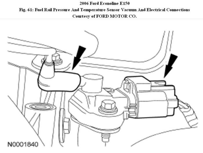
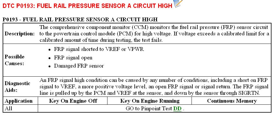
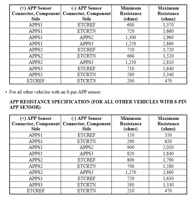
Refer to diagram for explanation of P0193.
As to the other 2 other coeds, check the wireharness. Seems someone has encountered such problems before and was found to be due to damaged wiring. Check the wireharness underhood, near the EGR pipe. Note if the wire is brushing against the EGR pipe and has signs of damage to the wires.
As to the other 2 other coeds, check the wireharness. Seems someone has encountered such problems before and was found to be due to damaged wiring. Check the wireharness underhood, near the EGR pipe. Note if the wire is brushing against the EGR pipe and has signs of damage to the wires.
Image (Click to enlarge)

Jun 4, 2011 at 7:13 AM
Thanks my man,i think this make a lot of sense,i will do that immediately but i need to know the type of wires you are talking about.Again do you think from experience that the Po193 codes has anything to do with the non-accelerating problems.Secondly,do you thing that i need to reprogramme the PCM i bought,although it has the same number and pins and it started the vehicle when fixed.With the explanation on the smooth idling of the vehicle,do you also think the Throttle position sensor by the TB is faulty again.Lastly,please comment on the clicking sound by the TB plug-in connection (i.e 2 wires to the motor side).Thanks
Jun 6, 2011 at 4:14 PM
Yes, P0193 can cause poor throttle response as the fuel pressure sensor is not working correctly.
Since the computer works, it is not necessary to reprograme it but there have been instances whereby reflashing helps.
The wires mentioned are those that is in a harness that goes near the EGR pipes and it could also be the reason for P0193.
The TB would have minimal clicking noise when ignition is turned on as it tries to adjust itself to the conditions such as engine coolant temperature so it is nothing to worry about.
Jun 6, 2011 at 8:05 PM
Thanks for this wonderful reply.I noticed that when i removed the fuel filter to chec for blockage and it was very clean,but as i put on the ignition to check the fuel pressure,fuel refuse to flow at all but if i try to start it it will just be flowing slowly.I tried this several times and it is the same ;i thought it is normal.Or must one start this model of vehicle before fuel flows from the tank?Anyway,please comment on the above and the location of the fuel pressure sensor.Also the location of the EGR pipe.I think we are close to the solution.Finally from the workings of the engine(no hesitation and stumbling during idling)do u think the TPS is ok?Thanks a lot my man.
Jun 8, 2011 at 3:40 PM