Hi,
Thanks for getting back to me so quickly.
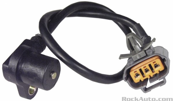
Where did you buy the distributor from?
I ordered it from RockAuto. I checked, and yes it's still under warranty so I can get a replacement at no cost (other than the cost of shipping the defective part back)
Have you scanned the computer for trouble codes?
Yes, I have an OBD2 reader, but it didn't display any fault codes.
Also check your primary and secondary resistance value.
Primary Coil TerminalsResistancePos (+) to Neg (-)0.58-0.86 ohms
Secondary Coil TerminalsResistancePos (+) to High Voltage1.15-18.5 K ohms
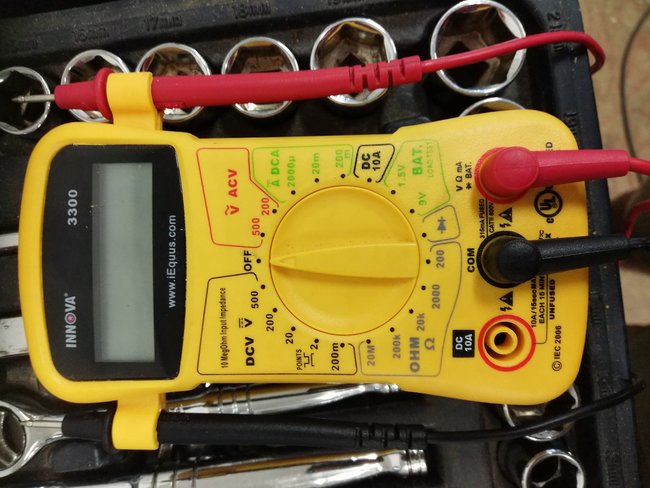
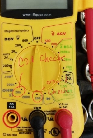
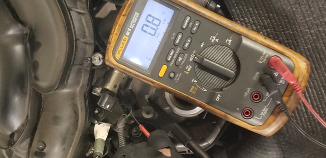
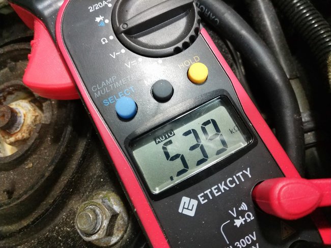
I'm not that familiar with using a voltage meter so I've attached a picture of my meter. You'll see that there are 5 different options in the Ohm section and depending on which setting I choose I get a different reading for each. Are you able to tell me which setting I should be on for each of the 2 readings you wanted me to take? Also, the readings don't appear to static. They seem to always be changing. Is this to be expected?
Also check to see if the injectors are pulsing?
I haven't gotten to this yet, but I do know that when I try cranking the engine fuel is getting to the cylinders as the plugs are wet after pulling them.
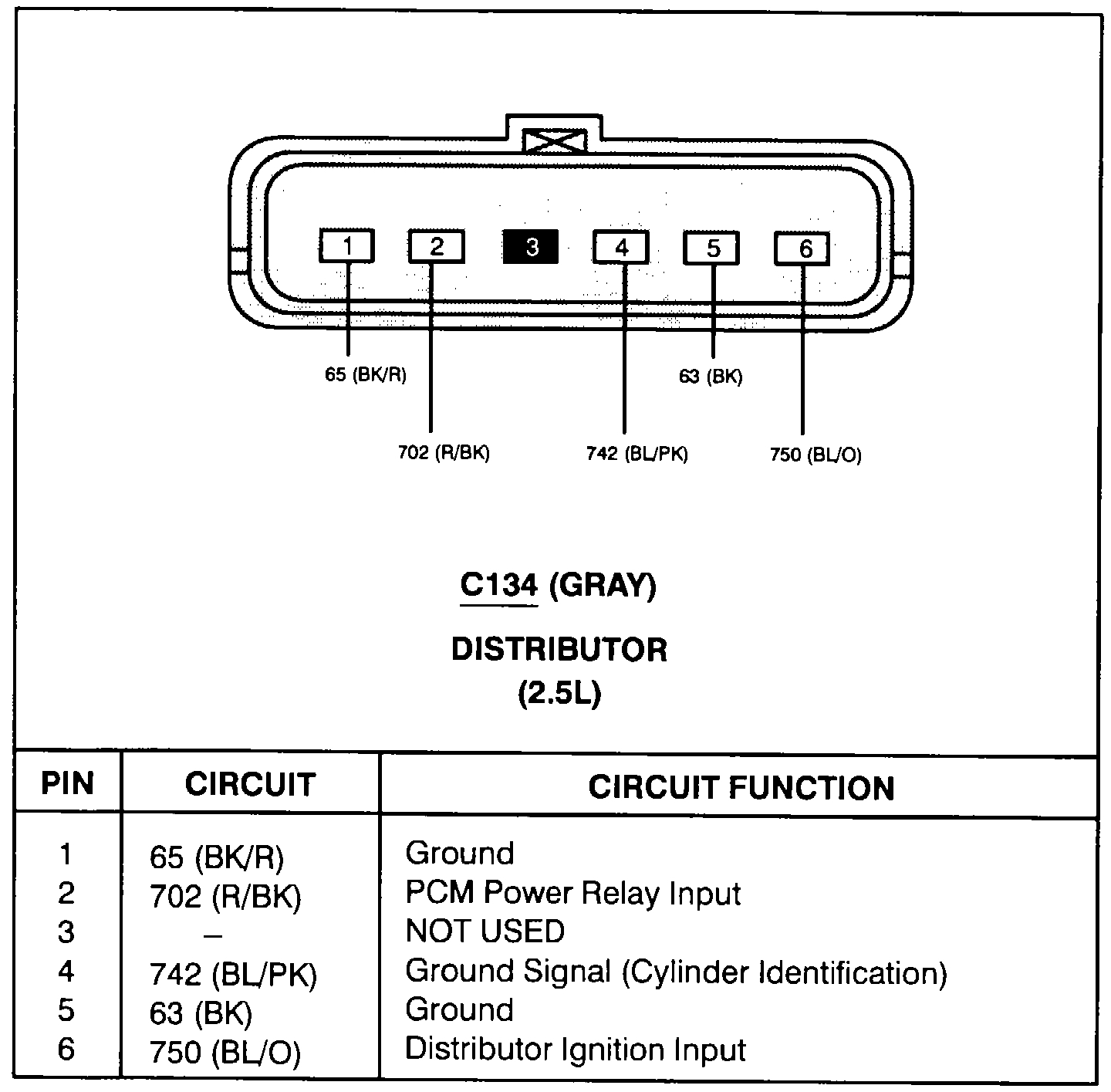
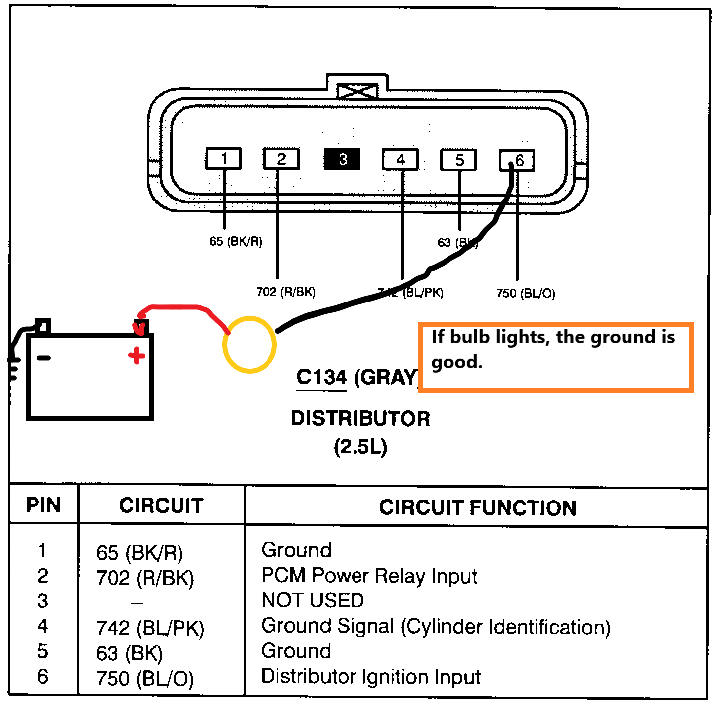
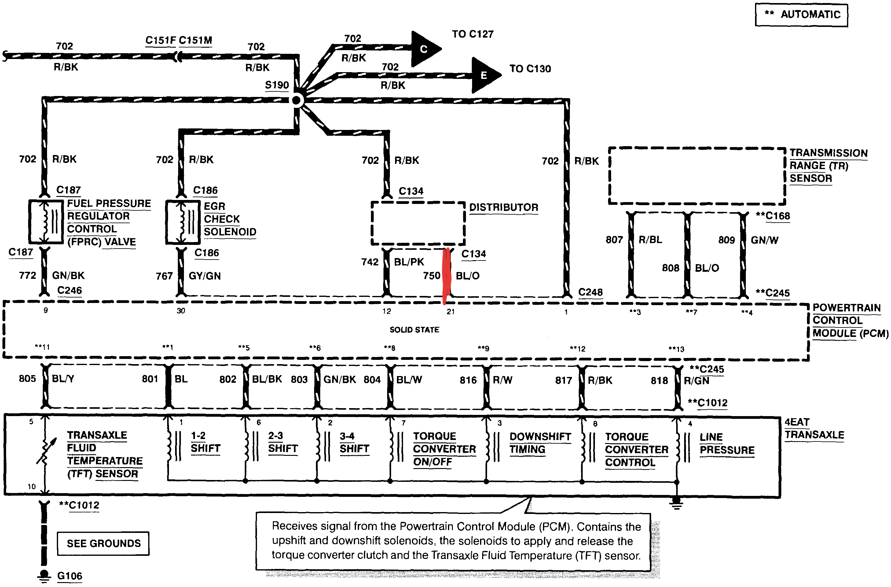
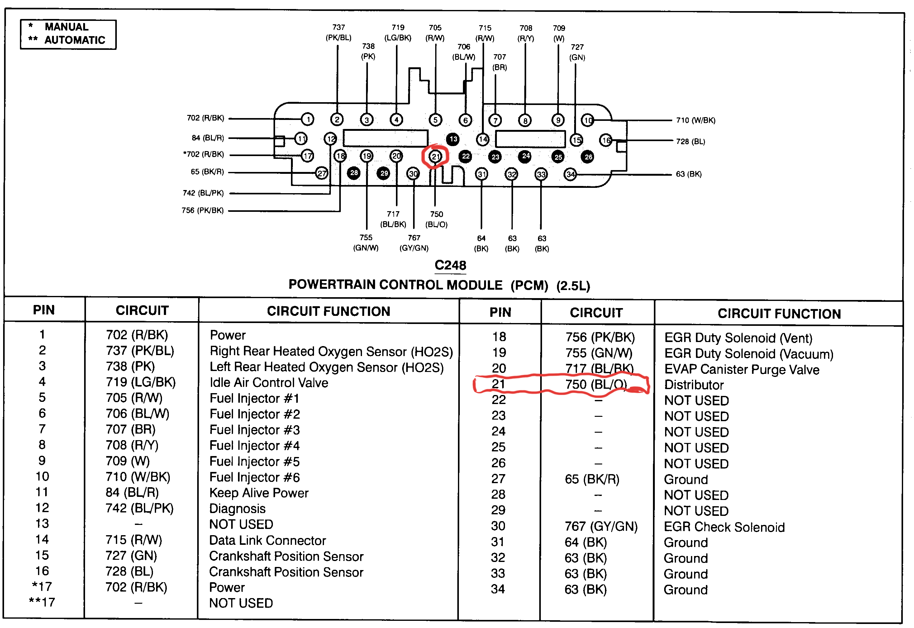
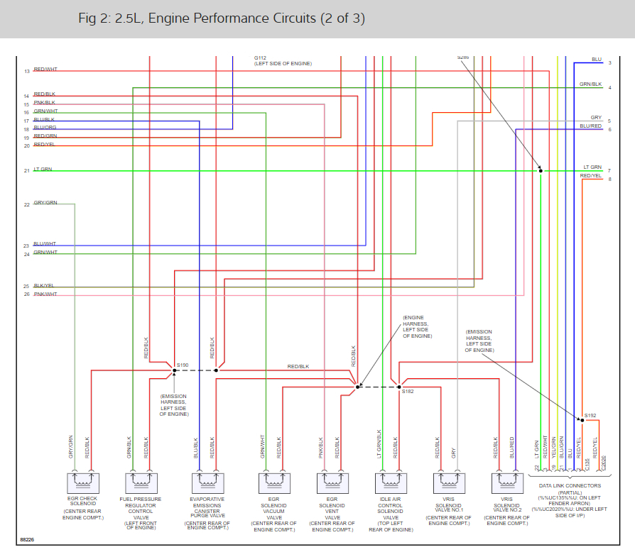
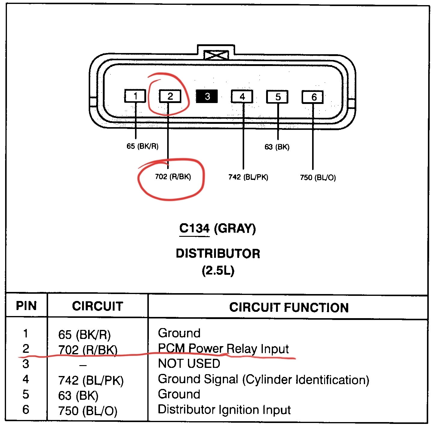
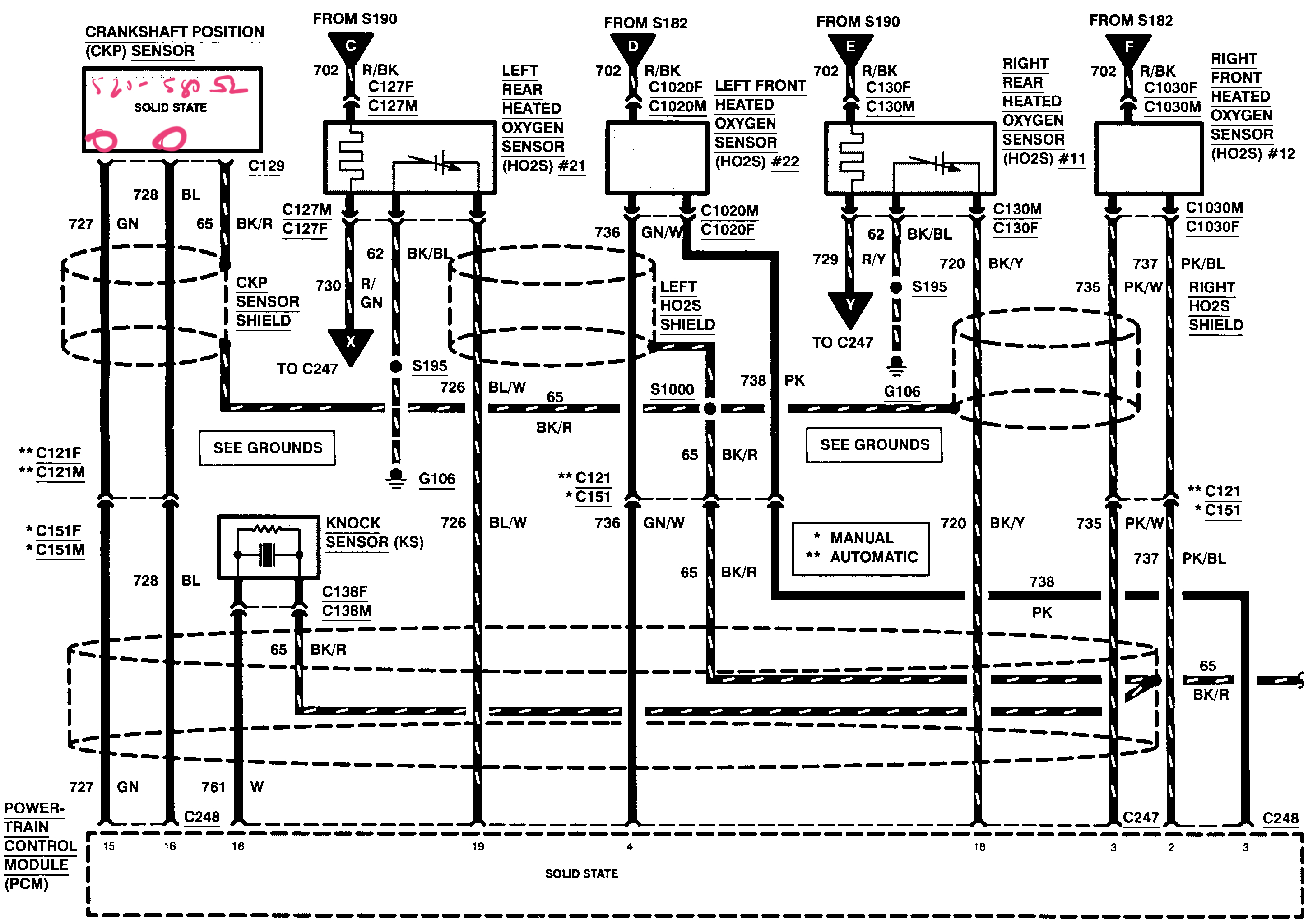
Also since you verified power to the connector, check your grounds as well at pins #1 and #5. Check continuity from that pin to body ground. A good wire should measure under 1 ohm.
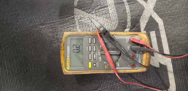
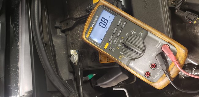
Once again, I'm not 100% certain I've done this right on my meter. I've assumed that the continuity setting on my meter is at the bottom on the right side of center. The reading I got for both pin 1 and 5 was 1200. Does that make any sense to you?
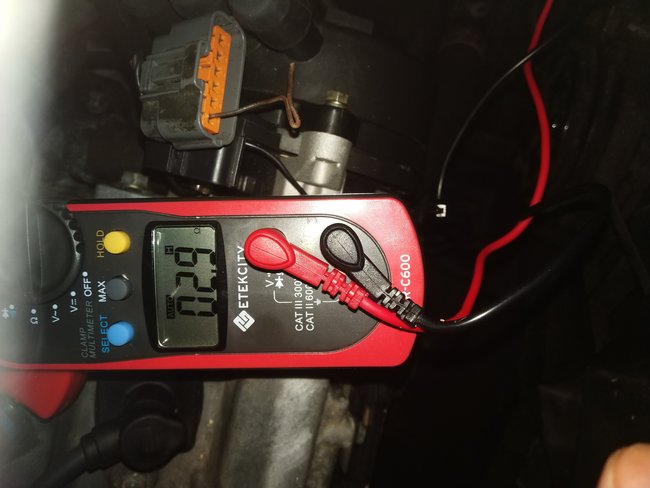
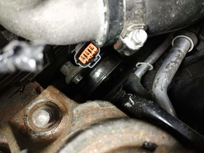
Also, when I confirmed power to the coil I checked for power on the 3 pin connector, not this 6 pin connector. Does that mean I should check for power on pin 6 of the 6 pin connector?
Thanks for all your help so far.
Kevin
Sep 8, 2019 at 8:15 PM