If you got continuity at the correct points based on gear selection, then I'm wrong and the switch is not bad. That leads us to a diagnostic flow chart to help identify the issue. This is extensive, but it needs done. All attached pictures correlate with these directions.
______________________________________________________________
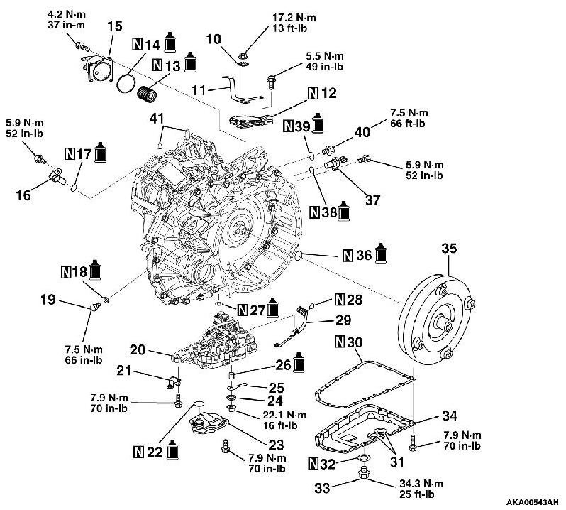
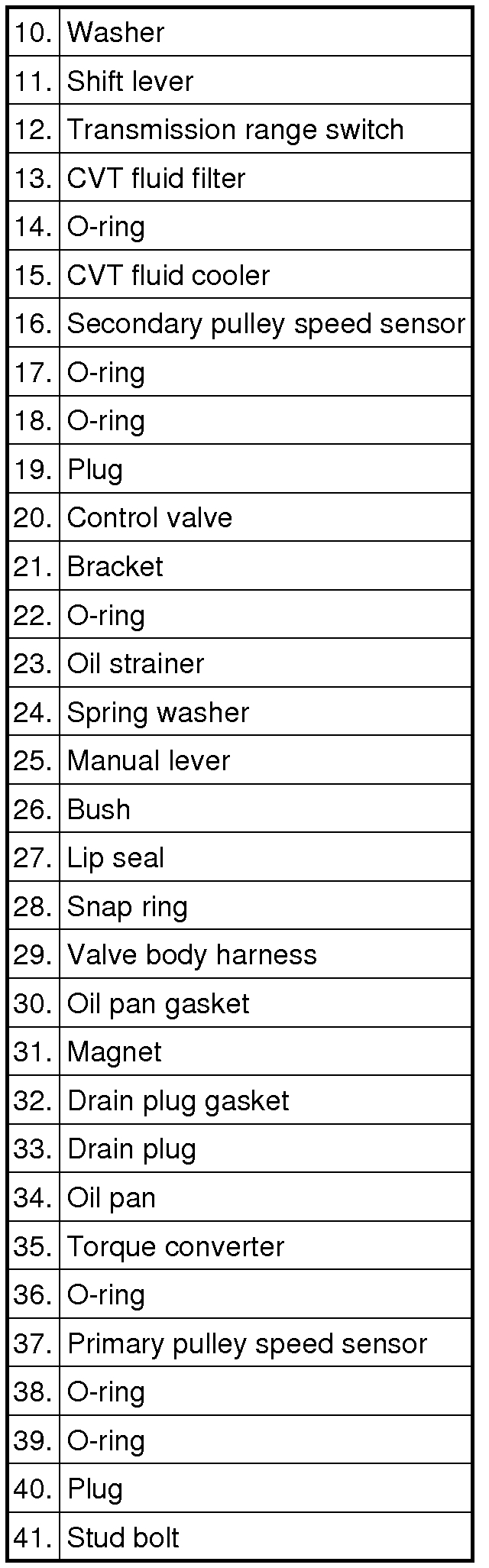
DTC P0705: Malfunction of Transmission Range Switch
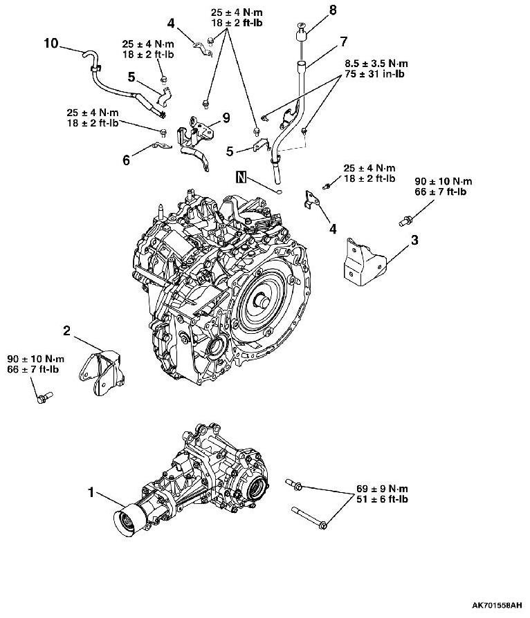
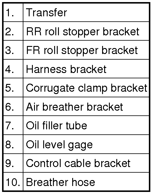
Picture 1
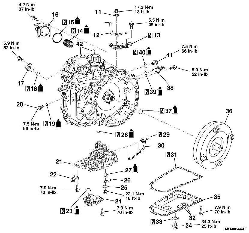
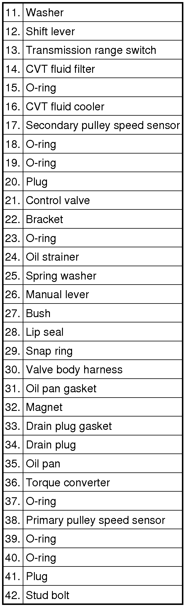
Picture 2
Picture 3
Picture 4
Picture 5
Picture 6
DIAGNOSTIC FUNCTION
TCM monitors the signal from the transmission range switch, and determines if the abnormal input is present or not.
DESCRIPTIONS OF MONITOR METHODS
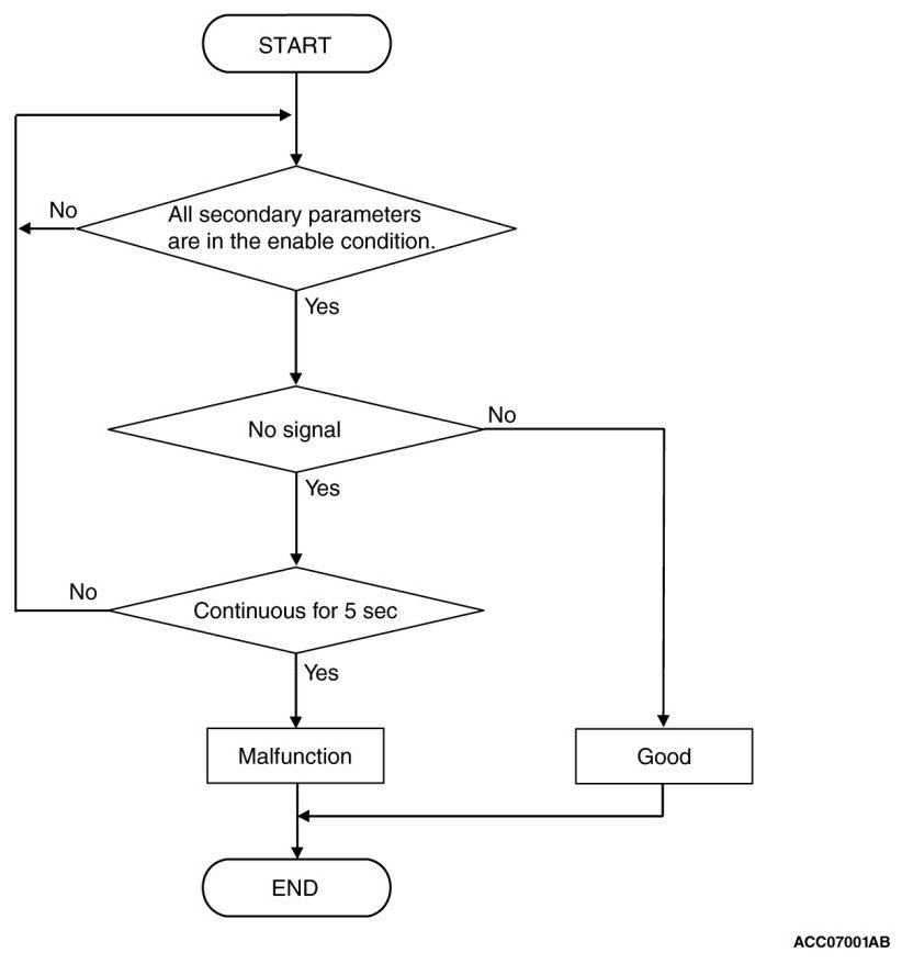
- TCM does not detects the transmission range switch input signal for 5 seconds when the vehicle speed is 1 km/h (0.6 mph) or more for 10 seconds continuously.
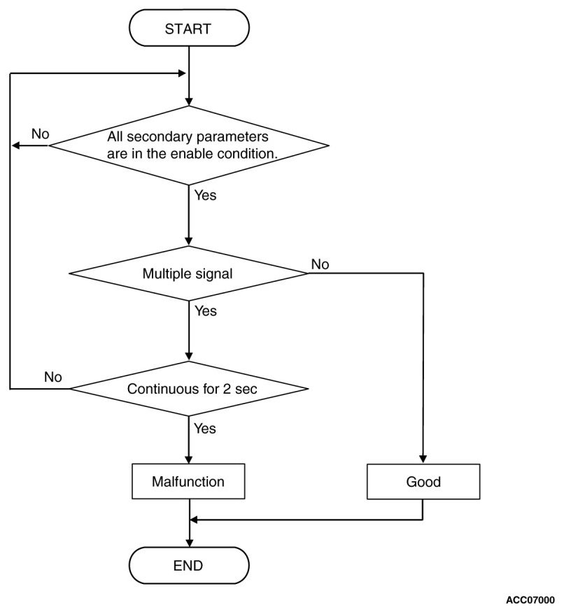
- TCM detects the multiple inputs from the transmission range switch for 2 seconds.
MONITOR EXECUTION
- Vehicle speed (no-transmission range switch signal input): 1km/h (0.6 mph) or more for 10 seconds continuously
- Vehicle speed (transmission range switch signal multiple input): No conditions
- Throttle valve opening: 1/8 or more
- Engine speed: 450 r/min or more
MONITOR EXECUTION CONDITIONS (OTHER MONITOR AND SENSOR)
Other Monitor (There is no temporary DTC stored in memory for the item monitored below)
- P0712, P0713: Malfunction of the transmission fluid temperature sensor
- P0715: Malfunction of primary pulley speed sensor
- P0720: Malfunction of secondary pulley speed sensor
- P0725: Malfunction of engine speed
- P0740: Malfunction of lockup solenoid valve
- P0745: Malfunction of line pressure solenoid valve
- P0840: Malfunction of secondary pressure sensor
- P1777: Malfunction of stepper motor
- U0001: Malfunction of CAN communication circuit
Sensor (The sensor below is determined to be normal)
- Primary pulley speed sensor
- Secondary pulley speed sensor
LOGIC FLOW CHARTS (Monitor Sequence-Input Other Rationality)
Picture 7
LOGIC FLOW CHARTS (Monitor Sequence-Input Open Circuit)
Picture 8
DTC SET CONDITIONS
Check Conditions
- Vehicle speed over 1 km/h (0.6 mph): 10 seconds or more.
- Throttle position sensor voltage: 1.37 volts or more.
- Engine speed: 450 r/min or more.
- Voltage of battery: 9 volts or more.
- Voltage of battery: 16 volts or less.
Judgment Criteria
- Transmission range switch: multiple signal. (2 seconds)
- Transmission range switch: no signal. (5 seconds)
OBD-II DRIVE CYCLE PATTERN
Transmission range: D (Drive the vehicle for 10 seconds or more while the accelerator opening angle is 20% or more)
PROBABLE CAUSES
- Malfunction of the transmission range switch
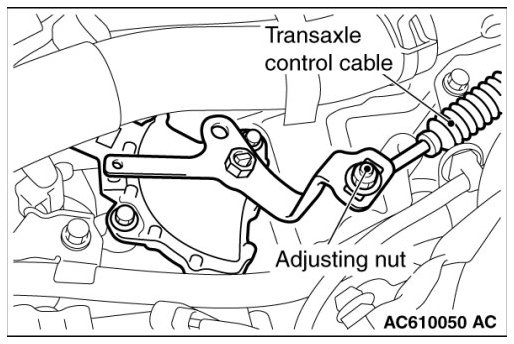
- Improper adjustment of transaxle control cable
- Damaged wiring harness and connectors
- Malfunction of TCM
DIAGNOSIS
STEP 1. Scan tool data list
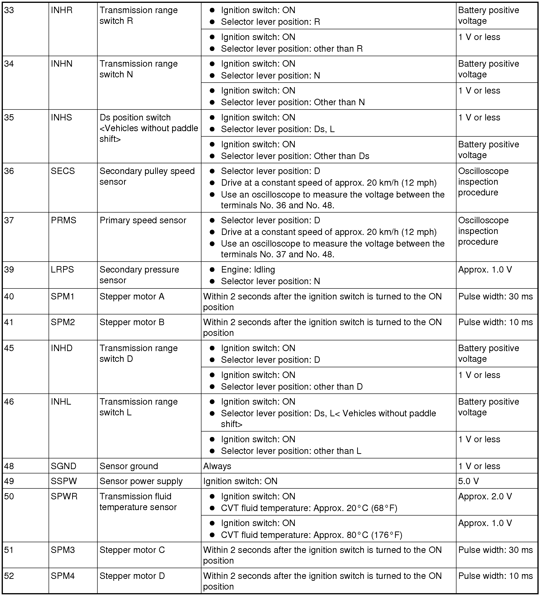
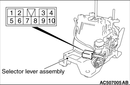
Item 49: Transmission range switch
Check that the service data changes when the selector lever is moved to all ranges.
OK: The service data changes in response to the selector lever operation.
Q. Is the check result normal?
YES Intermittent malfunction
NO Go to Step 2.
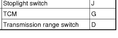
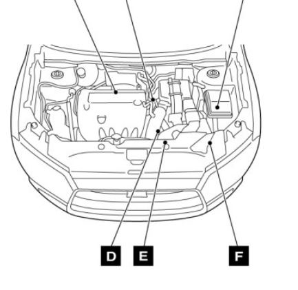
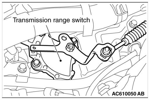
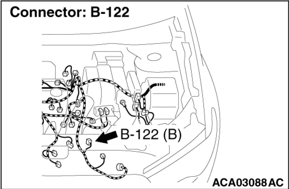
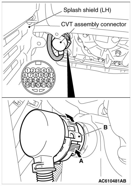
STEP 2. Check the following connector:
- B-122 transmission range switch connector
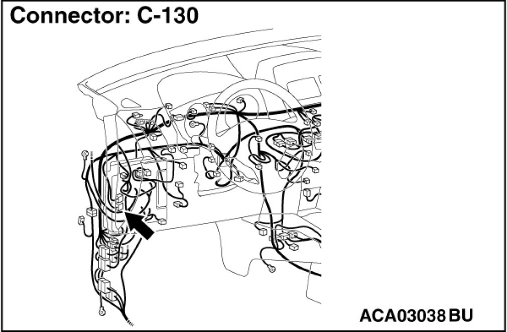
- C-130 TCM connector
Check the terminals for a contact status problem and internal short circuit.
Q. Is the check result normal?
YES Go to Step 3.
NO Repair the defective connector.
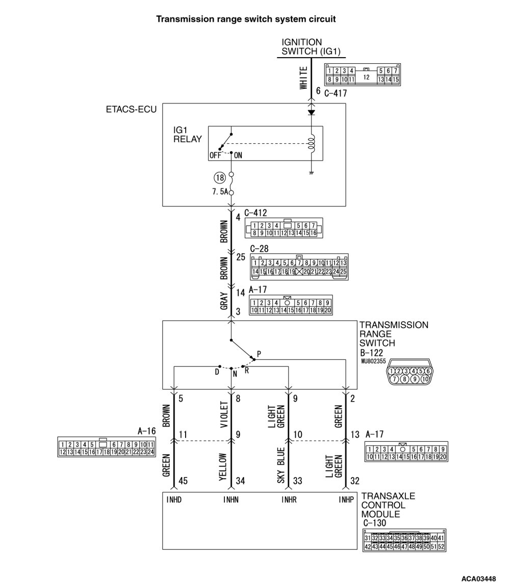
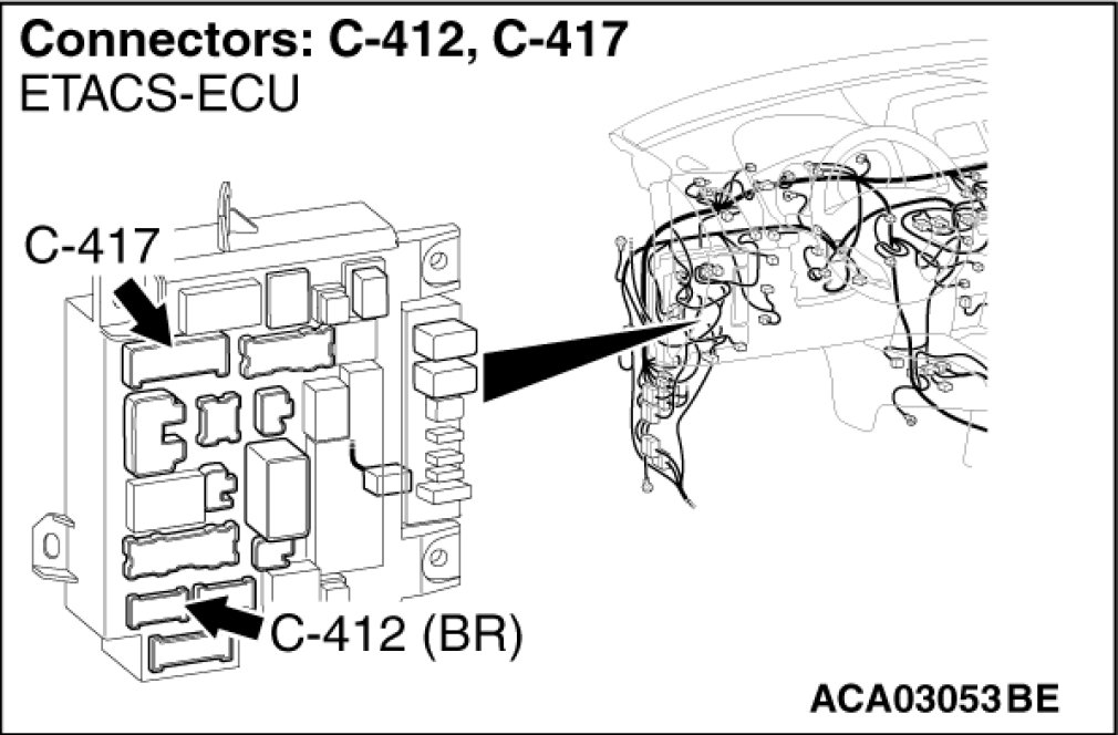
STEP 3. Check for open circuit in wiring harness between the ETACS-ECU connector and the transmission range switch connector
Between the C-412 ETACS-ECU connector (terminal No.4) and the B-122 transmission range switch connector (terminal No.3)
NOTE:
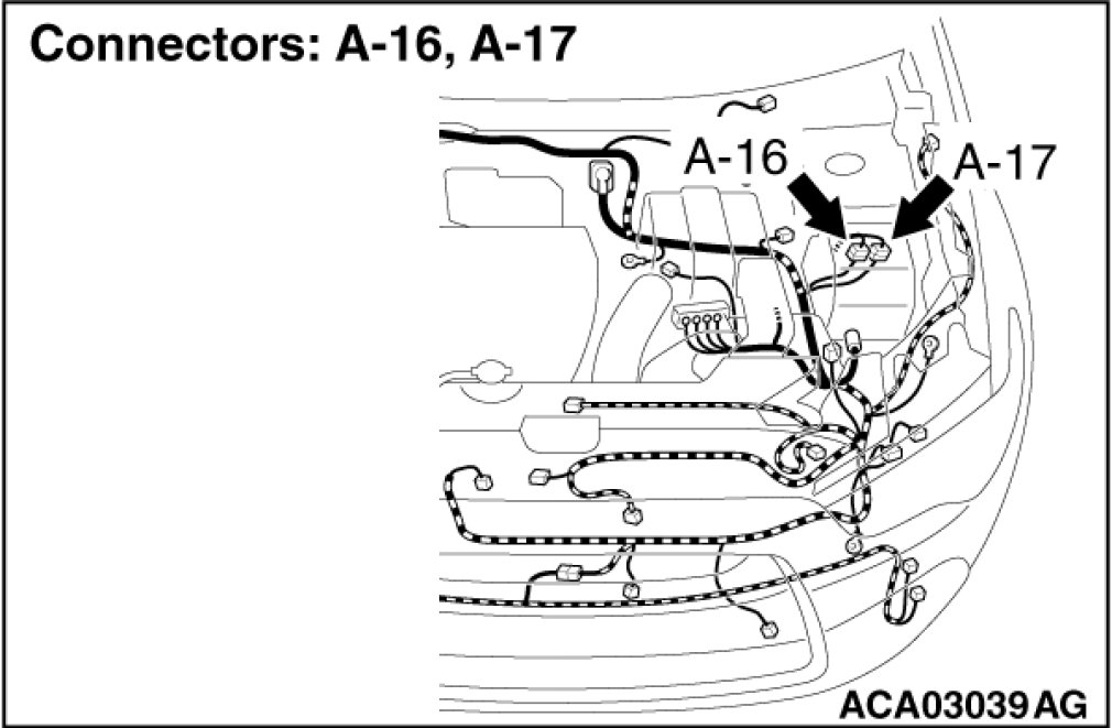
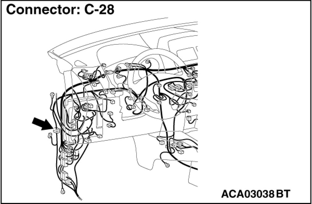
Prior to the wiring harness inspection, check the intermediate connectors C-28 and A-17, and repair that if necessary.
Q. Is the check result normal?
YES Go to Step 4.
NO Repair the wiring harness.
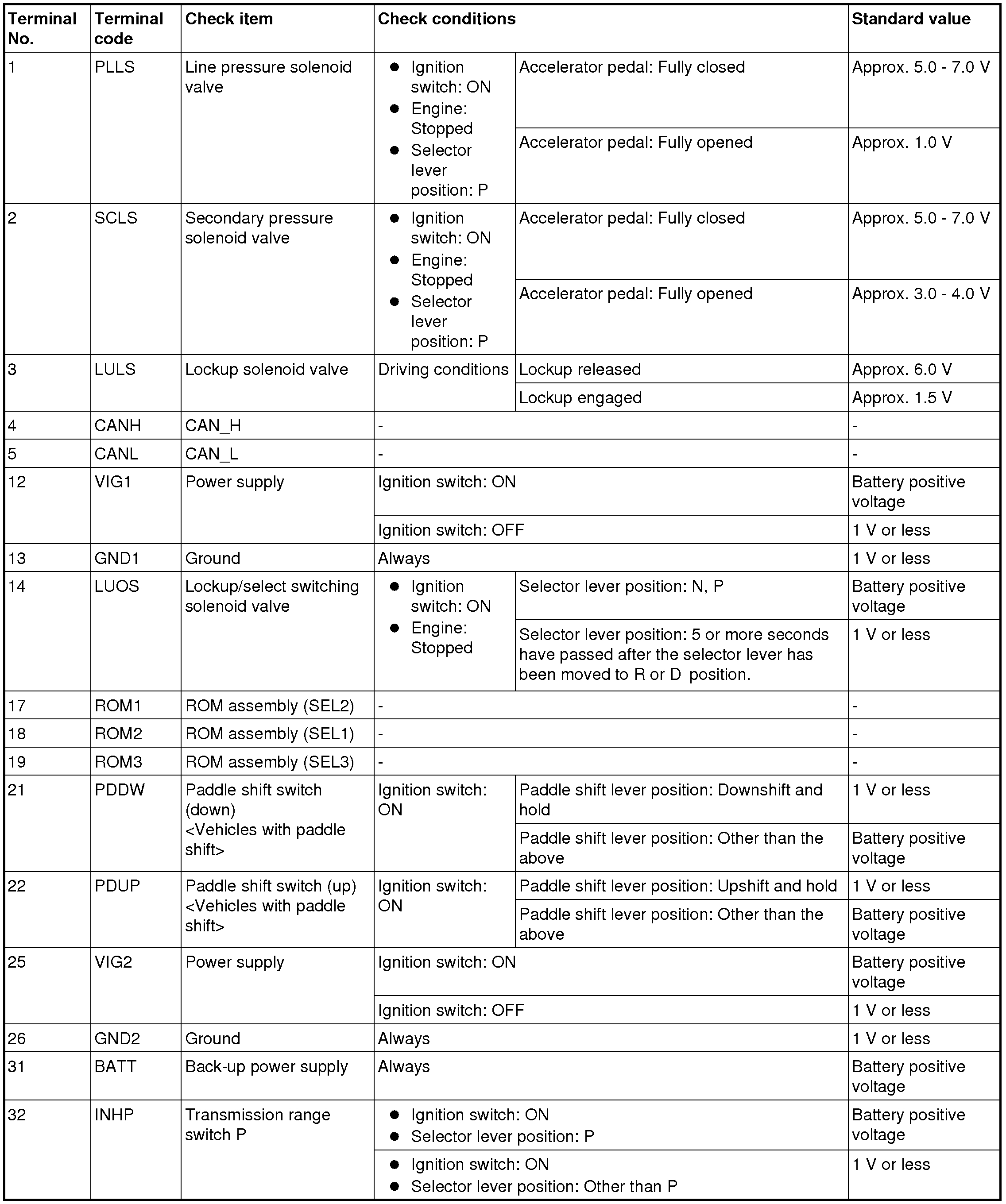
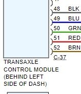
STEP 4. Check for open circuit in the wiring harness between the transmission range switch connector and the TCM connector
- Between B-122 transmission range switch connector (terminal No.2) and C-130 TCM connector (terminal No.32)
- Between B-122 transmission range switch connector (terminal No.5) and C-130 TCM connector (terminal No.45)
- Between B-122 transmission range switch connector (terminal No.8) and C-130 TCM connector (terminal No.34)
- Between B-122 transmission range switch connector (terminal No.9) and C-130 TCM connector (terminal No.33)
NOTE:
Prior to the wiring harness inspection, check the intermediate connectors A-16 and A-17, and repair that if necessary.
Q. Is the check result normal?
YES Go to Step 5.
NO Repair the wiring harness.
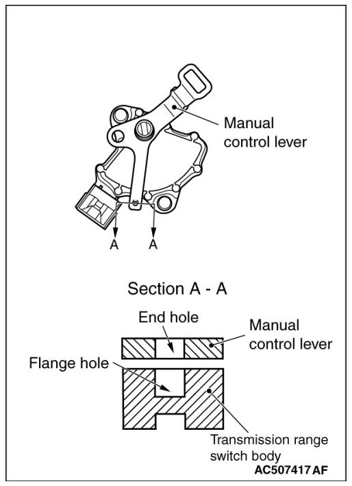
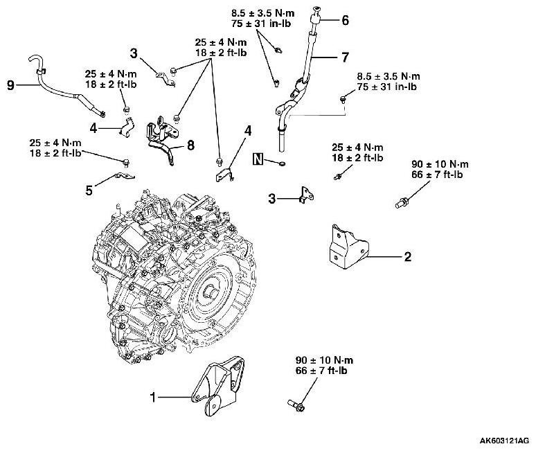
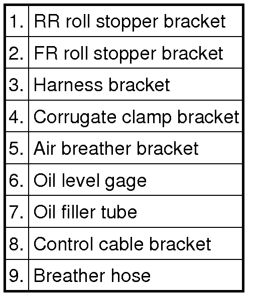
STEP 5. Transmission range switch and control cable adjustment
Refer to See: Transmission Position Sensor/Switch, CVT > Adjustments > Transmission Range Switch and Control Cable Adjustment.
Q. Is the check result normal?
YES Go to Step 6.
NO Adjust the transmission range switch and control cable.
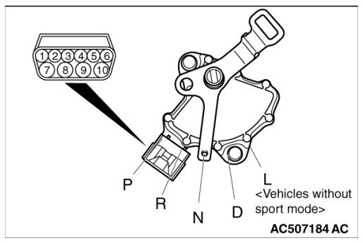
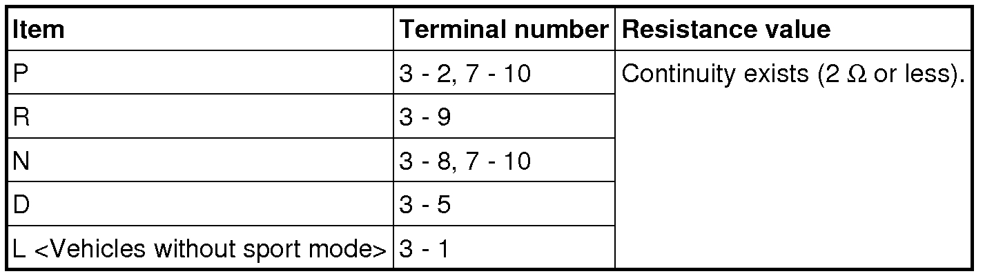
STEP 6. Transmission range switch continuity check
Refer to See: Transmission Position Sensor/Switch, CVT > Procedures > Transmission Range Switch Continuity Check.
Q. Is the check result normal?
YES Go to Step 7.
NO Replace the transmission range switch.
STEP 7. Symptom recheck after erasing diagnostic trouble code
Q. Is the check result normal?
YES Intermittent malfunction
NO Replace TCM.
________________________________
Let me know if this helps.
Take care,
Joe
Images (Click to enlarge)
Mar 20, 2019 at 8:59 PM