Radiator fan stuck on and on high in ignition and with engine running?

2003 MERCEDES BENZ CL55
103,000 MILES • 5.5L • V8 • 2WD
Advertisement
Avatar
SOMEONE12132
  • MEMBER
  • 70 POSTS
I did some more testing with the ECM. It seems that there is proper continuity with the PWM chip on the board from the radiator fan pin. No cracked solders or anything like that as I tested the continuity at the prongs of the chip rather than at the solders itself. I have posted some pictures below showing the things I have tested. I tested a ground on the chip as well, and there is a proper ground on the chip (reads close to 1-2 ohms from the chip to the ground pin on the ecu). I am really confused about what it could be now. Should I check the connector pins itself and see if there is any short to any other pins? Backprobing the wire closer to the ECU reads the same corrupt PWM signal that I was getting earlier.

I would think that if the PWM chip was bad, there would be more major things wrong than just the radiator fan going on full blast, right? But then, again, the PWM signal is not right at all.
Dec 6, 2024 at 12:58 AM
Avatar
AL514
  • CERTIFIED EXPERT
  • 5,464 POSTS
The fan is on high because of the Can bus comms issue, instead of taking the ECM apart scope the bus.
Dec 6, 2024 at 8:38 AM
Advertisement
Avatar
SOMEONE12132
  • MEMBER
  • 70 POSTS
Alright I will. My CAN-bus lines are good as I got a 120-ohm resistance when using a multimeter. Can a faulty CAN-bus signal cause the PWM signal from the ECU to not ground?
Dec 7, 2024 at 8:04 PM
Avatar
SOMEONE12132
  • MEMBER
  • 70 POSTS
Hello again, so I have just found out that my ECU was actually swapped by the previous owner. There are markings on it suggesting that it has been swapped with an ECU off of eBay, or something like that. I'm thinking that the previous owner had the radiator fan issue, but was unable to resolve it with even the new ECU. I'm not entirely sure of this.

Also, I plan on scoping the bus tomorrow. What should I look for when scoping the bus? What can I conclude with such data?
Dec 8, 2024 at 12:53 AM
Avatar
AL514
  • CERTIFIED EXPERT
  • 5,464 POSTS
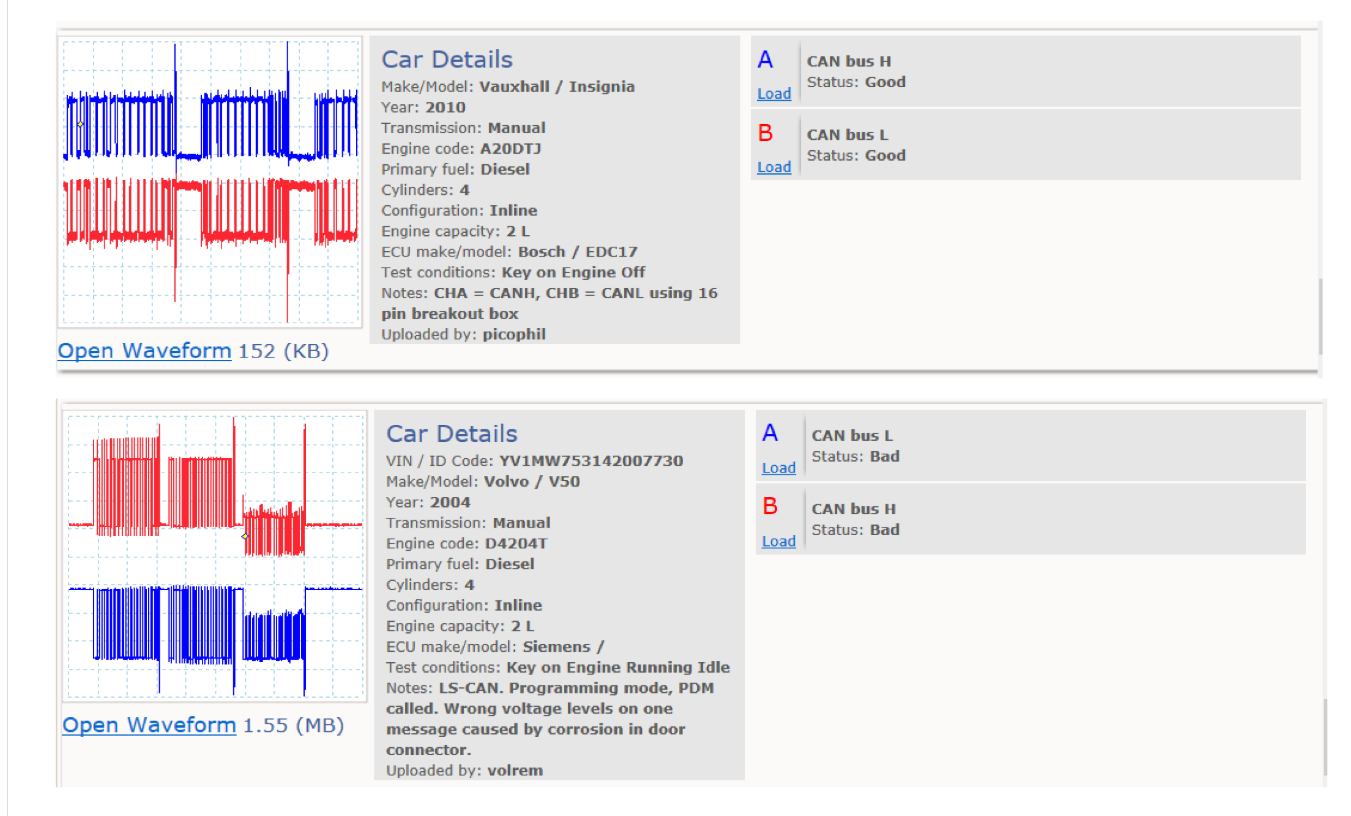
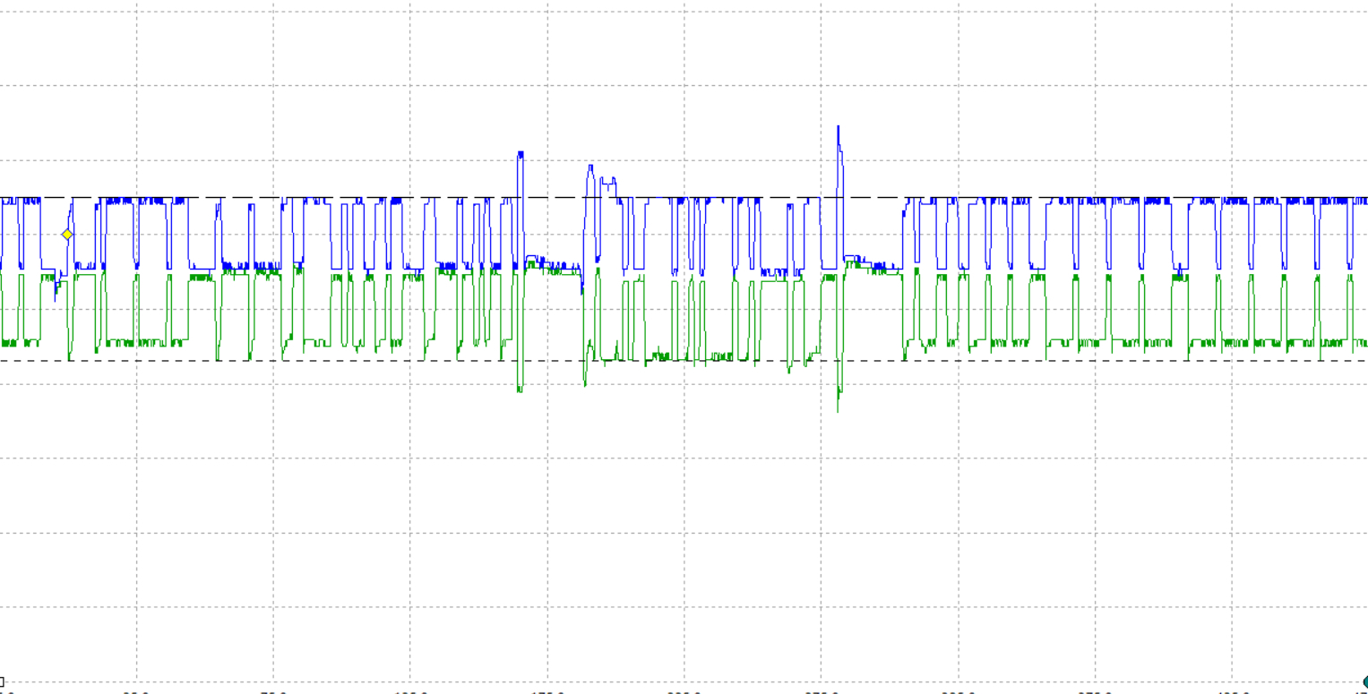
This first example is a known good (upper) and known bad (lower) from the Pico library,
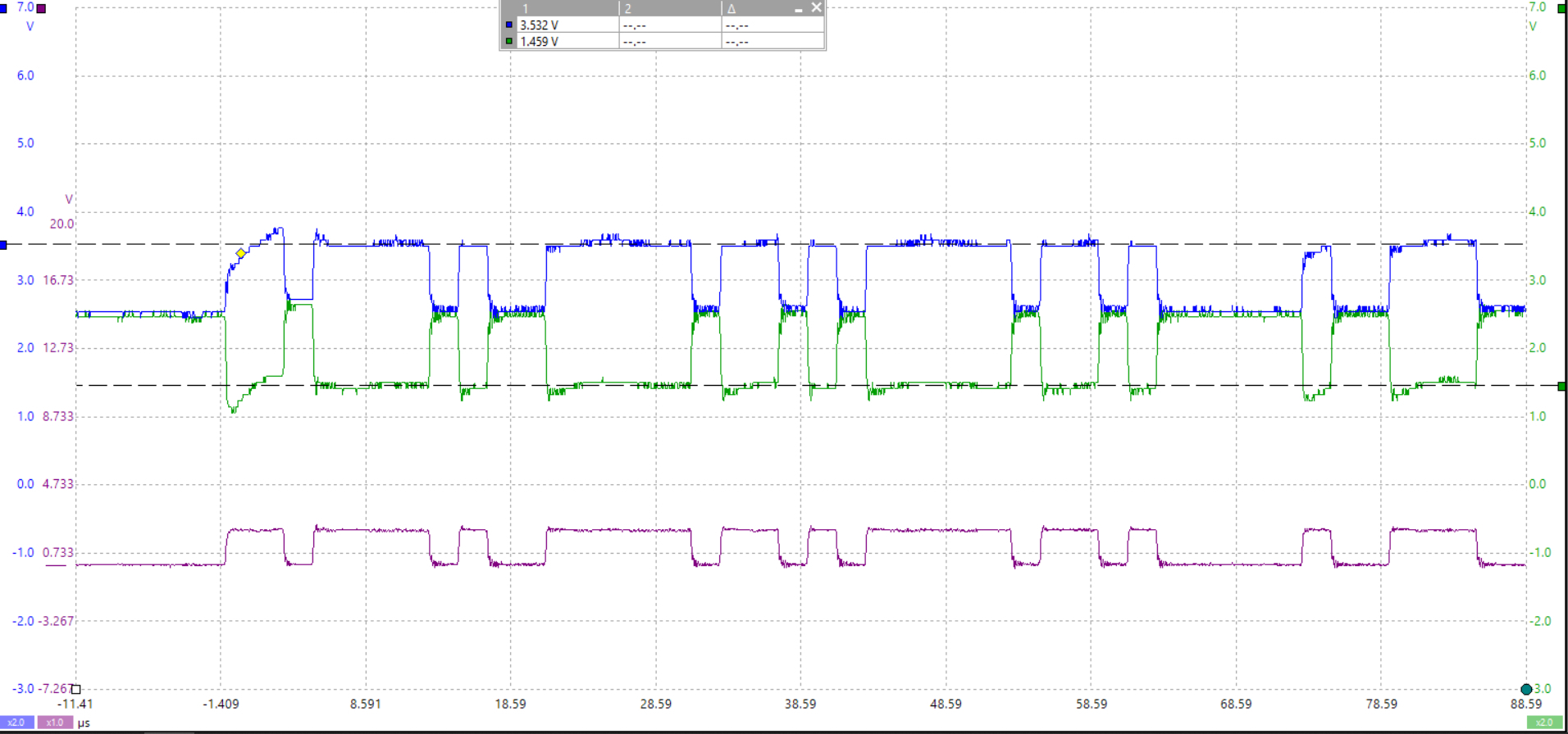
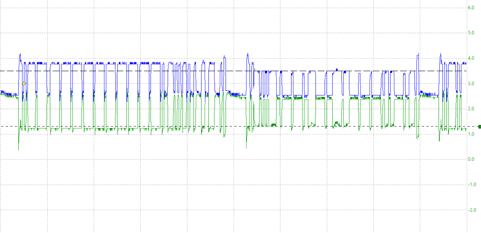
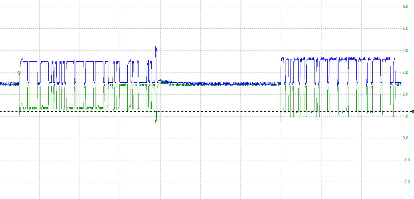
the 2nd one is a vehicle I did some engine work on and noticed some codes setting during my prescan so I scope the bus to see what it looked like, ignore the purple waveform at the bottom, that's a math channel, the Blue is the Can High signal and the green is the Can Low, right off the bat, you can see a sloping waveform, but this is only the beginning section of one message. You can see the same effect in the 3rd waveform.

waveforms 4,5,6 you can see I started to measure the voltage levels of each message packet, this is how you can tell the different modules talking on the network, some modules will have slightly different voltage levels depending on the wiring to that module or the distance from the data link connector, also any possible corrosion in connectors, But Can bus is a very robust 2 wire network and will still be able to transmit even with some wiring issues. Which is why this vehicle still running fine and still does, but it's obvious there's some wiring issues somewhere. In some cases, you will see much more obvious slopes in the waveform, or a waveform that is completely distorted.
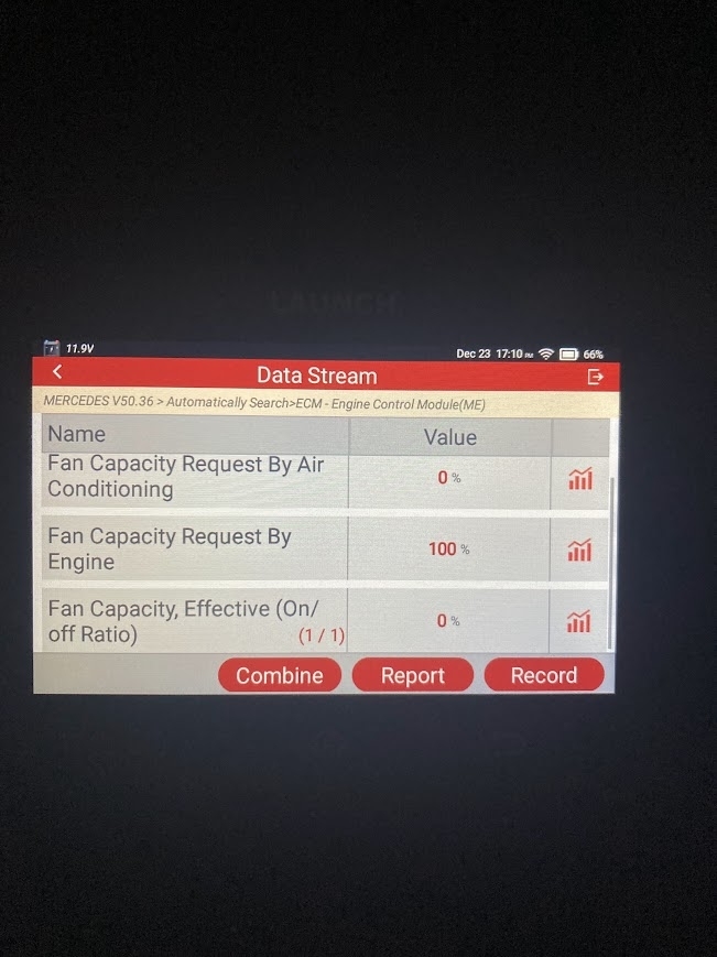
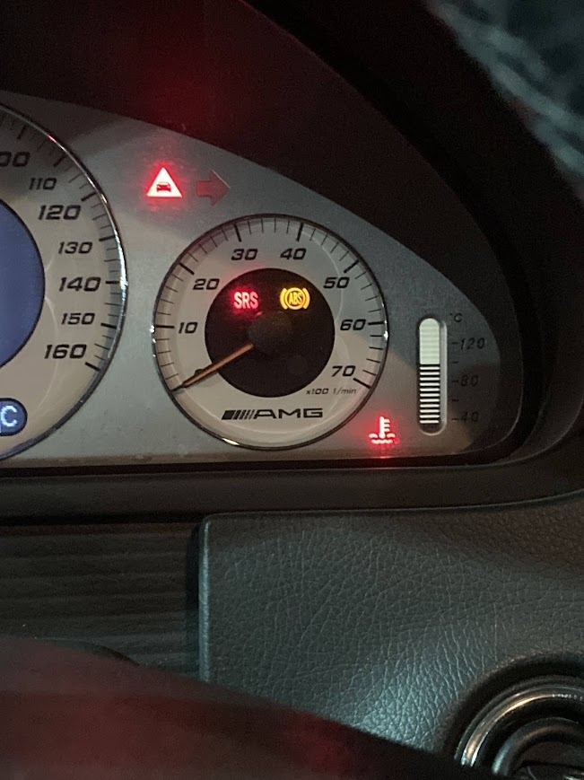
You're getting some communication codes, so some module is not seeing another module on the network that it should be, I don't work on these vehicles because I just don't run into them at all in my area and I do a lot of mobile work, but I have seen these with the fan stuck on high with a no communication issue to the ECM.

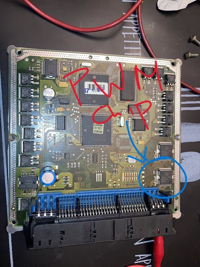
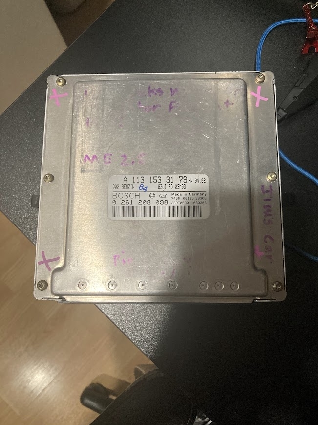
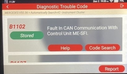
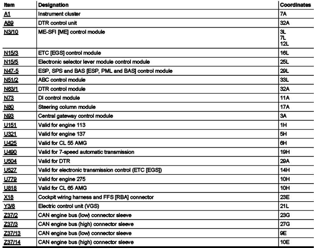
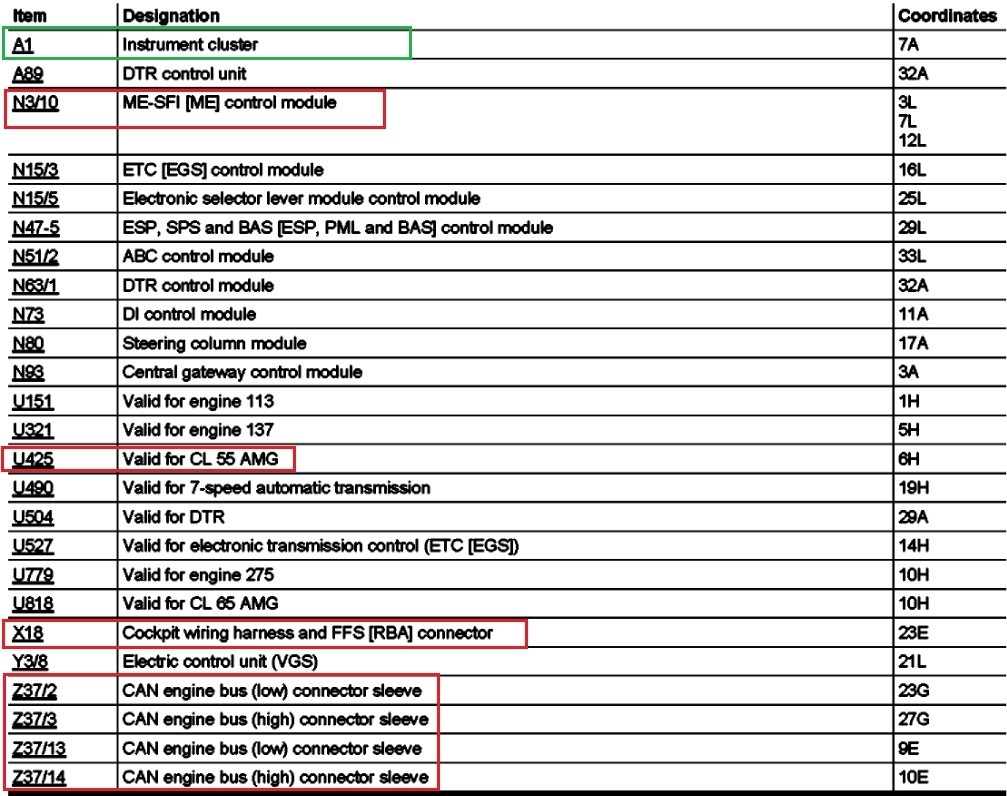
The fact that you may not even have the correct ECM now is going to make things more difficult, but the vehicle runs, this code B1102 (and I don't know if that code number is correct or not) regardless, it's the Instrument Cluster complaining that it cannot communicate with the ECM. It does say if it's a Current or Historic code, but the Instrument Cluster is on the "Engine" Can Bus network along with the ECM (ME-SFI) which makes sense, since it's the Fan running on high that is the complaint right now, but the rest of the communication codes could all be related,
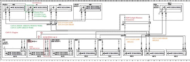
These vehicles have some many modules, diagram 8 is a list of the modules on just the Engine Can network, it might be that the Cluster and ECM cannot talk so the ECM has no way of knowing what the engine temperature might be, and therefore is defaulting the fan to high because of that reason.
What codes come back if you erase them all, (write all the codes down you have right now first) then see what comes back right away. it might take 1 or 2 drive cycles to trip a code,
but you can also go into the Cluster's live data and the ECM's live data with your scan tool and see if there's a difference in ECT data,

If your scan tool shows a network topology, it should show which modules are offline, some scan tools can do that some can't. I think yours show a topology or map of the networks, but these are just plain difficult vehicles to work on if you don't work on them all the time.
Another reason I stay away from them, and BWM, Jag, etc. Ya just end up in these situations that take forever, The Can wires between the Cluster and ECM are supposed to be
Green/White and Green. So, a twisted pair of those two wires will be your engine can bus.
This vehicle is older, so I suspect a wiring issue, water intrusion into connectors is what I find the most.

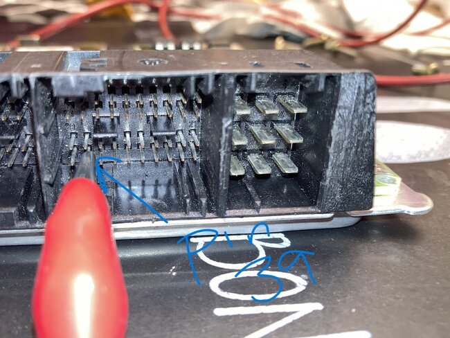
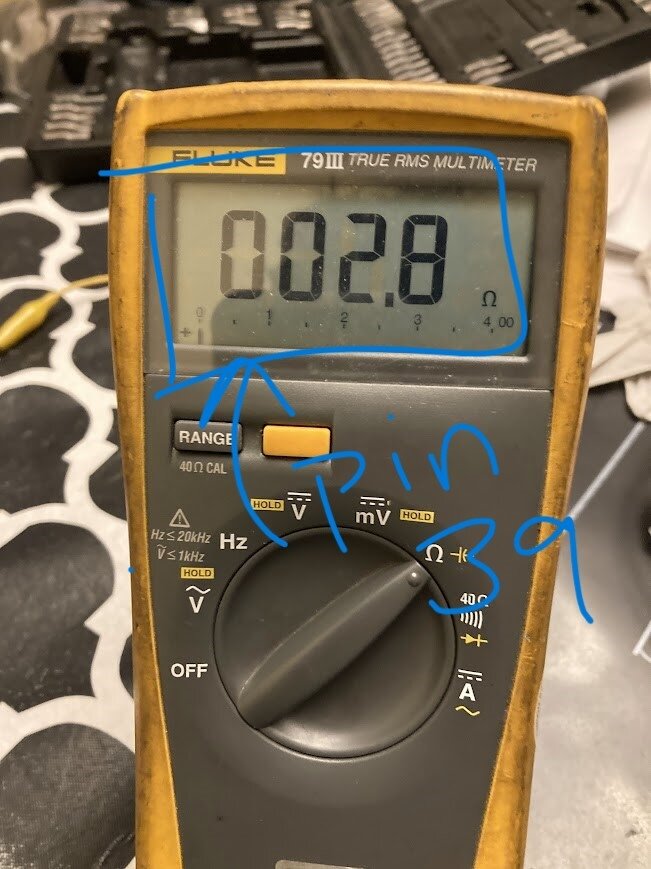
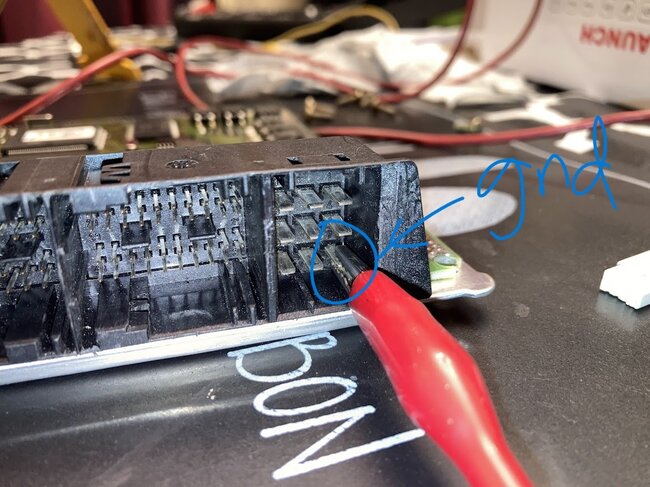
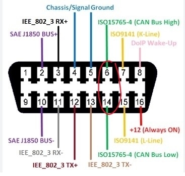
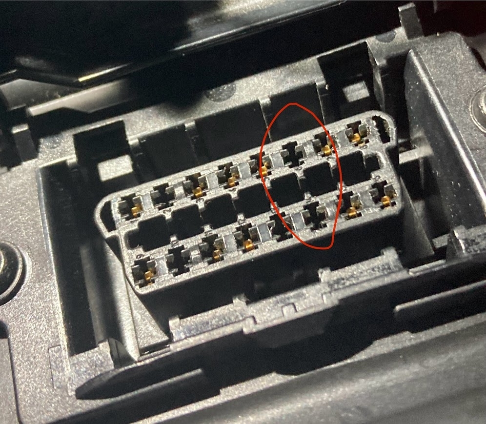
One last thing, your can bus resistance should not be 120 ohms, it should be 60 ohms between Can High and Can Low, so with the key Off, measuring between pins 6 and 14 should read 60 ohms. If you are reading 120 between 6 and 14, then one side of the network is open. You are reading 1 terminating resistor on the network. There should be (2) 120-ohm resistors in Parallel. It's also best to read the resistance of the network with the battery disconnected, stray voltage will change your ohms reading,
If you want me to post the engine bus diagrams I will, but see what codes come back first, and check some easy to access connectors for corrosion, especially ones exposed to the elements.
Sorry for the long post.
Dec 8, 2024 at 12:18 PM
Avatar
SOMEONE12132
  • MEMBER
  • 70 POSTS
I just realized that one of the terminating resistors in the CAN-bus network is in the ECU. The ECU reads 120 ohms as well, which was disconnected when reading this. Additionally, I read the 120 ohms through the pins that connect through the ECU, which is why it gave me that reading. I can conclude that after plugging the ECU back, I should get 60 ohms within the CAN-bus network.

However, I went to probe the CAN-bus signal at my OBD port but noticed that there are no pins for CAN-bus high and CAN-bus low with my OBD port. I've posted pictures below of what I am talking about.
Dec 8, 2024 at 3:37 PM
Avatar
AL514
  • CERTIFIED EXPERT
  • 5,464 POSTS
That is odd, do you see any green/white and green wires twisted in a pair coming out anywhere on the back of the DLC? Or possibly black/white and black twisted pair? I'm seeing different color options on different diagrams here. Component X11/4 is supposed to be the DLC showing pins 6 and 14 being Black/White and Black. Just remember the Can wires should always be a twisted pair, so something to keep an eye out for, but not knowing the complete history on this vehicle, who really knows what has been messed with in the past.
See what you have the back of the DLC and I'll post these diagrams for you.
Dec 9, 2024 at 9:41 AM
Avatar
SOMEONE12132
  • MEMBER
  • 70 POSTS
Okay, I will take a look at the wiring behind the DLC. Also, is it possible that there is a short within the ECU itself that could cause the 3V reference voltage when reading the PWM? Do you also have a list of some sort that shows all the modules on the different CAN bus networks in the car?

Taking a look at the service records of the car, the ECU was replaced by the dealership a while ago.

Also, there is no temperature discrepancies between the ECU and the Instrument Cluster. They both read about the same temperature.
Dec 10, 2024 at 11:17 AM
Avatar
AL514
  • CERTIFIED EXPERT
  • 5,464 POSTS
Yeah, I'll pull everything on that network for you, when you say reference voltage, is this the red wire you're referring to? Or is it a different color wire?
The 4-wire fan harness plug looks like the "Electric Suction fan w/ AC integrated control option". I don't see any other 4 wire options for the fan, service info has the ECM wiring broken up into 2 sections, so I'm having to jump back and forth between the two.

The Cam sensor is a Hall effect sensor that has a 5volt Ref, if it was low, you would have more running issues, and more codes for sensors. It's unclear how many different 5v Ref there are internal to the ECM, but most Reference voltage issues are due to a shorted sensor that shares a ref voltage with other sensors, which will cause a no start condition if it's a critical sensor.
If the vehicle has been to the dealership and had an ECM thrown at it, this problem may have been happening for a long time, and you're just now getting stuck with it. And if a dealership Merc tech couldn't figure out what's going on with this, you know it is a tricky fault.

I'm just going over all the data you've posted so far, I need a refresher really quick.

Dec 10, 2024 at 12:59 PM
Avatar
AL514
  • CERTIFIED EXPERT
  • 5,464 POSTS
Okay, so apparently there are a number of things that can cause the fan to stay on high all the time, many issues, many possibilities, but we know that the ECM is not requesting the fan on, we know that you're getting a code for no comms from the cluster to the ECM, below is a huge diagram of the entire CAN-C network, which is what the code is for, CAN-C.

Diagram 1 is all the modules, and their IDs listed, I've marked the Cluster and ECM for your vehicle.
I suspect a harness issue here, since one or more ECMs have been tried, but if you look at the entire CAN C wires (diagram 2), the Clusters bus wiring has to go through 2 Splices (Z37/13 and 14) Then the wires have to go all the way to the X18 connector, through another Splice (Z37/2 &3) then finally to the ECM.

Hope you like my artwork, anyway, we're not 100% sure other modules on one or the other section of that network are offline, but the wire colors are the same for the entire CAN-C. So, they shouldn't be too hard to find if you pick the ECM or cluster to start with, I'd say the ECM is the easier of the two. The Cluster and the AAC unit communicate on the CAN-B.

I think you're seeing codes for some AC sensors as well, you will probably find a corroded connector somewhere, but notice where the Humidity sensor is located (diagram 6) I think some of the ECMs in these are around that same area, in a plastic box that supposed to have a cover to prevent water from getting in. The back left of the engine compartment, when facing the vehicle is where the Humid sensor is, so you can unplug it and check it as well. Check the ECM harness side connector very well inside for any corrosion or spread pins and take me some pictures so I can see what's up.
The Right Front SAM module supplies power for the fan, or is supposed to anyway, but the command should come from the ECM, so that means the fan is defaulting to high due to a lack of control, I would concentrate more on checking for wiring issues than just scoping the signal to the fan, many vehicles can use known good learned data when there's a networking or module down issue. Keep an eye out for those green/white and green twisted wires, that's your CAN C.
I've read a million reports of different faults causing this same issue, Fan on high with ign On. Find something so we can be special and fix this car.
Dec 10, 2024 at 5:03 PM
Avatar
SOMEONE12132
  • MEMBER
  • 70 POSTS
I'll try to find some fault with the wiring. I'll try to drive the car tomorrow as the computer has been reset from disconnecting the battery to remove the ECU. Just a quick question, could I not be reading any ECU codes because I had previously disconnected the battery when checking the ECU? I remember that I scanned for codes after I disconnected the battery, and did not drive the car.

However, one thing that is important to note is that when checking the ECM connector, there was no corrosion, split pins, or water damage when I inspected it. I can send pictures sometime in the future if you would like.

Also, the connector going to the humidity sensor also has no issues. No water, corrosion, or bent/split pins there either. Likely it's just the sensor that has gone bad.

As for my CAN-lines, I did a resistance test by back-probing the CAN-lines near the ECU rather than at the DLC. It read a 60 ohm reading, like it should. Disconnecting the ECU makes it read 120 ohm (which I assume is due to the other 120 resistor being in the ECU itself).
Dec 10, 2024 at 10:40 PM
Avatar
AL514
  • CERTIFIED EXPERT
  • 5,464 POSTS
With the humidity sensor though, since that and the sun sensor receive a 12volt feed from the AAC module and also share a ground and a connector in series to the AAC, I would check to make sure that 12volts and ground are good. It might be a 12volt reference, but either way with those setting codes, I'd take the time to at least see what's going on with them.
And yes, I'm sure disconnecting the battery erased codes that may have been stored, I don't know if that vehicle has a 2nd battery being that year. So, more codes might set if you take it for at least 2 drive cycles, some codes will take more than one key on drive cycle to set.
Where is the ECM located on the vehicle? is it in the engine compartment on the back passenger side? in a big plastic box?
Dec 11, 2024 at 2:21 PM
Avatar
SOMEONE12132
  • MEMBER
  • 70 POSTS
The ECM is located on the driver's side in the back of the engine compartment (when facing the car). It is in a big plastic box.
Dec 11, 2024 at 3:35 PM
Avatar
SOMEONE12132
  • MEMBER
  • 70 POSTS
Also, just wondering, but I asked a couple of other people for help. Some suggest that the pull-down resistor in the radiator fan has gone bad, or in the ECU. Is the pull-down resistor with this fan signal in the ECU or in the fan module? How can I go about checking this?

Additionally, I'm not sure if I am repeating myself here, but when I scoped the radiator fan line, it was with the harness disconnected from the fan. I'm not sure if this can affect how the PWM signal looks.
Dec 11, 2024 at 3:45 PM
Avatar
AL514
  • CERTIFIED EXPERT
  • 5,464 POSTS
I dont know what kind of resistors are in the fan module, pull down or up circuits are usually for position sensors, plus theres the bulletin on a different harness for the fan, but you said the ECM has been replaced, if the fan is running unplugged the harness then its running on its default fast speed because theres no control from the ECM.

The fan operations states, "The AAC control and operating Unit transmits the status of the air conditioning via the CAN data bus to the ME control unit. The Fan specified speed is dependent on this and on the coolant temperature".
But obviously there is no control to it or the ECM (ME) would be reading a percentage but its not.
Im not a Merc Benz engineer though, I cant tell you how they build their modules. Especially from 2003. I wouldnt read into the waveform too much, you dont know whats a known good signal looks like, Id think it would be pulling fully to ground as well, but with Data bus codes, you could replace the fan, ECM, and who knows what else and still have the same problem if its a wiring issue. There could be a connector somewhere thats full of corrosion, I assume there is a main power wire going to the fan if its running with the harness disconnected? Wheres the power coming from?
Dec 11, 2024 at 7:44 PM
Avatar
SOMEONE12132
  • MEMBER
  • 70 POSTS
The power is coming from a 12V that I believe has a fuse, which then goes to the battery. This is always on, as it should be.

The PWM signal controls the mofset in the radiator fan. The signal does need to ground out between each pulse to ensure that the fan is in the "off state".

I do have data of what a good signal is like: https://w220.wiki/Engine_fan
The w220 uses the same fan design the CLK 55 AMG uses. They have listed how the PWM signals should look like.

Also, I am unsure if the ECU has been replaced. It could be replaced. It has definitely been inspected/tampered with in the past, most likely because of this issue.

Someone did suggest running a resistor in parallel to the signal line to ground to pull down the signal, but of course this didn't work.

Right now, I am suspecting the chip to have gone bad.
Dec 14, 2024 at 12:06 AM
Avatar
AL514
  • CERTIFIED EXPERT
  • 5,464 POSTS
Yeah, there would have to be a power mosfet on the feed or ground to control the fan, that's why I had asked awhile back if that signal wire was shorted to a 5v ref, but then you stated it was actually only 3.8v, on any power circuit that I've ever designed that used a mosfet I've always had a 10k resistor between the Source and Gate of the FET, these are usually almost always only 5 or 12v circuits, but it depends on the size of the resistor too, this 10K helps to pull the FET fully to ground, but it is only a 1/4watt resistor as well, something like a fan is going to pull amps.
You could do a resistance check from the signal wire to the ECM and see if its either shorted to ground or an open circuit, so measuring starting on the fan wire since you already know which one that is, measure from the wire to ground for continuity, if its ok, no reading (OL) then measure from the fan to the ECM and see if that reads OL, it shouldn't, it should be less than 5ohms if the wire is complete. And actually, you should get the same waveform at the ECM wire that you're seeing at the fan. If it's not an open wire you would see the same waveform at the ECM. If so, you could cut the wire or de-pin it and see what happens to the fan, my guess is that the fan might stay high. Being that it's supposed to be a 12v signal as you looked up, that lack of voltage on the signal wire is the reason its most likely defaulted to high speed. Calling a bad ECM or any module for that matter is always a difficult call. But I would see what kind of signal is coming out of the ECM. If there's a 12v signal you know the wire is probably corroded (resistance) between the fan and ECM, and hence the low voltage.
The only connection on the wiring diagrams between the fan and ECM is the Right Front fuse and relay module, which I believe is the Right front SAM module.
Dec 14, 2024 at 1:40 PM
Avatar
AL514
  • CERTIFIED EXPERT
  • 5,464 POSTS
I stand corrected, the Right Front SAM module is labelled as N10/7 and the Right Front fuse and relay module is labelled K40/7, so it's not a SAM control module, but the wiring for the fan does go through that Right Front fuse module, after the fan, for some reason they run the control wire of the fan into and out of the Fuse/relay module, I'm never sure why they do that if it really has no effect on the circuit. I think engineers like to make things more confusing than necessary.
Dec 14, 2024 at 1:45 PM
Avatar
AL514
  • CERTIFIED EXPERT
  • 5,464 POSTS
This wire I highlighted in green is the control wire coming from M4/7 (fan). I don't know if that's correct with this specific vehicle, because there are changes in design about halfway through 2002 when this vehicle would be in production.
If that fan cover comes off with a few bolts or screws, you could take the cover off and look for a broken or burnt solder joint. I find plenty of broken solder joints that's for sure.
Dec 14, 2024 at 1:52 PM
Avatar
SOMEONE12132
  • MEMBER
  • 70 POSTS
With the harness unplugged, reading continuity from the signal wire to ground reveals 100kOhms of resistance. I feel like this is logically correct as a PWM signal requires a pull down resistor to pull the signal down to ground.
Dec 14, 2024 at 6:05 PM
Avatar
SOMEONE12132
  • MEMBER
  • 70 POSTS
The diagram is also correct, it is a green wire that goes through a fuse box into pin 39 of the ECU.

I really hope this is not a bad ECU, because an ECU is pretty expensive in the first place, let alone on a Mercedes of all things. Additionally, programming the ECU to work with the other systems on-board, such as the EIS, will also cost lots of a money.

I would replace the chip itself, but that specific part number is not sold anywhere, and you cannot buy the chip itself from Bosch/Mercedes as they gatekeep it.
Dec 14, 2024 at 6:11 PM
Avatar
SOMEONE12132
  • MEMBER
  • 70 POSTS
Also, I believe there is something wrong with the on/off ratio. I believe that the on/off ratio should be 10% for the fan to be off. Anything less than 5% would trigger the fan to stay on. Not sure why my on/off ratio for the fan is at 0%.

I got this information from this video: https://www.youtube.com/watch?v=1pfIXvp-2DE&ab_channel=jroncallo

He uses a fan from a Mercedes of the same year/generation, which all shared the same type of PWM signal.
Dec 14, 2024 at 11:14 PM
Avatar
AL514
  • CERTIFIED EXPERT
  • 5,464 POSTS
It may not be reading anything from the ECM side if its ignoring the fan or due to a communications fault. If the ECM is not able to communicate with part of the AC system or the other way around, many fans will default to high because of that. Other manufacturers do the same thing. If theres a loss of comms with the ECM and the vehicle still runs for whatever reason they default the fan to high to prevent over heating to the engine, when engine temperature cannot be monitored correctly. From what Ive seen that seems to be the case and its a logical answer, its better to have an engine run a little cooler than over heat so they just blast the fan on high all the time. But yes a computer for this Im sure is expensive. I would try a used fan first and see theres any difference. 100K to ground might be ok, considering its a signal wire. I dont think that wire is meant to carry current, it seems more like how a fuel pump module receives commands with a 12v duty cycle signal. Have you scoped the network to see if theres any distorted looking waveforms, everything should be pretty square with that Can bus, dont dismiss the network fault codes, what if you replace the ECM and still have the same issue, most places wont take a used module back.
Dec 15, 2024 at 11:37 AM
Avatar
SOMEONE12132
  • MEMBER
  • 70 POSTS
Here's what I did to test if everything is working. I disconnected the temperature sensor and kept the car in ignition. The PWM signal remained the same (the 3.5V-3.8V) peak-to-peak at 10hz with a 10% duty cycle. No changes there, even though it should be requesting the fans to be at full blast. Perhaps I can rule it as being the ECU here, as the ECU is not doing anything to change the radiator fan signal. It just seems fixed.

I haven't been able to scope the network at all because the OBD port doesn't have a pin connecting to the CAN bus high/low. There are no twisted wires where the OBD port connects, so I am not sure how I can check the signal.
Dec 15, 2024 at 4:50 PM
Avatar
AL514
  • CERTIFIED EXPERT
  • 5,464 POSTS
You should be able to see on your scan data the engine temperature sensor change to an open circuit number, usually a temp sensor defaults to -40f degrees when unplugged, and you could back probe the ECM connector to see what the Bus looks like there.
Pin 1 green/white wire (CAN-C High) and pin 11 green wire (CAN-C Low) (twisted pair), if you have only a 2 channel scope you can go across those 2 pins and should see a bias voltage of 2.5volts, which is what the Can signal rides on. Can High should go from 2.5v to 3.5v and Can Low should be 2.5v down to 1.5v. Really youre looking for any weird sloping lines in the network signals, I like to take a first capture of a longer time base, that way I can see the very slight differences in each message packet, which is something you will notice. Each packet wont be exactly 3.5v up for example, but the slight differences are different modules communicating on the network. Its not easy by any means, I understand fully of not being 100% sure of what you might be looking at, I cant tell, just by a weird waveform, what the fault is, but when a square wave just doesnt look right you'll notice it, especially since youre a scope user which is really great. Not enough techs use them, I try to use for anything possible. If you have a good running vehicle around, take a look at its can bus so you can see what a good signal looks like. You can do a lot with just a 2 channel scope.
I was wondering if that signal changes at all with the ECM plugged in, does the scope capture have any change at all.
Dec 16, 2024 at 8:40 AM
Avatar
SOMEONE12132
  • MEMBER
  • 70 POSTS
Hey, so it seems that I have resolved the problem. It indeed was the ECU!

There is a Bosch 30344 chip that this radiator fan signal comes from on the ECU, and this chip seemed to be shorted/broken, which caused this corrupt PWM signal. I took a chip from another Mercedes with a ME 2.8 board, and swapped it onto my car, and it worked.

The PWM signal looks proper now, and the radiator fan doesn't go on full blast as soon as the car is put into ignition.

Thank you so much for the help, and hope you have a great rest of your holidays!
Dec 20, 2024 at 11:06 PM
Avatar
SOMEONE12132
  • MEMBER
  • 70 POSTS
Hello,

I'm currently suffering with a problem with my CLK where the radiator fan will not come on when the engine requests for the radiator fan.

I was able to determine this by disconnecting my temperature sensor, which forces the ECU to request the radiator fan to run at 100% as a safety measure.

I ran an actuation test of my radiator fan, and I was able to turn on the radiator fan this way. This means my radiator fan is probably fine, and perhaps my ECU as well.

I am more concerned about my radiator fan not running when my engine is requesting it to be on. It is causing my car to overheat in traffic. I'm not sure what it could be.

Note: Car was in ignition when performing all these tests.
Mar 4, 2025 at 1:58 PM (Merged)
Avatar
AL514
  • CERTIFIED EXPERT
  • 5,464 POSTS
Hello, I thought you had this all sorted out already?
Mar 4, 2025 at 1:58 PM (Merged)
Avatar
SOMEONE12132
  • MEMBER
  • 70 POSTS
I thought I had, but there is something else wrong with this car.

Alright, so I did do some checks, and the radiator fan does come on when the engine does request for it. Unplugging the coolant temperature sensor and turning on the engine makes the engine request the fan at 100%, and the fan does indeed come on at full blast, so we can rule out the radiator fan being an issue here.

I'm not sure if this is the proper temperature for stop-and-go traffic, or if it is overheating. This is the max temperature it goes to in stop-and-go traffic, but it does go down once on the highway.

Maybe something else besides the radiator fan is wrong here as this has been tested already? What could I check for?
Mar 4, 2025 at 1:58 PM (Merged)
Avatar
AL514
  • CERTIFIED EXPERT
  • 5,464 POSTS
I assume you've cleared out all the codes after the last repair, what's the ECT getting to in the stop and go traffic (we'll call it city driving). It looks like 100c on the Cluster, so roughly 212f? Is that accurate to scan data? and are codes setting after 2 drive cycles?
Mar 4, 2025 at 1:58 PM (Merged)
Avatar
AL514
  • CERTIFIED EXPERT
  • 5,464 POSTS
These are the two coolant system diagrams, pretty complicated thermostat setup, Mode F shows coolant temp greater than 102c, thermostat fully opens to flow through the radiator. So that would be its max temperature unless I can find a different spec.
Mar 4, 2025 at 1:58 PM (Merged)
Avatar
SOMEONE12132
  • MEMBER
  • 70 POSTS
Hello,

Recently on this website, I had a problem with my radiator fan running at full speed due to a chip in the ECU being faulty. I had replaced this chip in the ECU with a new one, which made the problem go away, at least for a couple of months.

The way the ECU communicates to the radiator fan is through a signal wire directly connected to the ECU, where a PWM signal is sent from the ECU to the radiator fan module to determine the fan speed.

The problem came back again, where the chip was blown again, causing the radiator fan to run at full speed. Could there be a bigger problem with the ECU itself, or could there be a problem with the radiator fan module sending some sort of back-charge through the signal wire, inherently frying the chip in the ECU?

Note: I know I have listed my car as a CL55 because the website doesn't include a CLK55. This is specifically for a CLK55.

Here's also the link to the forum post addressing this chip issue: https://www.2carpros.com/questions/radiator-fan-stuck-on-and-on-high-in-ignition-and-with-engine#last
Mar 4, 2025 at 1:58 PM (Merged)
Avatar
AL514
  • CERTIFIED EXPERT
  • 5,464 POSTS
There are some pretty interesting info, along with the ton of other information on the cooling system, but I'm not sure what the water to antifreeze ratio is right now in the vehicle, but they have a very specific ratio spec and some reasoning behind it, if its 55% or more antifreeze, apparently this increases the boiling point of the mixture due to lower heat transfer of the coolant itself. So really it should be a 45% antifreeze ratio that will bring it to -22f freeze protection, But if there is a much higher ratio of antifreeze, which is difficult to tell unless its checked, who knows if the customer has just been dumping straight antifreeze in it over the years and the percentage is much higher now, you could check the concentration with one of those floating ball gauges, but it says to only use MB antifreeze as well. Not something that's well known I'll bet, about the boiling point changing according to the mixture. Regular people usually just dump in whatever is in their garage.
Mar 4, 2025 at 1:58 PM (Merged)
Avatar
SOMEONE12132
  • MEMBER
  • 70 POSTS
Just curious, should the antifreeze be a green color? That is what is currently in my car right now.

After 2 drive-cycles, there were no codes at all.

I need to check the ECT data when the car is up to temperatures, which I will do sometime soon.
Mar 4, 2025 at 1:58 PM (Merged)
Avatar
AL514
  • CERTIFIED EXPERT
  • 5,464 POSTS
I'm not sure what color the MB coolant is, the green coolant is most likely just regular old antifreeze, but is the 100c temperature the highest it's getting on the gauge?
Mar 4, 2025 at 1:58 PM (Merged)
Avatar
SOMEONE12132
  • MEMBER
  • 70 POSTS
Yes, 100C is the highest it gets on the gauge.
Mar 4, 2025 at 1:58 PM (Merged)
Avatar
SOMEONE12132
  • MEMBER
  • 70 POSTS
So, I managed to recreate the same situation again, and here are the results.

Radiator fan turns on when the coolant temperature is at 97C. The radiator fan is doing its job, and the coolant temperature goes back to 92C when at a stop. At 92C, the radiator fan is off. It never exceeds that 97C, so I'm hoping that means that means everything is good with the radiator fan?

From what I see, it seems that the gauge is off by 5 degrees C, so I'm pretty sure there is nothing to worry about for now.

However, is that range of 92C to 97C normal operating temperature, or is it too hot?
Mar 4, 2025 at 1:59 PM (Merged)
Avatar
AL514
  • CERTIFIED EXPERT
  • 5,464 POSTS
well ,92c is only 197.6f, 97c is 206.6f, and on either coolant system diagram 102c is when the thermostat is fully opened and coolant is directed through the radiator,, the 206f is okay with me, I know that a Subaru kicks on the cooling fan at exactly 204f because I used to work for them at a dealership. But remember that you did have a communications code from the Cluster to the ECM at one point, I'm not sure how much of the harness you have messed with since then, what's been unplugged and plugged back in, but I'm sure you would get a warning light on if the coolant temperature went too high. I know the temperature in Celsius can look foreign to us techs in the US, I usually just google a Celsius temperature to Fahrenheit, and it will bring up a conversion chart, it's just easier for me to see it that way as well.
Mar 4, 2025 at 1:59 PM (Merged)
Avatar
AL514
  • CERTIFIED EXPERT
  • 5,464 POSTS
I would drive it for a couple days and take a few longer drives to see if any codes are set, some take longer than others, but it looks like you're getting to the bottom of things finally with this vehicle.
Mar 4, 2025 at 1:59 PM (Merged)
Avatar
SOMEONE12132
  • MEMBER
  • 70 POSTS
There were no codes that were set. I drove it many times on the highway, went through stop-and-go traffic, drove it through the city, and even drove it through the backroads. Also, I believe I said that there's green coolant in it, but I was mistaken. There is actually the proper blue coolant in the cooling system.
Mar 4, 2025 at 1:59 PM (Merged)