Radiator fan stuck on and on high in ignition and with engine running?

2003 MERCEDES BENZ CL55
103,000 MILES • 5.5L • V8 • 2WD
Avatar
SOMEONE12132
  • MEMBER
  • 70 POSTS
Hello,

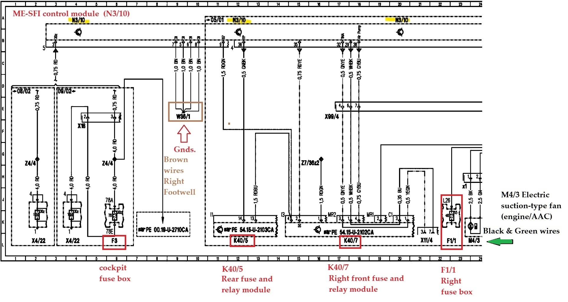
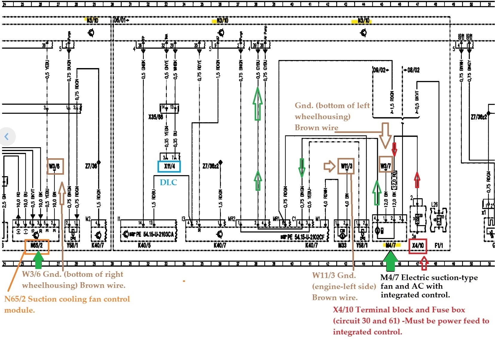
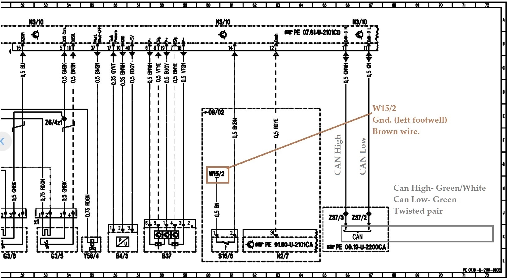
I’m currently having a problem with my car where the radiator fan is on full blast when the car is in ignition and the engine is running. Here’s what I’ve checked so far:

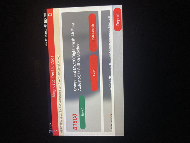
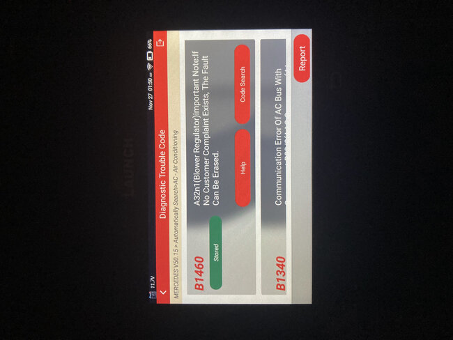
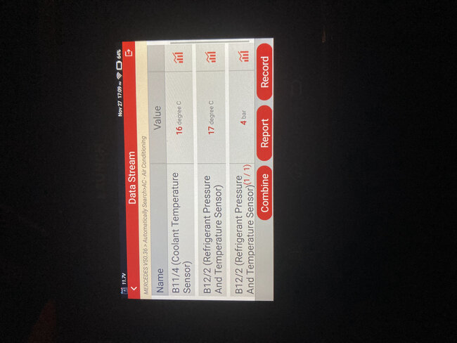
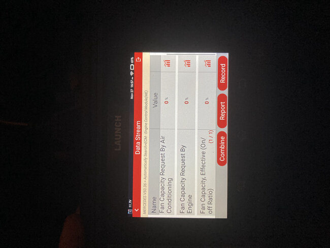
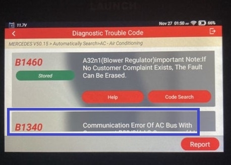
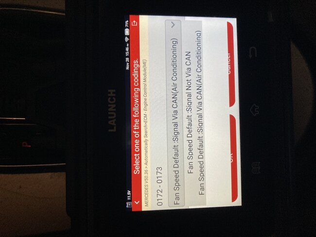
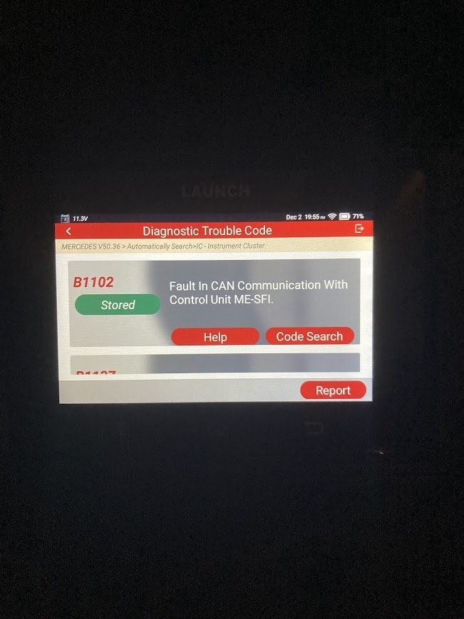
I’ve checked for codes from the ECM and Front SAM module. No codes there. I’m using a Launch X431 to check for these codes.

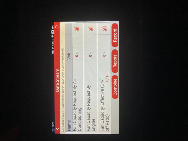
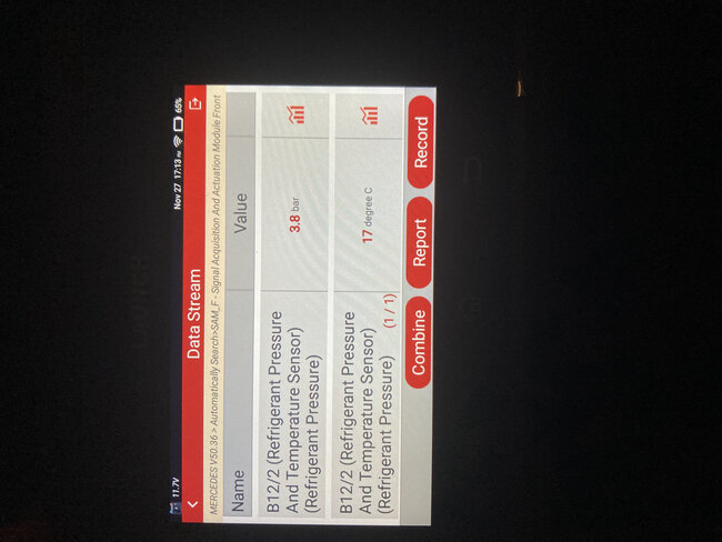
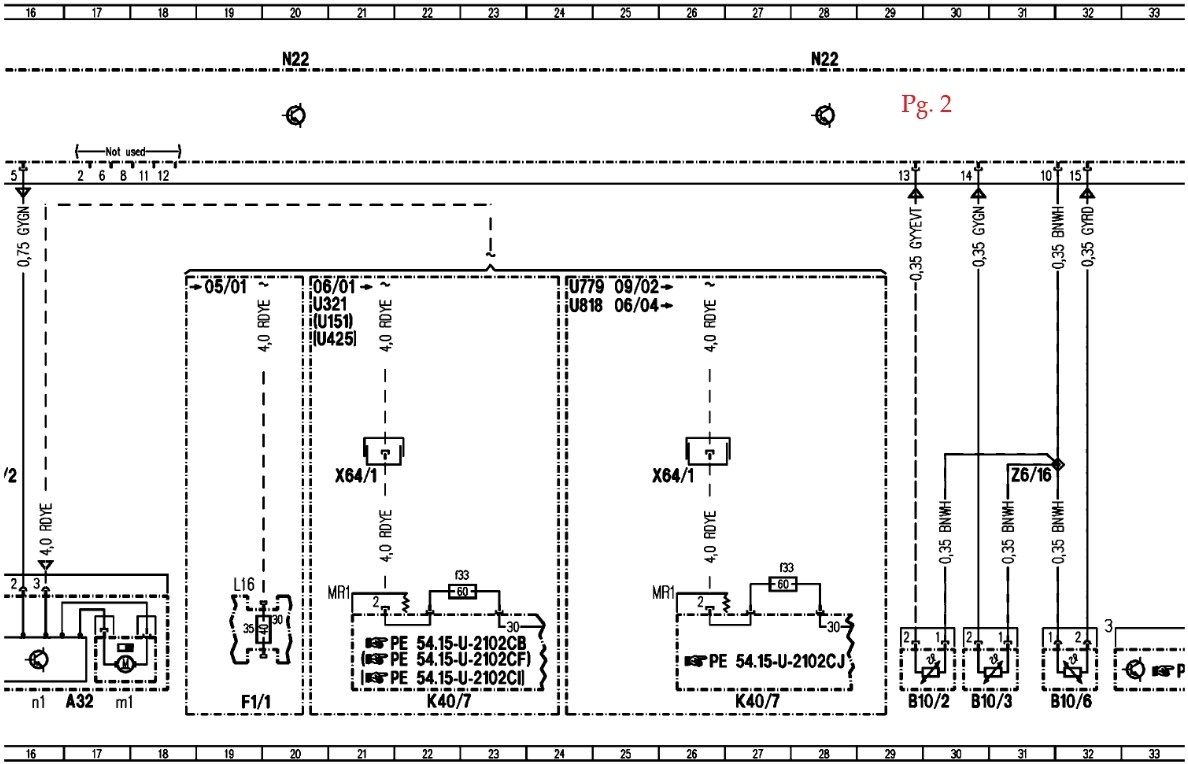
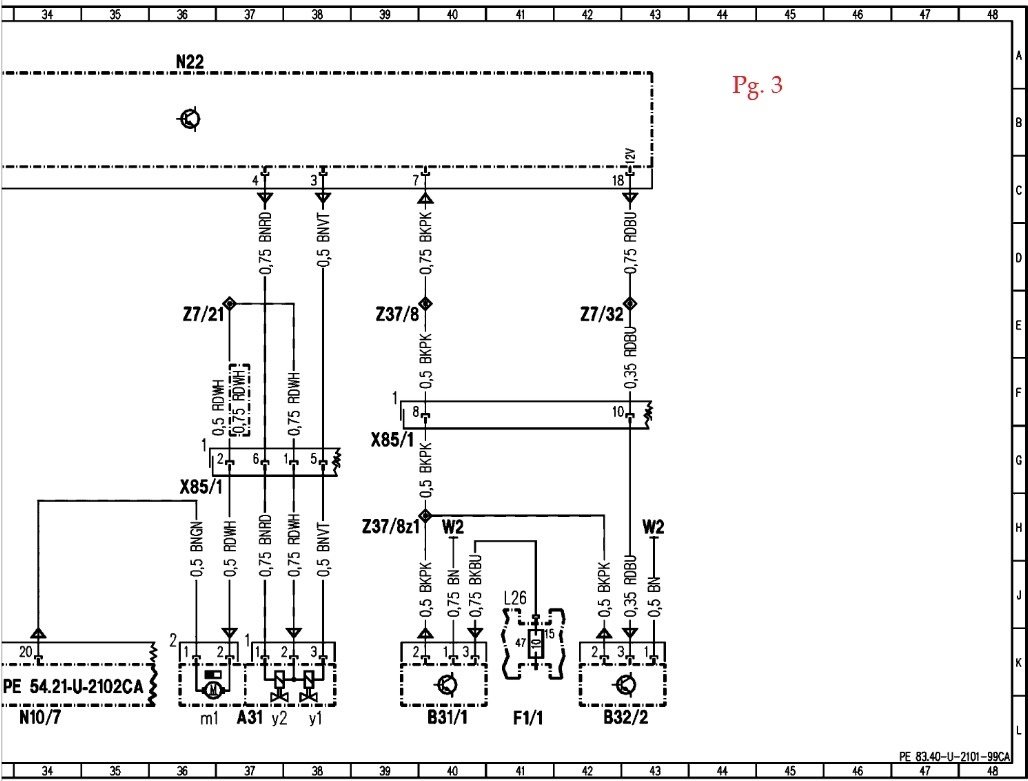
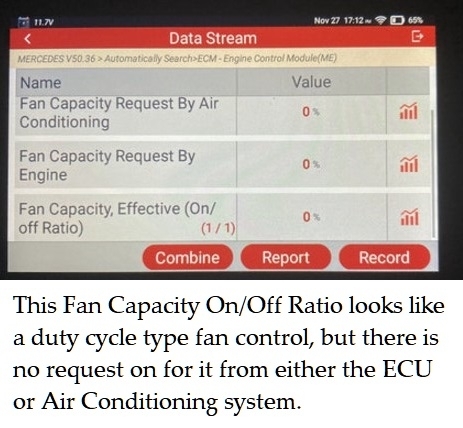
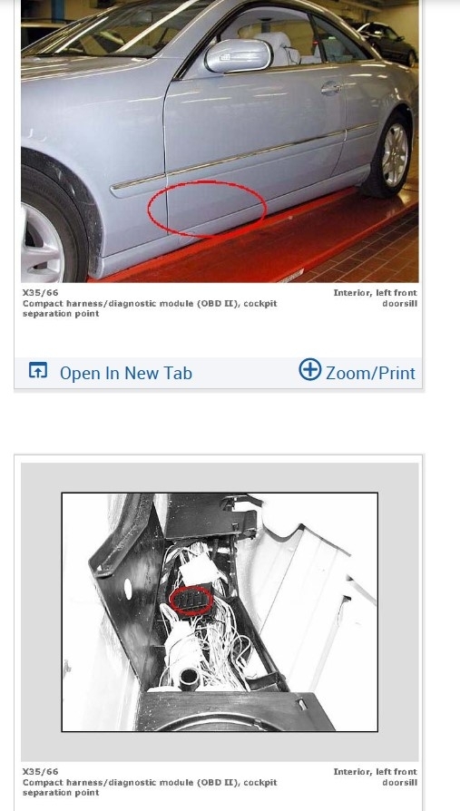
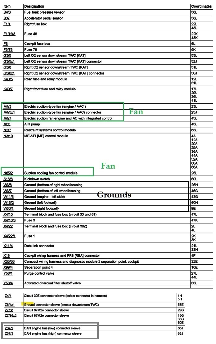
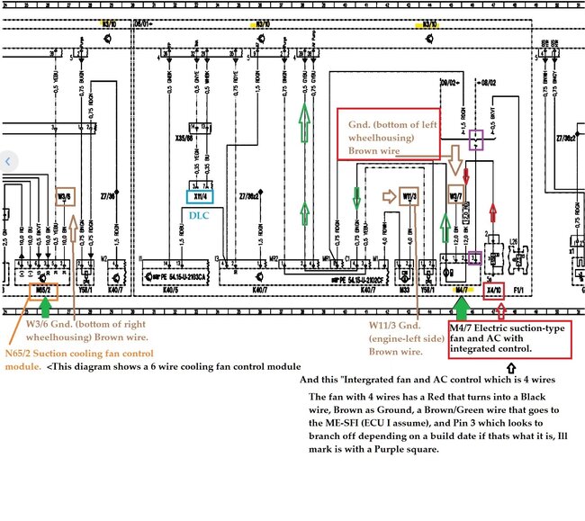
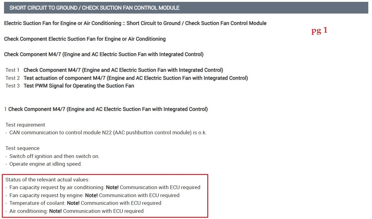
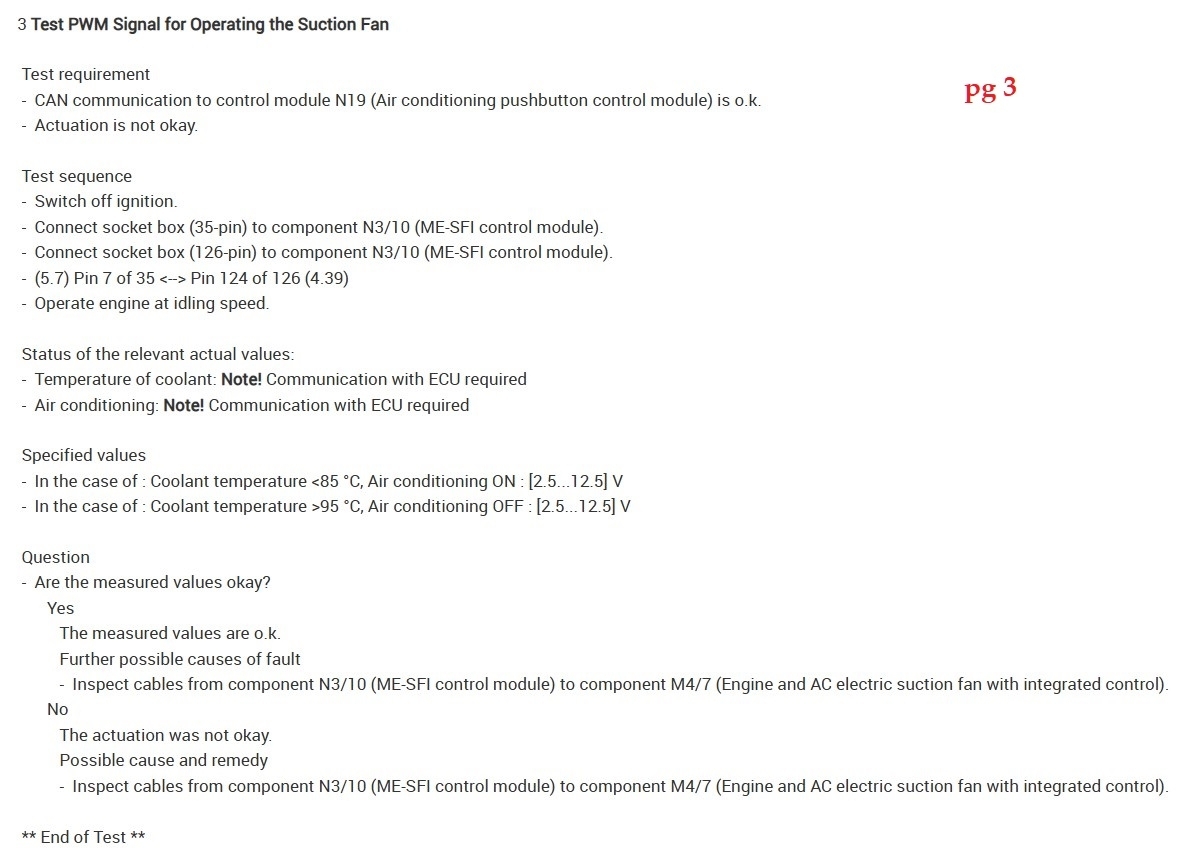
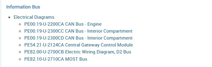
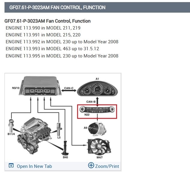
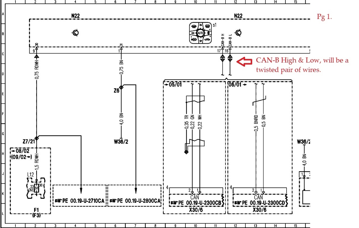
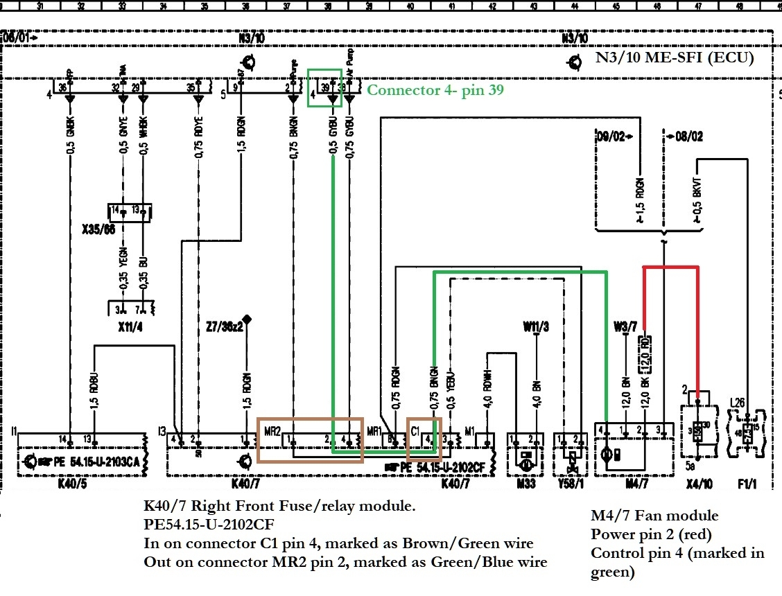
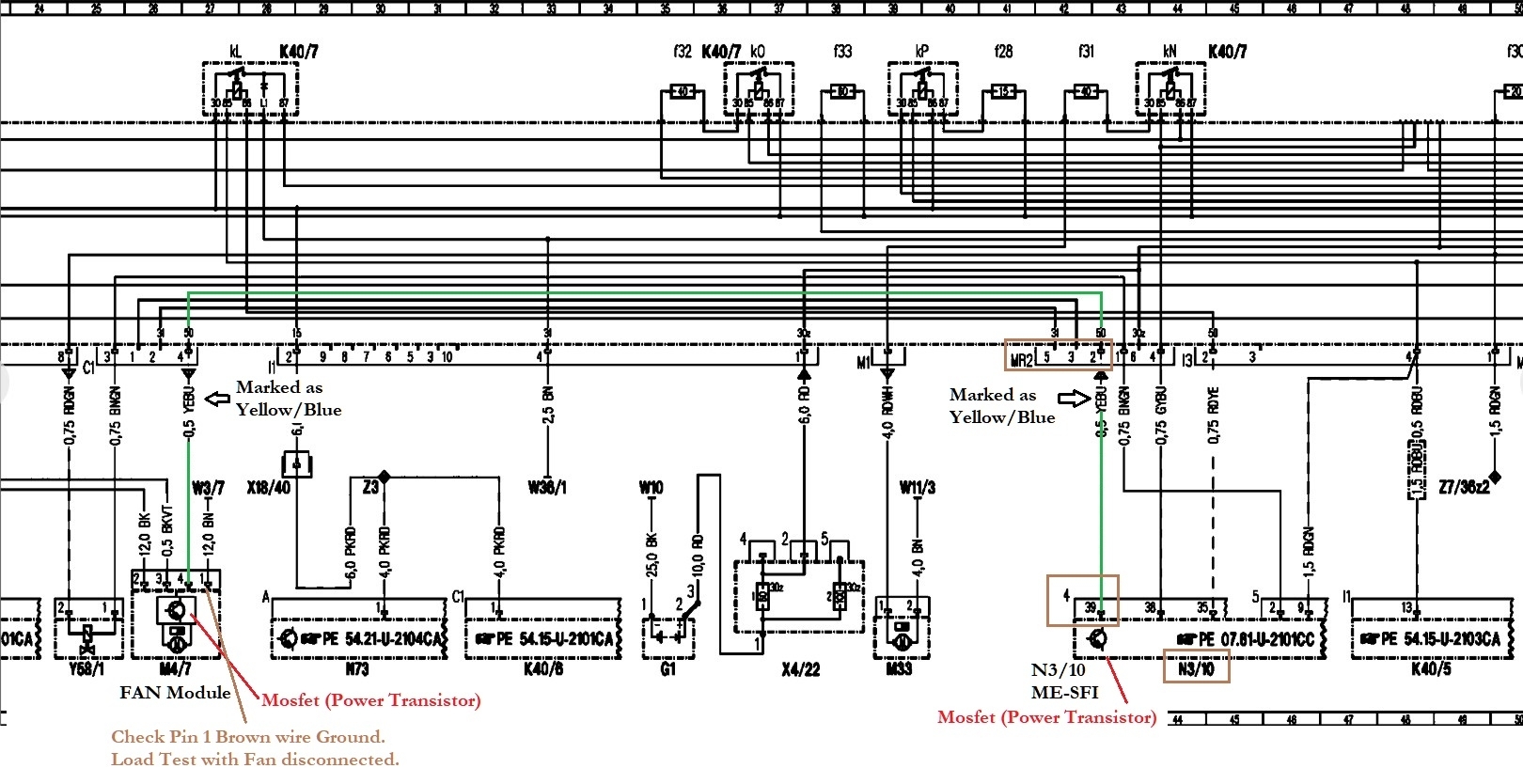
I’ve checked the wire from the ECU to the radiator harness. There is a signal to the radiator fan from the ECU. No breaks in the wire as the wire showed continuity with my multimeter.

The ECU was checked for any shorts, damage, etc. It seemed clean and was put back into the car. Same problem still occurs of course.

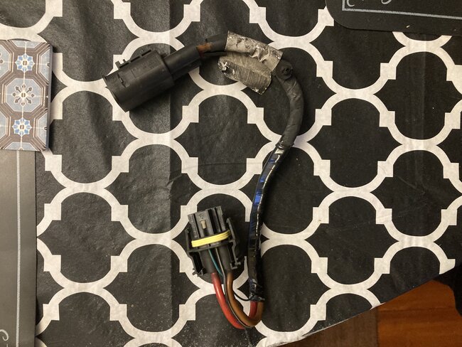
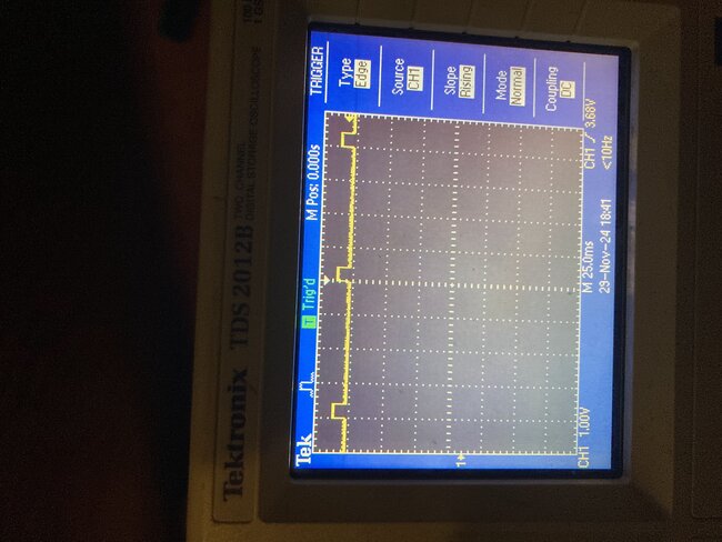
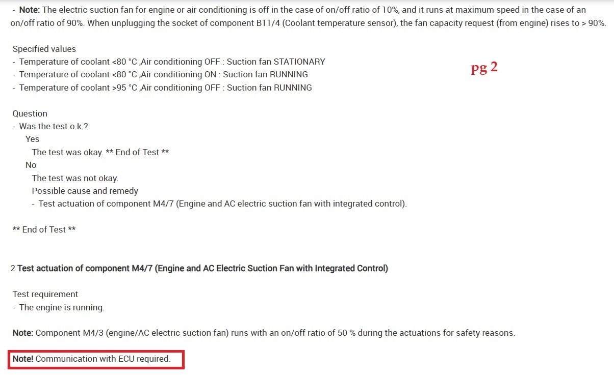
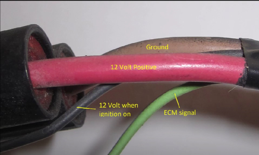
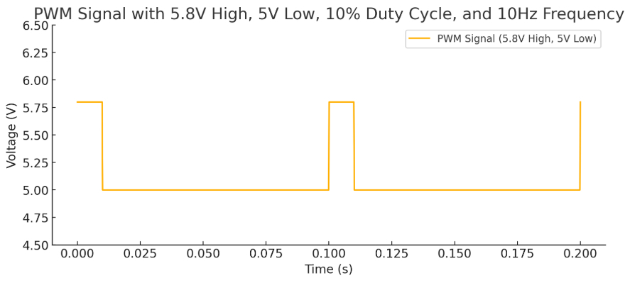
I checked the signal being sent from the ECU to the radiator fan when it was disconnected. It seemed that the ECU was telling the radiator fan to stay on based on the voltage (5-6V) when using an oscilloscope to check the signal. Not sure if this is because it’s a bad ECU, or if it’s because it’s in a “safe mode” because the harness is disconnected.

I’m stumped. It seems that even the coolant temperature sensors are ok because I don’t have a check engine light from those sensors. What should I do?
Nov 27, 2024 at 12:45 AM
Advertisement
Avatar
AL514
  • CERTIFIED EXPERT
  • 5,462 POSTS
Hello, so you're sure the DME(ECU) is in Limp Mode (or fail-safe mode)? Not sure what Merc calls it. I would check your live data for the engine computer, see what the coolant sensor is reading for temp and voltage, and also check to see if there is an AC pressure switch that is reading high, I will go through the wiring diagrams and see if there's an AC pressure switch or 3 wire sensor.
And what harness do you have disconnected? A loss of communication with an engine computer can cause the fan to run on high all the time as a default strategy, you might have communications with a scan tool if it communicates on a different network than the rest of the modules. Also did you try a full system scan to see if any modules are offline or have codes stored in them? It's good you have a scope, maybe take a look at the network waveform for any corrupt messages, but this also I will have to look at some wiring diagrams as well.
Nov 27, 2024 at 12:27 PM
Avatar
AL514
  • CERTIFIED EXPERT
  • 5,462 POSTS
If you have the ECU unplugged right now, I would take a look at the Can Bus network with it unplugged and then plugged in and see if you noticed any differences in the waveforms. The engine is listed as having its own Can bus which then communicates to a Gateway Can bus that has the Data link connector on it, unfortunately there are no redrawn wiring diagrams for this year, only the OEM wiring diagrams. But if the ECU is unplugged, the fan will default to high speed, at least that's what I have seen in the past. But don't rule out an input causing the fan speed to be high as well.
Nov 27, 2024 at 1:53 PM
Advertisement
Avatar
SOMEONE12132
  • MEMBER
  • 70 POSTS
The ECU is not in limp mode, and the car runs and drives just fine. Here is what I have done. I have done a full system scan, and none of the systems are offline. When I am talking about the harness, I am talking about the harness connecting to the radiator fan. There’s a wire within that harness from the ECU to the radiator fan that sends a signal to the radiator fan to turn it on/off.

I seem to have communication with my CAN Bus, and have no fault codes over there according to my ECU. I have a few codes with the A/C but doing some research yields that these codes are minor and affect barely anything.

My engine coolant temperature sensor reads fine. It was 60 degrees Fahrenheit or 16 degrees Celsius when taking measurements, and the coolant temperature sensor read 16 degrees Celsius.

I did notice that my A/C pressure sensor reads 4 Bar, which may be too low. Not sure if this is a bad A/C sensor, or a leak. Could this cause the radiator fan to get stuck on high in ignition and with the engine on?

I've listed a few pictures along with the codes and data from each thing, such as the A/C sensor, the coolant temperature sensor, request for fan on/off, etc. Let me know if I should check anything else.
Nov 27, 2024 at 5:45 PM
Avatar
AL514
  • CERTIFIED EXPERT
  • 5,462 POSTS
What's the rest of the B1340 code? Because according to your live data there's no request for the Fan to be on by the engine or HVAC system, the Refrigerant pressure is only 58psi and the temperatures are not in a range to run the fan on high, so I would look more into that B1340 code, I think this communications Error for the AC system Bus is where to concentrate. The fan might be default in this case as well if there is a loss of communication because the control module may not know the Actual pressure or temperature of the system and have the same effect of a loss of comms with an ECU, defaulting the fan on high to protect the system from damage since it may not have accurate or any data from the control module.
I looked up the B1340 code and all data doesn't even have it listed, and there are only OEM wiring diagrams, which makes it more difficult to identify the correct wires. But the Can bus wires will usually always be a twisted pair of two wires, since they are communications wires.
This is the direction I think I would take with this diagram, on the wiring diagram the N22 module is the Air Condition Control module (diagram 7).
Nov 27, 2024 at 9:33 PM
Avatar
SOMEONE12132
  • MEMBER
  • 70 POSTS
Is there any sort of forum post or something to confirm this is the issue? I have not heard of this code triggering the radiator fan to go on full blast.

Anyways, the B1340 Code is a Communication Error of AC Bus With Component B32/2(AAC Sun sensor (4 in total)).

I also have a B1350 Code, which is a Communication Error of AC Bus With Component B31/2(Air Humidity Sensor).

Do you know what the AC Bus is, and where is it located? Also, it is worth mentioning that I did disconnect the battery in order to disconnect the ECU, which may have reset the ECU. Could resetting the ECU also trigger these codes?
Nov 27, 2024 at 10:54 PM
Avatar
AL514
  • CERTIFIED EXPERT
  • 5,462 POSTS
I did find a diagram with the Sun Sensor (4 in total), just looking through for a humidity sensor diagram as well. The AC Bus is going to be the Can Network that the Heater & AC system is on. This vehicle looks to have 6 Can networks. The Interior Climate control section is showing 2 different types pf fans, An Electric suction-type fan for the engine and
an Electric suction-type fan for the engine and AC with integrated control.

I am finding that if there is no output signal to the fan it will run on high, very high as a default mode. So, with seeing your scan tool data of 0% Request if the engine is running, that's the cause of it switching to high speed, and just staying on, Thats the same function I've seen other vehicles do to protect the engine from overheating.
Is the live data of the Coolant Temp sensor of 16c when the engine is running?
There is also supposed to be a TSB for a fan harness update which I'll look for.
Nov 28, 2024 at 11:34 AM
Avatar
AL514
  • CERTIFIED EXPERT
  • 5,462 POSTS
You mentioned a voltage reading around 5-volts, was that a square wave looking signal on your scope or just a straight 5-volts?
Nov 28, 2024 at 11:45 AM
Avatar
AL514
  • CERTIFIED EXPERT
  • 5,462 POSTS
Because if the pwm signal was coming from the ECU it would be a pulsed signal, but the ECU is reading 0% request, so it might be a 5volt reference shorted to the fan control wire. But it seems odd that there are network codes as well, the interior climate control function diagram shows the right front Sam module controls the fan from various inputs.
Nov 28, 2024 at 11:52 AM
Avatar
AL514
  • CERTIFIED EXPERT
  • 5,462 POSTS
But heres the Sun Sensor and Humidity sensors locations. but I would monitor the network and look for any message packets that look distorted, see what the oil temperature sensor is reading as well. But the fan is running on high because its missing a signal, or at least the ECU is not seeing any signal from your scan data.
Nov 28, 2024 at 12:08 PM
Avatar
SOMEONE12132
  • MEMBER
  • 70 POSTS
The signal is pulsing at 5V. It was a square signal for sure. It would pulse from 5V to 5.8V. It would never go to 0V. There would be an initial spike at 10V when the ignition is switched on. Also, the harness to the radiator is disconnected while testing all this, and the car is in ignition.
Nov 28, 2024 at 2:51 PM
Avatar
AL514
  • CERTIFIED EXPERT
  • 5,462 POSTS
Yeah that doesn't sound right, I've been trying to find a wiring diagram for the fan in different locations, nothing yet, I'll keep looking, but without it pulling fully to ground, and I would expect the fan to be a pwm of 12v to 0 not only 5volt,

but service info on the fan operations is stating the ME-SFI control unit indirectly actuates the fan through the engine/AC electric suction fan control unit. So, the control signal from the ECU might be a lower voltage signal but I would still expect the signal to pull fully to ground. Maybe there is a bad ground here somewhere, and the fan is defaulting to high speed because the fan suction control unit is only seeing a voltage level averaging 5-6volts.

The next section states "The status of the air conditioning or automatic air conditioning is transmitted from the instrument cluster via the CAN to the ME control unit. The fan specified speed is dependent on this status".

Theres a harness section (diagram 3) you can check, it came up as a diagnostic location.
There is also a connector pinout diagram for the ME-SFI control unit and the diagrams for the fan engine and AC with integrated control unit, which Ill post these diagrams as well.
It does show the grounds which you can check. I'll post these next.
Nov 28, 2024 at 3:45 PM
Avatar
SOMEONE12132
  • MEMBER
  • 70 POSTS
I forgot to also mention a couple things. I have a CLK 55 AMG. Also, I think I have the wiring harness adapter that the TSB had mentioned. The only thing I can tell with this adapter is that there is a 10 ohm resistor in it from the ECU, but I’m not sure if this will fix it. The ECU looks like it has been changed from the TSB/recall originally mentioned for these 03s.

Also, my scanner has an option to change the coding on my radiator fan. I have attached a picture of this, and maybe changing the coding for now may fix this issue? It seems one relies on the AC to turn on the fan, and the other relies on the temperature to turn on the fan. I’m not exactly sure what this is supposed to do though.

Nov 28, 2024 at 4:47 PM
Avatar
AL514
  • CERTIFIED EXPERT
  • 5,462 POSTS
Here is the wiring diagrams for the ME-SFI control module and the fan wiring to it with the connector and pinouts for the ME-SFI (ECU).
Nov 28, 2024 at 5:05 PM
Avatar
AL514
  • CERTIFIED EXPERT
  • 5,462 POSTS
Well, I see a red, brown, green, and is the last wire black?
And are there 4 pins in the female side of the connector?
Nov 28, 2024 at 5:10 PM
Avatar
AL514
  • CERTIFIED EXPERT
  • 5,462 POSTS
Yeah, I've been getting the diagrams and info for a 2003 Merc Benz CL 55 AMG V8 5.5L.
Nov 28, 2024 at 5:16 PM
Avatar
AL514
  • CERTIFIED EXPERT
  • 5,462 POSTS
I wasn't able to find any TSB number listed for this vehicle, do you have the TSB number for that extra fan harness?
I would load test those grounds and make sure they can carry a good amount of current, this could just be a bad ground, especially on a vehicle this old. And they need to be more than just a visual inspection, it needs a good load test with at least a 4 amp test light to be sure they aren't breaking down under heavy load.
Nov 28, 2024 at 5:20 PM
Avatar
SOMEONE12132
  • MEMBER
  • 70 POSTS
I don't have the TSB number for that extra fan harness. It came with the car when I bought it, but the harness was kept in the trunk and never connected. I do have a link to a forum with the information about the faulty fan fires.

Here is the link for that: https://mbworld.org/forums/clk-class-w209/68028-new-tsb-faulty-fan-wires-apparently.html

Supposedly, the CLK 55 AMG's are susceptible to this issue, but it seems to have been resolved as the ECU looks replaced.

Anyways, I have a picture of the signal I am getting from the ECU using my oscilloscope. Could any other module, sensor, etc. cause this? Peak voltage is at 3.75V with the harness connected, reference voltage is now at 3V, and there is some sort of pulsing going on. Without the adapter harness, this would show at 5V with a peak voltage at 5.8V.

Also where are the grounds on my CLK 55 that I should check?

The harness has red, brown, green, and black wires. Red -> power, Brown -> ground, Green -> ECU signal, and Black -> Ignition signal.
Nov 28, 2024 at 6:40 PM
Avatar
AL514
  • CERTIFIED EXPERT
  • 5,462 POSTS
You don't know how refreshing it is to have someone who uses a scope. Thats really great, so you're saying the 5v Ref for some sensors is now only 3volts? Or what reference voltage are you referring to?
Sorry about the ground locations, they were on this list, but difficult to see,
These are the grounds for the ECU diagrams section that listed the fan as well.
If a bad sensor is affecting the 5volt Ref, and that ref is shared with other sensors internal to the ECU, it can cause strange symptoms, usually a sensor shorts out and just pulls the 5vRef to ground, which can cause the ECU to completely shut down.
So, your scope is set to 1v/div, so the signal is riding on 5volts, with these small jumps of 0.8v every 100ms, and this is happening on the red wire?
The grounds listed below are all Brown wires, just fyi.

Check some other 3 wire sensors on the engine to see if anything else has a low reference voltage, being at 3volts is very strange, that almost makes me think there might be something wrong with the voltage regulator, then again you said the vehicle runs fine, I'm going to message a tech that works on Euro vehicles all the time and see what he thinks about the fan, the problem is these wiring diagrams are terrible,
You scope waveform looks like that wire is possibly shorted to a 5volt wire or a bad ground can cause elevated voltage.
I did find this small flow chart for the "Suction Fan Control Module- Short to Ground" (diagrams 3-5), and then there is also a section for short to power, but its the same exact flow chart. It does say that communication is required which you have a code for. But service info lists every code as being a "P" code and not B, I don't know if that's something to do with that specific scan tool communications or not.
Part of the flow chart on pages 2&3 mention an Actuation test of the Fan, which is going to be a bi-directional control, and probably monitor the Fan speed data PID while doing so,
Diagram 6 shows a list of the different Can networks in the vehicle.

But I think the real issue is a loss of comms with the ACC pushbutton control module (N22) since the sun sensor and the humidity sensor both input to that module, and that might be why they are setting B codes, and not powertrain codes.
The ACC control module looks like the control head for the heater and AC.
Thats the main unit at the top of the HVAC wiring diagrams (#8 below) N22, very in-depth system with a ton of modules.
Nov 29, 2024 at 12:36 PM
Avatar
SOMEONE12132
  • MEMBER
  • 70 POSTS
Sorry for the confusion, but the reference voltage according to my scope is 5V without the "TSB Harness" connected (TSB Harness is referring to that extra fan harness that came with the car). That harness has a 10-ohm resistor in it. With "TSB Harness" connected, the reference voltage is 3.5V. There is no fluctuating in the reference voltage. 3.5V with the "TSB Harness" connected, and 5V reference voltage without the "TSB Harness" connected. The scope was set to 1V/div, and the signal is riding on 5V with these small jumps of 0.8V every 100ms without the "TSB Harness".

This scope reading is also not on the red wire, but rather the green wire as that is the wire that sends a PWM signal from the ECU to the radiator fan. I'm not sure if when you're referring to the red wire, you are talking about the signal wire. I have a picture posted below of what wires I see going to the radiator fan. It seems to be a 4-wire connector going to the fan.

Also, if it was the AAC pushbutton control, wouldn't the A/C request for the fans be at 100% instead of 0%?

I also did notice that on my A/C, there is a giant 0 that is displayed. There is definitely a fault with the A/C, but I'm not entirely sure if this is what causes the radiator fan to stay on.

I'm also taking a look at this video: https://www.youtube.com/watch?v=osK1lLzOAvw&ab_channel=LMAutoRepairs

He has the same issues as me, but unlike me, his radiator fan gets stuck on high with the engine running only, not in ignition. For me, it is stuck on high in ignition and with the engine on.
Nov 29, 2024 at 3:59 PM
Avatar
SOMEONE12132
  • MEMBER
  • 70 POSTS
Alright, I believe something is wrong with my ACC that may be messing with the radiator fan. I cannot turn on air-recirculation in ignition, and none of the button's work. How can I go about repairing this?

Also, all I know is that the fuse is good for the ACC, and that I believe I have communication to the module as I was able to pull all those codes.
Nov 29, 2024 at 4:09 PM
Avatar
SOMEONE12132
  • MEMBER
  • 70 POSTS
Actually there’s a correction here. The recirculating button doesn’t work, but the other A/C controls work. Would disconnecting these sun sensors and humidity sensors fix the problem?
Nov 29, 2024 at 7:14 PM
Avatar
AL514
  • CERTIFIED EXPERT
  • 5,462 POSTS
I'm not sure disconnecting the sensors would be a fix, it might just be setting codes for those sensors because of a lack of comms to that ACC module, just and effect and maybe not the cause. Because you also have codes for the Recir actuator as well, the B15C0 "Right Fresh air flap". They call these components all kinds of confusing names, but also theres a Blower Regulator code too.
When I suspect a bad module or an issue with a module, I first check powers and grounds by load testing them to make sure they can carry current, I have a few turn signal bulbs and some lower current bulbs set up on the 4mm meter connectors so I can use them with a back probe, and then to check the Can bus coming out of the module I would de-pin just the Can wires so the module it still plugged in, but isolated from the network, then scope just the two pins on the modules connector to see if any message packets are coming out, because if its not isolated you will read the others modules on that network.

To get really technical you could decode the Can messages, (you would need to use a Pico for this unless your scope can decode messages) then unplug the AAC module and then decode the network again to see if theres any module IDs missing, meaning the ACC is missing from the network when unplugged, this is a much more time consuming route,

But this is the Sun sensor location, I would have to locate the humidity sensor because its not just for humidity, its a multifunction sensor that reads a bunch of different things such as air quality and some others, I dont remember all of it, but it does a lot.
Im kind of surprised other modules are not setting codes for no comms with the AAC module, Im just going over the AAC diagrams again, it takes forever to find a single component on these diagrams, it looks like the Can bus wires run to the "Cockpit Voltage distributor connector" (so a Can Splice pack), you may be able to seperate the wires coming from the AAC module from there and check its output alone, thats what I would do considering you have communication codes.
Do you want me to post these AAC diagrams again. It does show the blower regulator, the sun sensor wiring, etc.
Nov 30, 2024 at 12:13 PM
Avatar
AL514
  • CERTIFIED EXPERT
  • 5,462 POSTS
I've gone through and labelled some of the components on the AAC module diagrams (2-4 below) and you can find each on the list (diagram 1), it's just a matter of locating the letter and number listing, and diagram 5,6 are for the Multifunction Sensor (humidity sensor). These cars are tough to work on, even for a 2003, it takes more time to do research in service info than anything else. You can try unplugging some sensors and see if the AAC unit starts working again, it does look like the sun sensor works off a 12v reference that comes directly from the AAC unit itself.
Nov 30, 2024 at 12:43 PM
Avatar
SOMEONE12132
  • MEMBER
  • 70 POSTS
I'll definitely take a look at these sensors. However, I have a strong feeling that something is wrong with my signal, not due to these sensors. If something was wrong with these sensors to mess with the radiator fan, I feel that they will send a signal to request for the radiator fan to come one.

When it comes to PWM signals, shouldn't the signal oscillate from 0V to the spec voltage (ex. 0 to 5V) with a frequency of 10Hz and a duty cycle of 10%? It seems that I have the proper frequency of 10Hz and duty cycle of 10%, but the signal seems wrong as my signal never goes back to 0, but rather to 5V, then oscillates to 5.8V. I would really like to know what the signal should look like, because after doing some research, I'm getting all sorts of answers. However, many of these answers show that a PWM signal goes back to 0V after every pulse. I would like to know how the PWM signals should look like on a radiator fan to a CLK 55 as this could point towards a more serious issue of it being my ECU.

I have also attached an image of a graph I plotted to show what I am seeing on the oscilloscope to make it easier for everyone to see.
Dec 1, 2024 at 2:44 AM
Avatar
AL514
  • CERTIFIED EXPERT
  • 5,462 POSTS
Yes, I understand your waveform, it should be pulling to 0volts (ground), that why I mentioned that wire might be shorted to a different wire somewhere, just looking at these diagrams again trying to identify the wire you are reading this signal on, they have the fan connector labelled as M/3x1, which I see here, unfortunately they have the fan connector cut off at the section where it goes to the next page of the diagrams, and since this is the original OEM wiring its showing a 2 wire connector (a Black wire and a Green wire), whereas the TSB shows a 4 wire connector,
I am going to try to paste these pages together so we can see exactly where the fan control module gets its inputs from, its looks like the "Right Front fuse and relay module"

The waveform is strange for sure, the really difficult part is that after this x1 fan connector the wires look to change colors going to the control module (the N65/2 Suction cooling fan control module). The Green wire goes to red (+) and the black (-) wire goes to blue.
So, your waveform is on the red wire, is that correct?

Service info states the fan will default to high with a loss of communications, I agree the issue is probably not the sensors, they are just setting codes because a module is not receiving data from them, so we're on the same page here.
I think some of these fuse boxes are mislabeled as well, but just so I'm looking at the correct wire, regardless of if its labelled incorrectly, your waveform is on the red fan wire. I know I've probably asked that already, but I'm looking at the power distribution diagrams now as well.
Dec 1, 2024 at 3:14 PM
Avatar
SOMEONE12132
  • MEMBER
  • 70 POSTS
I doubt that my wire is shorted because I am able to read a constant PWM from the ECU when the car is on. If it was shorted, shouldn't the reading be 0V from the wire from the ECU?

I'm not too worried about the other wires besides my PWM wire from the ECU. For me, my power wire is red, ignition wire is black, ground wire is brown, and my green wire is a direct connection to the ECU. I'm not entirely sure what diagram you are looking at because my fan doesn't have an external control module, but an integrated control module that is within the fan. I believe the TSB "4 connector" diagram is the right one.

I don't believe there is a "loss of communication", but rather my signal being improper, causing this problem to occur in the first place.
Dec 1, 2024 at 4:21 PM
Avatar
AL514
  • CERTIFIED EXPERT
  • 5,462 POSTS
Okay, that helps, they have each system all on the same diagrams, I found the 4 wire cooling fan unit, so pin 2 should be the Red power wire from a fuse, but the control wire coming out on pin 4 runs back through the K40/7 Right Front fuse/relay module on (connector C1 pin 4) then out on (connector MR2 pin 2) to the ECU (N3/10) connector 4 pin 39. I will post the diagram of that with the ECU connector,
I was meaning that the wire might be shorted to a power wire, not ground, such as a short to a 5volt reference and that's why it's not pulling to ground. But let me get this diagram together for you. Obviously, the wire colors are not completely correct.
Dec 1, 2024 at 4:56 PM
Avatar
SOMEONE12132
  • MEMBER
  • 70 POSTS
A diagram would be greatly appreciated. I believe there is a little bit of a mistake I made on measurements. It seems that my voltage reading goes to 3.5V on the off cycle, and 3.8V on the on cycle from the PWM signal from the ECU.

What wires could I check in the meantime that this wire might be shorted to? A wire that is 3.5V whenever the car is on and is shorted PWM wire would likely be a good place that I could check.
Dec 1, 2024 at 5:34 PM
Avatar
AL514
  • CERTIFIED EXPERT
  • 5,462 POSTS
Okay, the 1st diagram is the cooling fan integrated unit with a 4 wire connector, so with the fan unplugged you should read 12volts on the red wire Pin 2 since it's supposed to come from a fuse, so I would verify there's a full 12volts there, you could use pin 1, the Brown wire as your ground when checking that, Pin 3 is also supposed to be 12volts,
The Fan module shows a power transistor (Power Mosfet) inside of it on the Power Distribution wiring diagram, but also shows another transistor on the other end where the wire runs into the ECU, so I would scope across the red and control wire with the fan unplugged, and see if you have a normal pwm signal, that way you can isolate the issue to either the fan module or ECU, even go right to the ECU and scope there to make sure there's no shorts to power inside that Right Fuse/Relay module. Breaking down the circuit like that can help figure out where the fault is faster, I'd be curious to see what readings you get on each wire with the fan module unplugged. It's kind of strange the route the circuit takes.
Dec 1, 2024 at 5:36 PM
Avatar
AL514
  • CERTIFIED EXPERT
  • 5,462 POSTS
3.5volts sounds like a CAN High signal, does it drop to 2.5volts on the low side?
Dec 1, 2024 at 5:37 PM
Avatar
SOMEONE12132
  • MEMBER
  • 70 POSTS
I read 12 volts from the red wire using the brown wire as ground. Pin 3 also reads 12 volts.

Also, the CAN signal does not drop to 2.5V. Instead, it drops to 3.5V and peaks at 3.8V each cycle.

Back-probing the wire near the ECU and getting the signal from there yields the same results in my scope (3.5V to 3.8V each cycle).
Dec 1, 2024 at 6:11 PM
Avatar
AL514
  • CERTIFIED EXPERT
  • 5,462 POSTS
What do you get with the fan unplugged, do you get a 0v-12v pwm? A Can High signal would be 2.5 to 3.5v and Can Low would be 2.5v down to 1.5v, riding on a 2.5volt bias level, so that's probably not a can signal then. I'll see if I can find any operations info on the fan, but I still think the Bus codes are a factor.
Dec 1, 2024 at 6:21 PM
Avatar
SOMEONE12132
  • MEMBER
  • 70 POSTS
This is with the fan unplugged. If it were the A/C bus codes causing issues, would the duty cycles increase? It seems that my frequency and duty cycles match up to how they are supposed to be. It's just the voltages seems super wrong.
Dec 1, 2024 at 6:33 PM
Avatar
AL514
  • CERTIFIED EXPERT
  • 5,462 POSTS
So the fan is blasting away on high with only a 3.5-3.8 voltage signal? Does the blower motor work at all, or any of the climate controls?
Dec 1, 2024 at 6:35 PM
Avatar
SOMEONE12132
  • MEMBER
  • 70 POSTS
The blower motor works on the climate controls. Yes, the radiator fan is blasting always on high with that PWM signal of having a low of 3.5V and a high of 3.8V.
Dec 1, 2024 at 6:51 PM
Avatar
AL514
  • CERTIFIED EXPERT
  • 5,462 POSTS
Okay, a quick random search showed a B1350 code is a Can Bus Communication Fault on a Merc, the scan tool might not be interpreting the code numbers correctly, which is not uncommon, scan tool data is not always correct,
I would see what the waveform looks like for some of the Can bus networks in the vehicle, the easiest to check is the data link connector, pins 6 and 14 are the two can high and low pins, Pins 4 and 5 are grounds, unfortunately service info doesn't show a picture of the DLC in this vehicle, but pin 16 is always B+, so you can identify pins 6(high) and 14(low). And use 4(chassis ground) and 5(sensor ground) for ground connection.
If you see anything that's not square in the signal, such as a message packet that randomly comes by, that can be a single module sending out corrupt messages, or any lines that rise or fall with a sloped angle that can be a short between high and low, but just see what you find, you might just see a bad message every once and awhile, if you can set a trigger on your scope and adjust your time base, you might catch something, the messages are so fast though it can be difficult with smaller scopes. It's worth checking out though.
Dec 1, 2024 at 7:47 PM
Avatar
SOMEONE12132
  • MEMBER
  • 70 POSTS
I'll definitely take a look at this. I definitely have communication with my A/C bus as I am able to draw codes. Most likely it's the sensors that have gone bad.

Is it possible that I have a bad ECU?
Dec 1, 2024 at 8:29 PM
Avatar
SOMEONE12132
  • MEMBER
  • 70 POSTS
Hey, so I have an update. I recently found a fault (B1102), which indicates a fault in CAN communication to my ME-SFI (Control Unit). I found this code when checking for codes in my instrument cluster as I have heard about some people saying that they had issues with their radiator fan going on full blast because of the instrument cluster.

Source: https://www.slkworld.com/posts/4696895/ - This was with an SLK instead of a CLK, so I am not sure what are the differences between the SLK and CLK electrically.

Could this potentially cause my radiator fans to be on full blast? How would I go about diagnosing this if this is the cause of my radiator fans going on full blast?
Dec 2, 2024 at 8:30 PM
Avatar
AL514
  • CERTIFIED EXPERT
  • 5,462 POSTS
Hello, sorry for the delay, I had to go out on a mobile call yesterday, and yes to your question, its actually pretty common when there is an ECM (ME_SFI) communications issue for the fan to default to high, I have seen it before. The code numbers are not matching up with what the OEM has listed in some areas, but that's not uncommon as well. Do you know the location of the ECM? This is where your scope is going to be very useful. I know some of the ECMs are located in the engine compartment under the windshield cowl section, so you can scope the Can bus right at the ECM or at the splice pack for the Can bus, I would go right to the ECM, because if it is actually located in the engine compartment, there might be an issue with its connector(s) being corroded due to water intrusion.
Dec 3, 2024 at 11:02 AM
Avatar
SOMEONE12132
  • MEMBER
  • 70 POSTS
I do know the location of the ECM. It is located under the engine compartment under the windshield cowl. I have taken out the ECM from the car and have inspected the connectors and the pins on the ECM itself. No water damage or corrosions with the connectors.

Here's what I have done so far. My Can Bus High and Can Bus Low on the board is good as I am getting a 124 ohm resistance when checking it with my multimeter.

With the board out, what else can I check? Is there a schematic of the board layout? What part of the board controls the radiator fan? I can inspect the solder there to see if there is a bad connection to ground due to a cracked solder.
Dec 5, 2024 at 7:09 PM