No crank no start?

2007 CHEVROLET SILVERADO
121,000 MILES • 5.3L • V8 • 4WD • AUTOMATIC
Advertisement
Avatar
AL514
  • CERTIFIED EXPERT
  • 5,465 POSTS
Something else, I was just looking back at your original posts, at one point you mentioned you didn't have communications with the Fuel system, but it's setting a code for no comms with the BCM.
Before you go to all this BCM testing, let's unplug the Fuel Pump control module, and the transfer case control module, then rescan the truck.
These are known for issues because of the Fuel pump control module location above the spare tire, let's just try unplugging it and see what codes set. Make sure the key is off while unplugging modules.
Do them one at a time, scanning for codes in between. It's just a quick shot in the dark to see if either of them is messing with the networks. If nothing changes then go ahead with the BCM testing.
Aug 19, 2023 at 9:28 AM
Avatar
JAVIERMLNDZ
  • MEMBER
  • 51 POSTS
Here are the codes without the fuel pump control module connected.
Aug 19, 2023 at 11:00 AM
Advertisement
Avatar
JAVIERMLNDZ
  • MEMBER
  • 51 POSTS
I actually disconnected the transfer case control module last night and these are the codes I got. Still had the other U codes.
Aug 19, 2023 at 11:04 AM
Avatar
JAVIERMLNDZ
  • MEMBER
  • 51 POSTS
I just redid the disconof the transfer case control module and got these codes.
Aug 19, 2023 at 11:35 AM
Avatar
JAVIERMLNDZ
  • MEMBER
  • 51 POSTS
I rechecked the voltage on pin 10 dk Blu for transfer case control module and got 11.6 v. I think I got the wrong one last night and checked a dark blue with a white stripe, I checked this one right now as well and got 5v. My mistake.
Aug 19, 2023 at 11:45 AM
Avatar
JAVIERMLNDZ
  • MEMBER
  • 51 POSTS
Update BCM connection X1 pin 2=.05v, 4=.053v, 8=.01v, 14=12.25v, 17=1v, 21=12.2v
X2 1=.035v, 2=12.3v, 5=.02v, 22=.245v.
Aug 19, 2023 at 12:18 PM
Avatar
JAVIERMLNDZ
  • MEMBER
  • 51 POSTS
X3 1=ground good, 2=12.3v, 3=12.3v, 5=ground good, 8=2.7v, 9=2.3v, 10=.5-.7v, 12=.057v, 16=2.7v, 17=2.3v, 19=11.6v
Aug 19, 2023 at 1:28 PM
Avatar
AL514
  • CERTIFIED EXPERT
  • 5,465 POSTS
Okay, so you're missing some main power feeds there already. X1-pin2 should be 12v, pin4 should be the 5vRef, pin17 should be 12vRef coming out, and some other feeds on X3.

So, we need to figure out why those ignition feeds are missing.
Aug 19, 2023 at 1:49 PM
Avatar
JAVIERMLNDZ
  • MEMBER
  • 51 POSTS
X4 1=12.8v, 2=12.8v, 3=12.8v, 4=12.8v, 9= ground good, 10=12.8v, 19=12.1v
X5 13=12.8v, 14=8.8v
Aug 19, 2023 at 1:58 PM
Avatar
AL514
  • CERTIFIED EXPERT
  • 5,465 POSTS
So, it looks like all the power and ground feeds into the BCM are okay, they are at least there. But some outputs are not correct, this first one X1 pin4 outputs a 5volts to the Ignition switch and there should be some feed coming back on pin2 during Start, but the 5volts missing is strange. Then X3 pin12 should be another output 12volts reference which is not there. As well as there is no Low-Speed network voltage or its being shorted to ground by another module, but I don't know if that would take down the entire BCM. The X5 pin14 should also be 12volt ref output but its only 8.8volts. Which is also strange. I would think that the two 12vRefs would come from the same voltage regulator inside the BCM,
Unplug the comb/splice for the Low-Speed network, the one with all the green wires, and let's see if anything comes out X3 pin10. Let's see if the BCM outputs anything onto the Low-Speed Network then.
Aug 19, 2023 at 2:42 PM
Avatar
JAVIERMLNDZ
  • MEMBER
  • 51 POSTS
I got .012v with comb out at pin 10 x3.
Aug 19, 2023 at 2:58 PM
Avatar
AL514
  • CERTIFIED EXPERT
  • 5,465 POSTS
There is 1 Recall for the Chassis Control module along with some other module issues listed towards the bottom. There are also some Technical Service bulletins on BCM damage if a ground is temporarily lost. But it's always a difficult call to replace a module like this, there's also a TSB on problems with programming or reprogramming BCMs. I have seen quite a few of these fail, but I would be checking the High-speed bus with an oscilloscope to make sure there isn't something going on with the Terminating resistors, networks act strange when one of the resistors goes open circuit or if the Bus+ and Bus- short together.
The voltages you had with 2.7 and 2.3 are around the normal levels, but we have pretty much gone as far as we can go with a multimeter, all powers and grounds tested, the Low-Speed network output is completely missing, and some reference voltages are incorrect or missing.
When it comes to a no comms situation on a CANbus type network, we would start unplugging modules until the network came back to normal, but when the BCM controls everything, we can't do that and expect normal results. Plus, we have the Serial Data Comm Enable voltage, and Accessory Wakeup Serial Data voltage. But again, with that, we don't know if there are actual data packets being transmitted, or if that 12volt level is a short to voltage.

Diagrams 6 and 7 below are the final BCM testing flow chart before making a call on the module. Most of these we have already done and there is a warning about disconnecting any BCM connectors without disconnecting the Battery negative. But run through these and check anything you would like to. This flow chart has you unplugging modules testing for comms and then try replacing a Terminating resistor,

Read through those 2 pages and let me know if you want to try any of these tests. For example, on page 2 it has you disconnect the BCM connector 3 and attempt communication with the EBCM(ElectronicBrakeControlModule) and communication should not be capable. If it is replacing the ECM. This has to do with High-Speed comms through modules.

***The last thing we can do is check the Reference circuits coming out of the BCM, the 5vRef and the 12vRefs for any shorts to ground,
***The first one is to disconnect the Headlight Dimmer Switch. And check the Orange/White wire at the Dimmer switch for a returned 12volts. 8th Diagram
I'll find this other 12vRef as well.
Aug 19, 2023 at 3:50 PM
Avatar
AL514
  • CERTIFIED EXPERT
  • 5,465 POSTS
Okay, these are the (3) 12vRef that are missing and their connector and pin. X1 pin17, X3 pin12, and the X5 pin14 which was only 8.8volts runs to the Transfer case shift control switch and to the Outside Moisture Sensor near the Rear View Mirror.
You can try to disconnect each of these components, or a faster way is to cut the wire, check the reference voltage and if it returns to 12v, recheck comms with the BCM. Then repair the wire with a crimp connector after.
Aug 19, 2023 at 4:03 PM
Avatar
JAVIERMLNDZ
  • MEMBER
  • 51 POSTS
I started the circuit/system testing and on x2 pin 1,5 and 22 are grounded. That's with all connections unplugged for the BCM. Also on x3 pin 10 and 12 are grounded and on x5 pins 13 and 14 are grounded.
Aug 19, 2023 at 5:35 PM
Avatar
JAVIERMLNDZ
  • MEMBER
  • 51 POSTS
So, if I checked this right all the connection points are grounded, so there is a break in one of these wires? Or could something else ground this?
Aug 19, 2023 at 6:53 PM
Avatar
AL514
  • CERTIFIED EXPERT
  • 5,465 POSTS
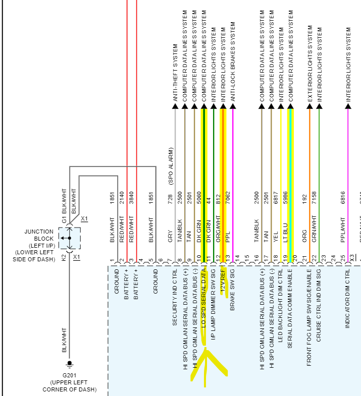
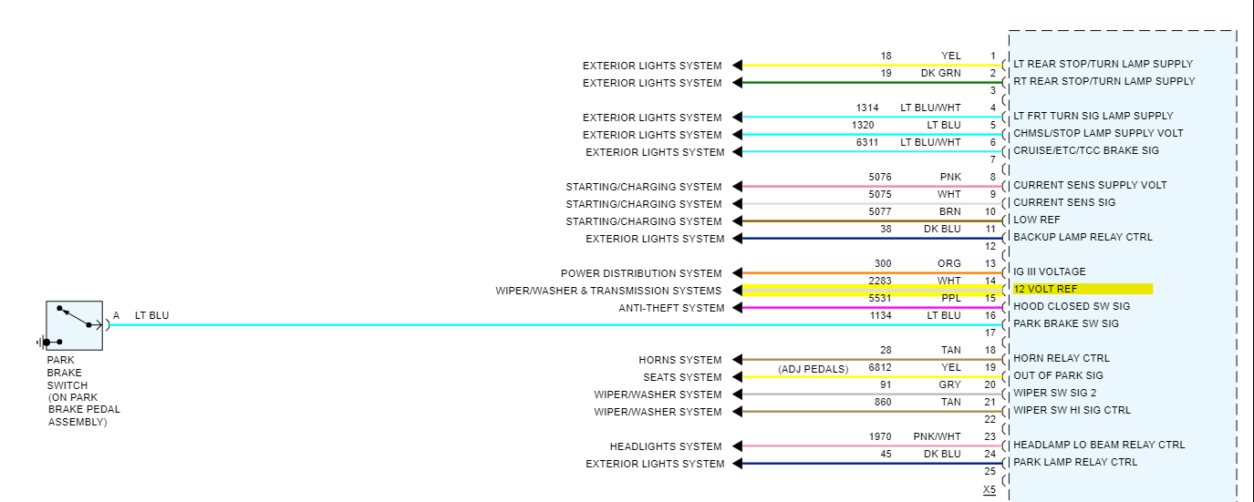
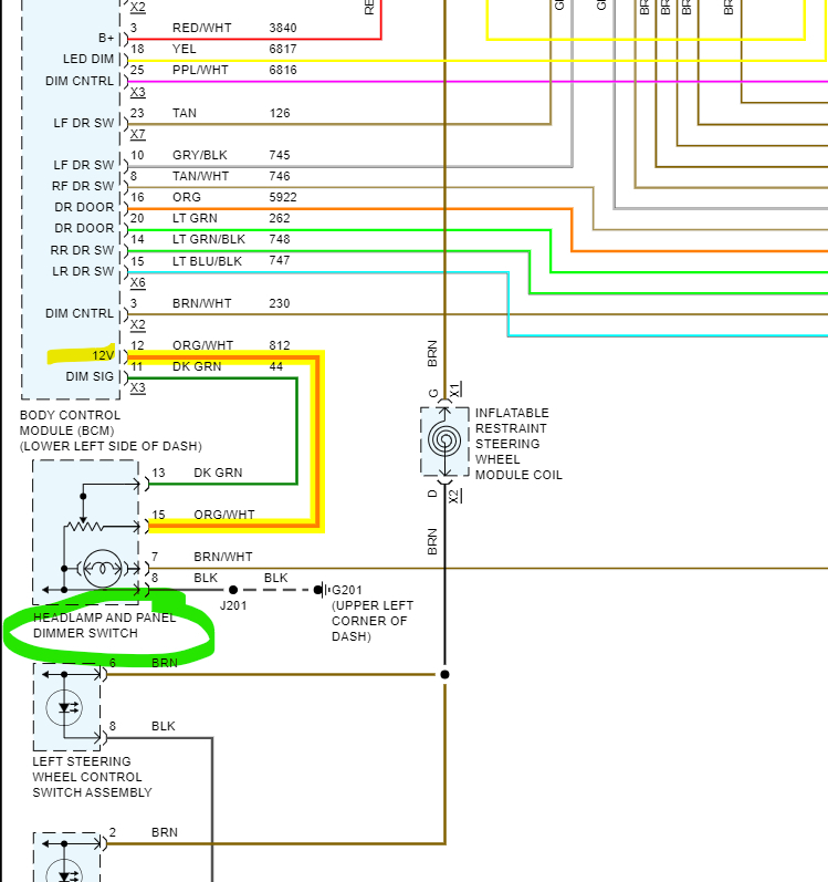
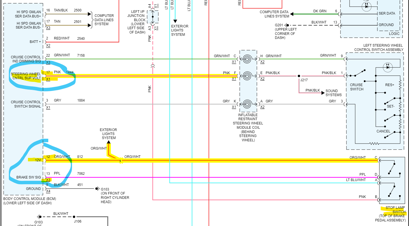
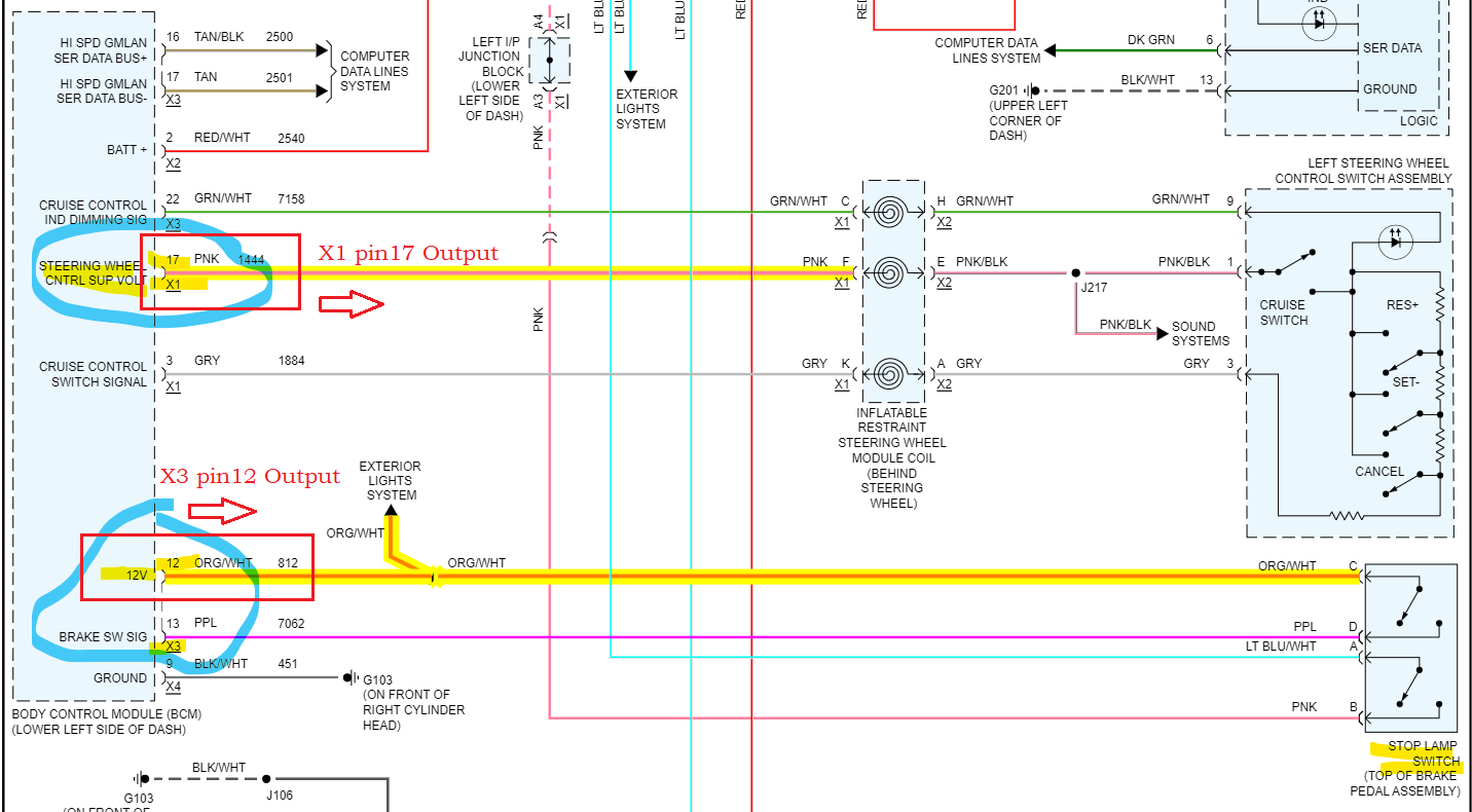
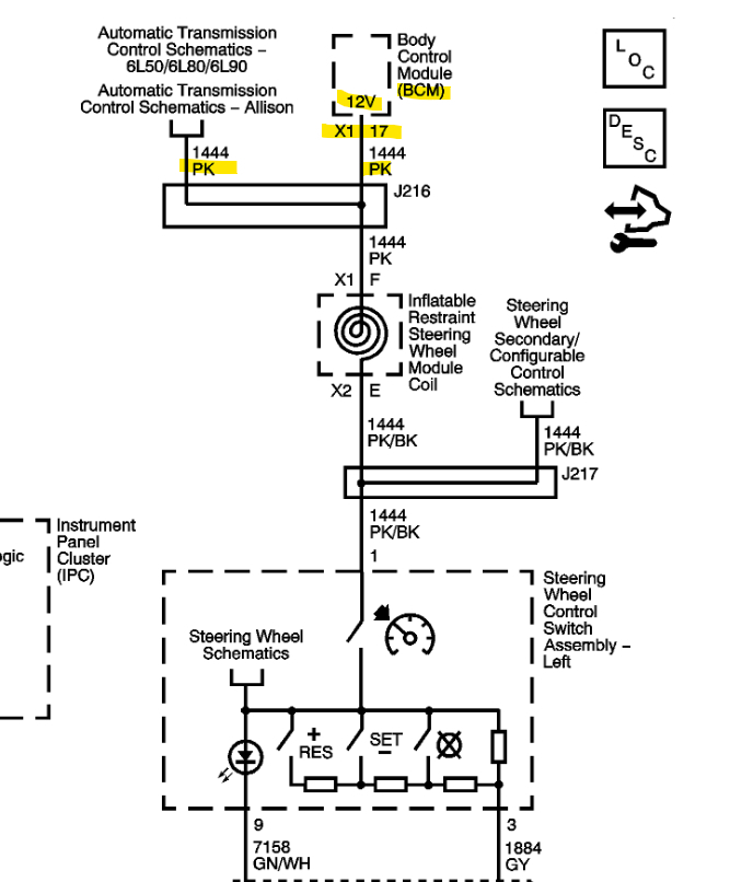
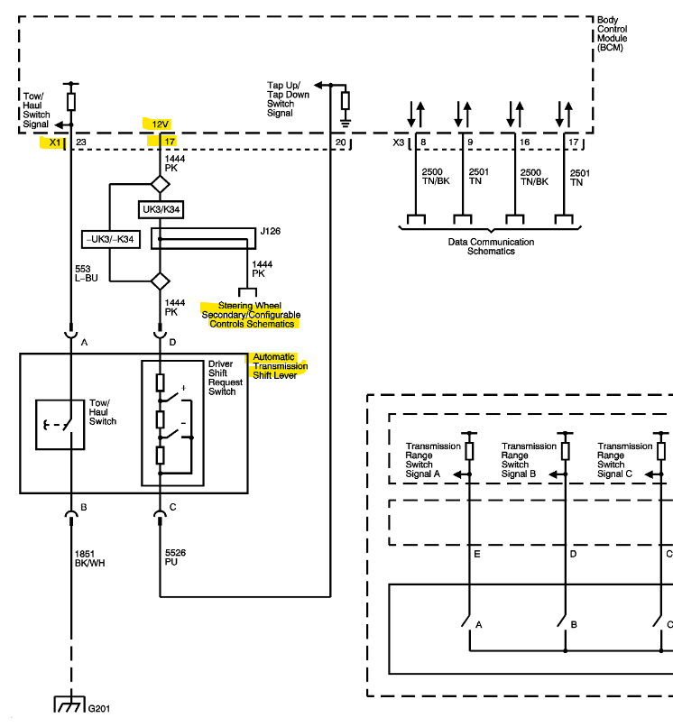
The X1 pin17 should have 12volts coming out of the BCM as a reference voltage for the Cruise Control switch.
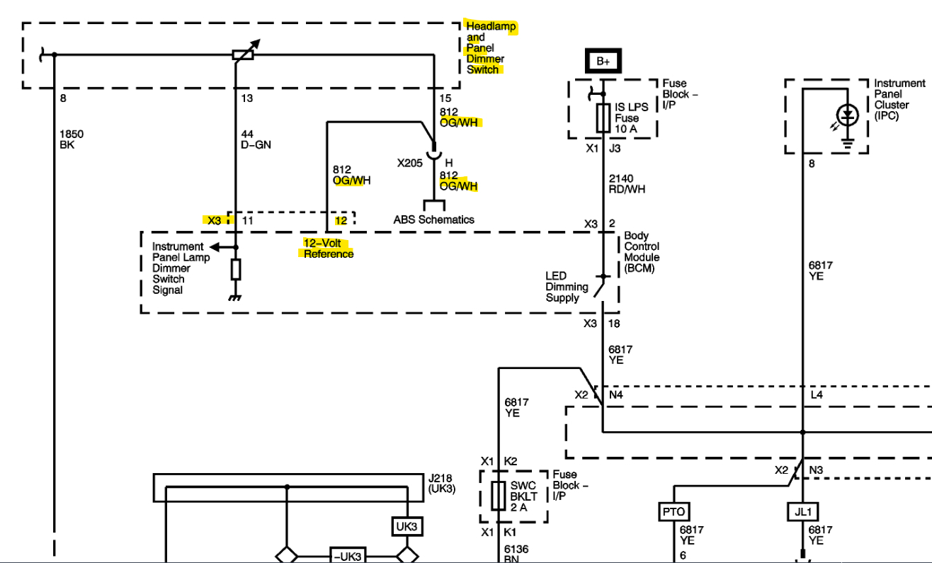
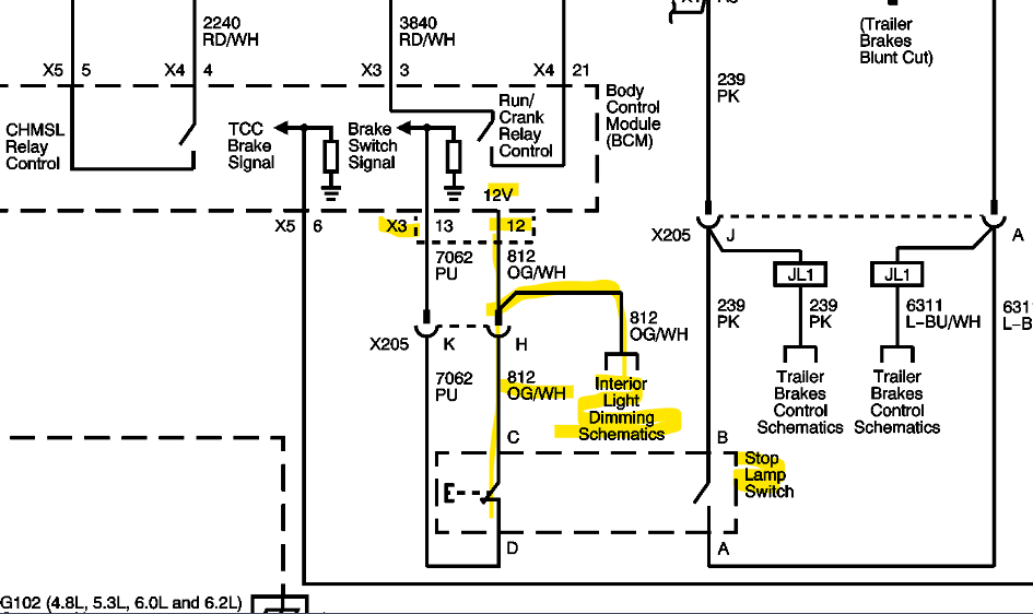
X3 pin12 should also have 12volts coming out to feed the Stop Lamp Switch (brake pedal).
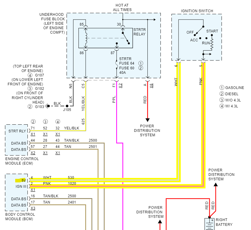
Sometimes what happens when a sensor shorts out it will pull that reference voltage down, this happens with the ECM as well. If the 5vReference on a sensor for the ECM gets shorted out it will pull that entire 5volt feed down, this also pulls the 5volts down for any other sensor using that same 5volt feed and can cause a no start situation for example.

So, the X3 pin12 feeds 12volts to the Headlamp/Panel Dimmer Switch and to the Brake Lamp Switch, so if you were to unplug both of those, then recheck X3 pin12 and see if the 12volts have returned. If it does happen to or not, leave both unplugged for now.
If the 12vRef returns to X3 pin12.
Also check the X1 pin17 for the full 12volts returning.
I don't think it will because they seem to be on different 12v circuits internally to the BCM.

Next move on to X1 pin17 12volt output is more complicated to unplug the switches and components it goes to, it feeds the Steering Wheel Control switch, it also branches off to the Transmission Shift/Request Lever. So, it would be too difficult to unplug all those.
The concern with this circuit too is that it looks to feed the Steering Wheel air bag module, The only way to be sure on this 12vRef, would be to cut the wire at the BCM leaving enough to crimp that wire back together after checking for 12volts coming back, That BCM pin was only at 1volt, when it should be outputting 12v.

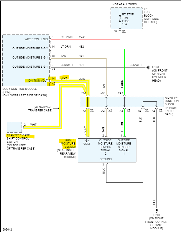
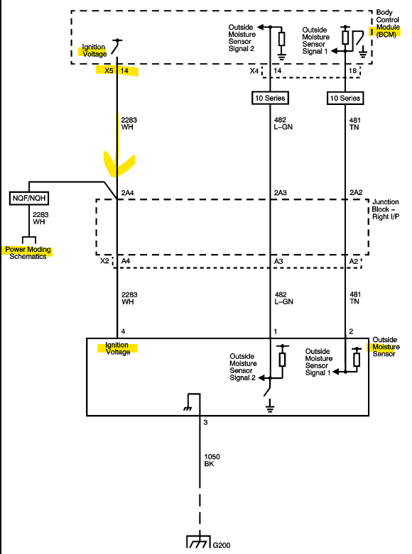
X5_pin14 was the last 12vRef output. The one that was 8.8volts that should be 12v going out to the Outside moisture sensor and the Transfer Case Shift control switch. Another one that will be difficult to unplug.
But this is how difficult diagnosing bad modules is. If any of these reference voltages is being shorted out, it might be causing the BCM is shutdown partially because of a fault like that.
And this doesn't even include the missing 5volt Reference to the Ignition switch. Some techs will take the chance and just replace the BCM. But if it's replaced and the same condition still exists, then all these circuits need to be checked.
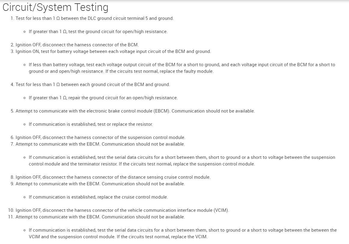
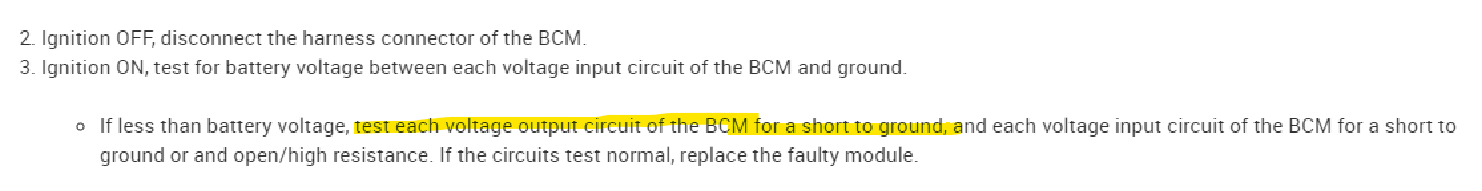
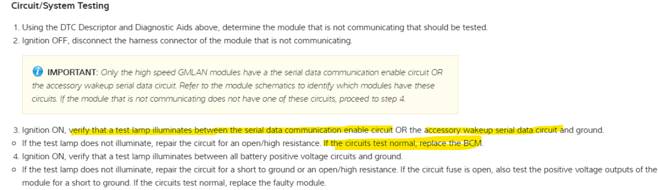
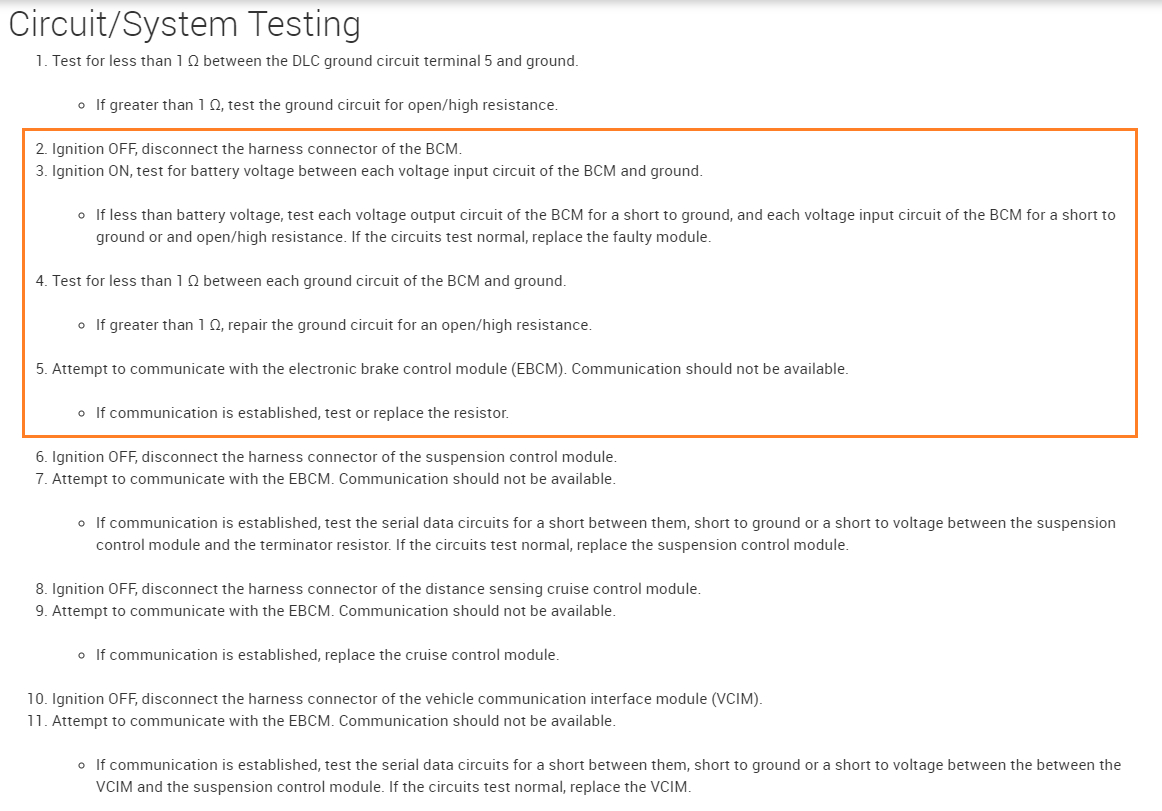
Even in the Flow Chart it states there to disconnect the BCM connector and test each voltage output of the BCM for a short to ground, as well as the inputs.
But you can't unplug these connectors to check that 12v output refs we're looking at here because we don't know exactly which connector provides input power for those 12v outputs.
This is why disconnecting the outputs component to check for it being shorted is necessary. You will read some sort of ground through components, but they need to be checked while power is applied. The BCM is either bad or has some reference outputs shorted somewhere. There's no way to tell the effect from one to the other because we don't know the internal circuits that are shared or not. We have to know the output state of these pins with nothing connected to them.
Aug 19, 2023 at 8:08 PM
Avatar
JAVIERMLNDZ
  • MEMBER
  • 51 POSTS
Well, I went ahead and ordered a BCM module, but I will continue to do what you mentioned above. But I have a question, if something got shorted to ground that caused me this issue while I was driving wouldn't I have noticed something? I'm just saying because this just happened one morning while turning my truck to go to work.
Aug 20, 2023 at 8:48 AM
Avatar
AL514
  • CERTIFIED EXPERT
  • 5,465 POSTS
It was just a no start one morning. It depends on the fault, I had a 04 Chevrolet Colorado which had burned out a trace on the circuit board of the BCM and the truck would run, even with the BCM being completely offline. And what was happening was all the other modules in the vehicle would use the last known good data from the BCM and use that information to run, granted some systems were not functioning correctly which is why it needed to be repaired to pass inspection. But your truck uses the BCM as a way for the 2 (Low Speed and the 2 wire High Speed) networks to communicate together. We don't know the actual fault here though, so it's impossible to say what happened.

I think there's something else going on than just a bad BCM, or something caused the BCM to go bad. This is bothering me too much to just stop testing here.

Those low reference voltages are concerning. Plus, the no voltage case on the Low-Speed network is not right.
Check a couple more things for me really quick. At the Data Link connector where you plug your scan tool in, first check for 12v on pin 16 using pin 4 as Ground and then pin 5 as Ground. With the key on let me know if you have 12v on pin 16 first and both those grounds (4 and 5) are good. I assume it will be good with at least one of those Grounds. If 4 or 5 is not good let me know.
Next check the voltage on pin 1 using pin 4 and then 5 as ground. With the key on see what you get. If nothing on pin 1, we're going to pull the Splice pack and check each pin for voltage. Then we're going to see if there is another splice pack for the Low speed and pull that and recheck. You already know where there's one comb splice pack.
I don't want to see you install a new BCM and have it burn out due to a short or not resolve the issue.
I've been thinking about this all day, and I don't like the testing results yet, there are too many variables.
Aug 20, 2023 at 3:42 PM
Avatar
AL514
  • CERTIFIED EXPERT
  • 5,465 POSTS
Do you know if you have Rear Object detection option on your vehicle? Let's go through this quick. I think a module is pulling down the Low Speed network,, causing the no start, check under the rear bumper for Rear Object Sensor module, unplug it and recheck for voltage signal on DLC pin 1.
Aug 20, 2023 at 4:06 PM
Avatar
JAVIERMLNDZ
  • MEMBER
  • 51 POSTS
I do not have Rear object detection, I checked to make sure.
Aug 20, 2023 at 5:14 PM
Avatar
AL514
  • CERTIFIED EXPERT
  • 5,465 POSTS
Okay, but the Low-speed network having no voltage at all, can be the no start issue, we've just been through so much information on the BCM, we need to get a voltage on the Low-speed wires. It should be around 7volts. Just check Pin1 of the DLC and the two grounds 4 and 5.
When you mentioned that BCM X2 pin 22 was grounded, do you mean you had zero Ohms on that pin with the BCM unplugged?

Here is the 2nd Splice location for the Low-Speed network. Under the passenger seat with all dark green wires.

Take look at this video, it explains the GMLAN low speed network operations and what might be going on with your vehicle, having no voltage might mean that it's shorted to ground.

https://www.youtube.com/watch?v=Rwsfe4KT330
Aug 20, 2023 at 5:27 PM
Avatar
JAVIERMLNDZ
  • MEMBER
  • 51 POSTS
With x2 unplugged I connected the black probe to it and the red probe to ground and got 12.5v.
Aug 20, 2023 at 6:22 PM
Avatar
JAVIERMLNDZ
  • MEMBER
  • 51 POSTS
I also checked all the connections while they were unplugged, I got x2 pin 5 and 22, x3 pin 10 and 12, x5 pin 13 and 14, x6 pin 2, x7 pin 7 21 27 all grounded. Unless I didn't check them right but that's odd that all these would be grounded.
Aug 20, 2023 at 6:45 PM
Avatar
AL514
  • CERTIFIED EXPERT
  • 5,465 POSTS
So, connector X2 pin 22 unplugged showed 12volts? or is that coming out of the BCM pin?
X3 pin 10 should not be grounded, that's the problem with the Low-Speed network, there should be activity on that wire for all the other modules on the Low Speed.
This JX 339 is the other Splice comb that needs to be checked, there might be a module or short to ground pulling the network down completely.
Aug 20, 2023 at 7:14 PM
Avatar
JAVIERMLNDZ
  • MEMBER
  • 51 POSTS
Yes, x2 pin 22 unplugged gave me 12v. Along with the other ones I mentioned.
Aug 20, 2023 at 7:26 PM
Avatar
JAVIERMLNDZ
  • MEMBER
  • 51 POSTS
I didn't get any voltage on any of the pins except pin A fluctuated between .3-.5v. I also checked to see if they were grounded, and they were good but pin A gave me .3-.5 v also when checking for ground.
Aug 20, 2023 at 8:55 PM
Avatar
AL514
  • CERTIFIED EXPERT
  • 5,465 POSTS
The X2 pin22 is an Accessory voltage that should be coming out of the BCM.
With the BCM unplugged, can you communicate or pull codes from any other modules?
Try communicating with the EBCM(Electronic Brake Control Module).
Aug 21, 2023 at 12:50 PM
Avatar
JAVIERMLNDZ
  • MEMBER
  • 51 POSTS
I will try when I get home from work.
Aug 21, 2023 at 1:47 PM
Avatar
AL514
  • CERTIFIED EXPERT
  • 5,465 POSTS
Okay, you need to find the other Low Speed network splice comb under the passenger seat and unplug it and check to see if any low-speed activity comes back. I posted this case on the All-Data community as well to get some other techs thoughts on this. I'm concerned about that Low-speed network being completely down, I'm wondering if that being shorted out will pull down the BCM, because your scan tool is not showing any modules on the low speed at all. And it should be scanning every module in the vehicle. The BCM is the only module that is on both High and Low speed GMLAN. Hence the need to pull the other splice and check for anything coming back online.
Aug 21, 2023 at 1:52 PM
Avatar
JAVIERMLNDZ
  • MEMBER
  • 51 POSTS
Want me to check the splice underneath the passenger seat with the BCM module unplugged?
Aug 21, 2023 at 2:14 PM
Avatar
JAVIERMLNDZ
  • MEMBER
  • 51 POSTS
I can't see the first image.
Aug 21, 2023 at 6:16 PM
Avatar
JAVIERMLNDZ
  • MEMBER
  • 51 POSTS
With the BCM unplugged I can't pull any codes to any modules; I don't have power to the ignition switch when I turn it on.
Aug 21, 2023 at 8:03 PM
Avatar
AL514
  • CERTIFIED EXPERT
  • 5,465 POSTS
Sorry about that, I'm just now seeing your message, the other splice pack should be under the passenger seat, yes, it should have all dark green wires just like the other one, the wires might be a little darker than the other splice pack but still green. So, it seems like the BCM is still putting out the Enable and Wakeup voltages it should be, but you can't communicate with it. I just want to be sure that this is not being caused by another module on the Low-speed network pulling down the BCM. That could happen, I'm also going to check on All Data to see if I got any responses about the Low-speed network wake up signal. But when you find the comb under the passenger seat, make sure that it is the only connector you unplugged. Once you have the connector unplugged you should be able to see the comb inside that is splicing all the network wires together. The comb should still be inside the network splice pack. I don't believe they come out by just unplugging the outside connector, you might need a pair of needle noise pliers to get it out. Then check each pin for any voltage. Make sure the BCM is plugged back in first. Then turn the key On and check it. If voltage comes back., Leave that splice pack unplugged for a minute and check that voltage returned on the other one.
The JX 339 is a black 12 pin end connector.
Aug 22, 2023 at 12:44 PM
Avatar
JAVIERMLNDZ
  • MEMBER
  • 51 POSTS
Yeah, I found it. I thought removing the plastic white connector that has the metal looking comb attached to it was splicing all the wires together. With this removed I checked voltage on all the pins and didn't get anything except pin A. 3-.5v like I mentioned up above.
Aug 22, 2023 at 1:29 PM
Avatar
AL514
  • CERTIFIED EXPERT
  • 5,465 POSTS
still only 0.3 to 0.5volts? This is a difficult case. Without being able to scope the network and see if the High-Speed Bus+ or Bus- is showing something off, it's really tough making a call here.
Are you able to access any of the modules besides reading codes? Can you go into the ECM or TCM and read live data? or access the BCM or any other modules?
If we follow this Circuit testing flow chart, the no comms with the BCM unplugged points to a failed module, but I would expect Low Speed network activity, unless the BCM is responsible for a Wakeup signal to the Low Speed network, and I can't find any information stating that.
Aug 22, 2023 at 1:46 PM
Avatar
JAVIERMLNDZ
  • MEMBER
  • 51 POSTS
It's capable of reading some live data, but I can't go directly to the ECM or TCM. Here are a couple examples.
Aug 22, 2023 at 3:30 PM
Avatar
AL514
  • CERTIFIED EXPERT
  • 5,465 POSTS
Those are all ECM live data PIDs, it looks like it only reads ECM data. So it looks like the BCM is sending out the Accessory serial voltage and the Wakeup voltage, I posted the case study on the All Data community tech page and only got 1 tech who asked if you were able to communicate with the BCM. I posted the codes and what was happening but surprisingly did not get any other replies at all about it. I know these BCMs in these GMs fail constantly, the last thing to try is wiggling some sections of the harness around. Like the connector for the ignition switch, or any bulk in-series connectors. ECM connectors, etc. I would also take the cover off the BCM and check the actual circuit board for any burns marks or melted IC chips, if something shorted out and burned a trace on the circuit board you'll see it. The last BCM failure I dealt with was a short through the Radio on the Serial Data wire. It was clearly visible on the edge of the board. I was able to solder a trace over the burned section, had the customer unplug the Radio connectors and it was ok and restored BCM functions. That was a 2004. But the new BCM will need to be programmed, and there is usually always updated software versions, which you will need a higher end scan tool to do. Most likely the dealership will need to do this. Most of the time the VIN, mileage, and other stored information on the EPROM chip needs to be transferred over, and if its not readable from the old BCM then the actual EPROM chip is moved over on the circuit board. But this is the only information All Data has on programming.
Aug 23, 2023 at 9:48 AM
Avatar
JAVIERMLNDZ
  • MEMBER
  • 51 POSTS
I did take apart the BCM module the other day but honestly, I didn't see anything noticeable. Maybe one spot but I don't think so. When I get a chance, I'll take it apart again and see if I can take a few good pictures.
Aug 23, 2023 at 12:28 PM
Avatar
AL514
  • CERTIFIED EXPERT
  • 5,465 POSTS
It will be tough to see much by picture, but something to look for in your case, is cracked solder joints, since this happened after it was running okay, and had time to cool off in between drive cycles. When a solder joint cracks it will open the circuit when the board cools off due to expansion. This is where intermittent issues happen a lot, cracked solder joints are super hard to see unless you know which circuit is acting up, in this case we don't know. Here's some examples pf cracked joints on circuit boards. Most of the time you need a magnified glass to see ones like this. They will close the circuit when hot and open when cooled down. Look for these near the sections of board the go out to the pins of the connector first. Then work your way in. I think the BCM seems to be half working in your vehicle but doesn't seem to be waking up the low-speed network and in this vehicle the BCM and ECM need to be communicating together for the truck to start. And that's not happening. But you do have some scan tool communications on the high-speed bus. That wouldn't be happening if the Accessory and Wakeup signals were not there.

I did finally get a message from another tech about this, He states "Replace the BCM then, Your BCM is offline and not communicating which is the cause of all these DTC."
Aug 24, 2023 at 1:05 PM
Avatar
JAVIERMLNDZ
  • MEMBER
  • 51 POSTS
Update: I just received my new BCM module yesterday and installed it, my truck turned on with no more codes.
Aug 29, 2023 at 7:40 AM