No crank no start?

2007 CHEVROLET SILVERADO
121,000 MILES • 5.3L • V8 • 4WD • AUTOMATIC
Avatar
JAVIERMLNDZ
  • MEMBER
  • 51 POSTS
I have the truck listed above that was running fine until I tried starting one morning to go to work but it did not crank. I checked the battery, and it was good, I still got power to the dashboard. I attached pictures of the codes I pulled to see if anyone can point me in the right direction.
Aug 9, 2023 at 2:26 PM
Advertisement
Avatar
AL514
  • CERTIFIED EXPERT
  • 5,465 POSTS
Hello, are you able to access the Body control module with your scan tool? It looks like it's offline from the vehicles network. With all those Lost comms to BCM, it looks like your scan tool pulled codes from 5 modules, I'll post a diagram of the High-Speed data bus, from the codes it looks like about half of that network is possibly down.
The Body Control module (BCM) is the gateway module for the different networks in the vehicle, the High speed to the lower speed network, so if the BCM is down, that is why you are missing so many other modules with a full system scan.
Here is the location of the BCM, check the connectors for any corrosion or any wiring issues. Go through the fuses as well to see if there are any that are blown. Since there are such a limited number of modules you're detecting, I don't think the BCM is either not powering up or its not receiving a wake-up signal from the ECM.

https://www.2carpros.com/articles/how-to-check-a-car-fuse

https://www.2carpros.com/articles/how-to-use-a-test-light-circuit-tester
Aug 10, 2023 at 12:52 PM
Avatar
JAVIERMLNDZ
  • MEMBER
  • 51 POSTS
I'm not sure, I have the BlueDriver obd2 Bluetooth scanner, I'll be home in a few minutes.
Aug 10, 2023 at 1:08 PM
Advertisement
Avatar
AL514
  • CERTIFIED EXPERT
  • 5,465 POSTS
Refresh this page, I posted some more information in my last post.
If you pull out the Run/Crank Relay and turn the key On, there should be battery power on 2 of the pins where the relay sits, Power for the H labelled circuit to the relay comes from the Ignition Switch, through the BCM to the Run/Crank Relay. If one of the power feeds is missing, we'll know where to start checking. Power for the Ignition switch comes from the DLIS Fuse 36 in the engine compartment Fuse Block. These BCMs can fail for a number of reasons, since they control so many circuits, a short can take them down pretty easy.
Aug 10, 2023 at 1:10 PM
Avatar
JAVIERMLNDZ
  • MEMBER
  • 51 POSTS
The only blown fuse I found was the 20-amp Aux PWR on the inside fuse box, I am going to try disconnecting the battery and connecting the positive and negative terminals to drain the vehicle to see if it resets everything.
Aug 10, 2023 at 1:29 PM
Avatar
AL514
  • CERTIFIED EXPERT
  • 5,465 POSTS
I posted some additional info, refresh the page again.
Aug 10, 2023 at 1:32 PM
Avatar
JAVIERMLNDZ
  • MEMBER
  • 51 POSTS
Disconnecting the battery didn't do anything. I did what you said and disconnected the Run/Crank relay and pins 30 and 86 gad power with key on pin 85 is grounded. I added a picture of my dashboard, there is no communication with the fuel system, and you can't see in what gear I'm in.
Aug 10, 2023 at 1:53 PM
Avatar
AL514
  • CERTIFIED EXPERT
  • 5,465 POSTS
Okay, this Aux fuse that you found blown is also in the same junction block left I/P, lower left side of the dash as the High Speed GMLAM Serial Data bus runs through. So, I would check for possible water intrusion or corrosion in that junction block. Thats the lower driver side dash.
Aug 10, 2023 at 3:20 PM
Avatar
JAVIERMLNDZ
  • MEMBER
  • 51 POSTS
Is this it? I don't see anything wrong.
Aug 10, 2023 at 3:47 PM
Avatar
AL514
  • CERTIFIED EXPERT
  • 5,465 POSTS
That's the front side of the Junction Block, the X2 and X3 connectors that have the High Speed GMLAN data wires. The ones running to the BCM. The 1st diagram is the front view of it, the 2nd diagram is the back side of the Junction Block.
The X2 and X3 connectors have the BCM network wires running through them.
The 8th diagram is all the modules and the entire network in the vehicle. The BCM is in the top right corner, its lost comms to the number of modules, and it's also the module preventing the truck from starting, so there is either a communication issue to and from the BCM or it is having some other wiring issue. As for this large junction Block, I'm not sure if it runs through the firewall or if you can get to the back side connectors to check X2 and X3.
The BCM is also located up under the driver side dash area (diagram 10).
On your code scan you can see that it's not even in the list of modules, so it's not communicating at all, and might not be powered up. Last one I had like this was a single trace burned on the BCM circuit board, causing all kinds of issues. GM runs more things through the BCM than any other module.
Aug 10, 2023 at 4:16 PM
Avatar
JAVIERMLNDZ
  • MEMBER
  • 51 POSTS
This is all I'm able to see on the back side, don't have that much movement. From what I can see the wires look okay.
Aug 10, 2023 at 5:02 PM
Avatar
AL514
  • CERTIFIED EXPERT
  • 5,465 POSTS
I know it looks like a tight fit back there, but that's where the BCM data wires branch out.
Diagrams 1-5. If you want to check the BCM comms on the Low-Speed network, there is a Splice Pack(comb) diagram 6,7,8 that you can check for a voltage signal from the BCM on pin M. These GM splice combs make it easy to check if a certain module is pulling down the Low speed network, If the BCM is not powering up at all, there will be a signal missing on the M pin, you can actually pull the comb out that connects all the modules together at that splice, and check that single wire from the BCM for a voltage signal.
The first diagrams are going to be more difficult to get a reading on the high-speed network. Just one other thing, if you plan to unplug the BCM to check the connectors for corrosion or anything like that, there is a TSB that states to disconnect the battery negative cable before disconnecting any of the BCM connectors or the module can be damaged. That blown fuse though is something that might point to the issue. Does that circuit still short to ground if you replace the fuse? If so, there is a wire touching ground and there might be more issues in that area.
Aug 10, 2023 at 5:59 PM
Avatar
JAVIERMLNDZ
  • MEMBER
  • 51 POSTS
I replaced the fuse and it hasn't blown yet.
Aug 10, 2023 at 6:13 PM
Avatar
JAVIERMLNDZ
  • MEMBER
  • 51 POSTS
Is that the splice you are talking about?
Aug 10, 2023 at 6:46 PM
Avatar
JAVIERMLNDZ
  • MEMBER
  • 51 POSTS
I was able to find the jx221 splice and removed the comb to check pin m and it did not have voltage.
Aug 10, 2023 at 8:35 PM
Avatar
AL514
  • CERTIFIED EXPERT
  • 5,465 POSTS
Yes, that looks like the splice comb for the low-speed network. The BCM communicates at both High speed and low speed and transmits messages across the two as a gateway. So, if you had no voltage with the key On, did you have voltage on any other pins? If possible, de-pin the M pin for the BCM and see if you have any voltage on that network without the BCM involved. It sounds like the BCM is not even powering up. Can you access it? It's got a 7-connector setup, this one looks to be pretty far up in the dash on the driver side, they are not usually in such a bad location, but if you can unbolt it without unplugging it and get it down where we can check its powers and grounds. That will be our next step. Did you try cranking as well and see if it blows that fuse again, I'm just concerned because it happens to run through that same connector X2 and then X4.

The good thing about those network combs (splices) is that we can pull modules off the network one by one there when diagnosing a problem. And the BCM is not setting any codes, that's a worry too.
Also, in the location circled in green, that first pin on the X2 connector, is there a Red/White wire coming out of that location. It doesn't look Red with a White stripe to me, but zooming in on the pic it gets pretty blurry, I'm wondering if these diagrams are incorrect in some places. Unfortunately, that is common.

I've come across many electrical TSBs for this model. There are all kinds of wiring issues under the dash
Diagrams 3-13 are TSB 1 with harness problem areas to check.
14.15 are TSB 2
16,17,18 are TSB 3.
And there are many more electrical TSBs, but they have to do with more wiper function and having to re-crimp connections that are faulty from the factory.
But these ones are about a very in-depth checking of the fuse panel in the engine compartment. For fuse/relay connections. So, a lack of power to the BCM from one of these more main power supplies is possible here too, there are many problem areas here. Since the BCM seems to be the first concern here, checking for power and ground, and then also any communication voltages right at the BCM connectors will let us know what its missing.
Aug 11, 2023 at 9:21 AM
Avatar
JAVIERMLNDZ
  • MEMBER
  • 51 POSTS
I believe this is the jx221 splice comb you mentioned at first and no I did not have any voltage or at any of the other pins with the key in the on position. I also cranked it a few times, but I do not recall checking to see if I had any blown fuses after that. I am currently out of town with the family de-stressing lol! I won't be back till Monday afternoon, hopefully I can take another look at it then. And no, I did not de-pin the M in this splice and check for voltage if this is the splice you are talking about.
Aug 12, 2023 at 4:54 AM
Avatar
JAVIERMLNDZ
  • MEMBER
  • 51 POSTS
Here is another picture, the first pin in the x2 connector looks to be brown.
Aug 12, 2023 at 5:06 AM
Avatar
JAVIERMLNDZ
  • MEMBER
  • 51 POSTS
And what 7 connector setup are you talking about here. The jx221 splice that I circled earlier in other picture with all green wires?
Aug 12, 2023 at 5:17 AM
Avatar
AL514
  • CERTIFIED EXPERT
  • 5,465 POSTS
The Body Control Module has 7 connectors on it. This is how you can identify it easier.
Yeah, I was looking at that X2 connector as well, Service info is not always correct so we have to do the best we can with what we have. In your 3rd post up, that module with all the colored connectors almost looks like the BCM, except I count only 6 connectors, I think. I'll double check that. I have seen so many BCM failures on these GM setups, any shorts seem to just disable the entire thing. but usually what happens is all the other modules with use the last known good data from the BCM to keep the vehicle running, which is why I think there is an issue with the High-speed network, The High-speed modules are the more important modules such as the ECM, TCM, ABS, etc. Things that have to do with safety, And the low speed is for lower priority components. But I want to help you get this thing back up and running.

On your full system scan you should have had a long list of modules, but you only had 4. And there's 8 on the High speed and about 18 on the low speed. So, we see some missing for sure. But there are some checks you can do on the Data Link connector with a multimeter that will give us some good information to work with also. So, enjoy your weekend and I'll have some testing ready for you when you get back.

And yes, you are correct on the jx221, all the wires are green. There are actually 2 splice packs like that. Diagram 2 shows all the Low-Speed modules and diagram 3 is all the High-Speed modules. And the BCM is the gateway between the 2 networks, so you can see it being down causes all kinds of issues. Also, you can see the High-speed mods are all 2 wire network connections, GM calls is a GMLAN Serial Data bus, but its actually a CAN BUS type. Its 2 wires so if a circuit fault occurs most of the time messages can still get through for safety reasons. But only 4 out of all those modules is setting codes,
So, I'm wondering if the BCM is missing this Wakeup Serial Data message (diagrams 4,5) or if its missing power or ground keeping it offline.

One last thing, I did a part number search, and this is the BCM in diagram 6, thanks for taking that picture, which helped a lot. Apparently this one only has 6 connectors, unless you see a 7th, but that is the correct part number for a 07 Chev Silverado 5.3L.
Aug 12, 2023 at 10:31 AM
Avatar
JAVIERMLNDZ
  • MEMBER
  • 51 POSTS
I appreciate all the help! Forgive me I am very green at this lol! And yes, the BCM does have 7 connections.
Aug 12, 2023 at 11:33 AM
Avatar
JAVIERMLNDZ
  • MEMBER
  • 51 POSTS
It's very odd to me that this would happen without any other signs of things going on.
Aug 12, 2023 at 11:35 AM
Avatar
AL514
  • CERTIFIED EXPERT
  • 5,465 POSTS
No worries, I'm just glad you happened to take that picture, now we can check the BCM. I pulled all the diagrams for each connector already. So, we can check each connector with a multimeter on Monday. I need to run out for a mobile call really quick anyway, so just post back when you're home and destressed. =)
Aug 12, 2023 at 11:42 AM
Avatar
JAVIERMLNDZ
  • MEMBER
  • 51 POSTS
Now that I recall a couple of weeks ago, I had the stability track light come on while I was on the freeway and then it went away after turning on the truck the next time. Maybe this is tied in with my current problem.
Aug 12, 2023 at 11:48 AM
Avatar
AL514
  • CERTIFIED EXPERT
  • 5,465 POSTS
That's probably why that History code C0455 (Steering position sensor circuit malfunction) is stored in the ABS module. The actual only codes that are Current/History are the U0140(ECM lost comm to BCM), U0140(TCM lost comm to BCM), U0140(Chassis/Fuel System Control Module Lost comm with BCM),

So really the U0140 is the only active code, with these other codes are obviously an intermittent issue. Most likely a temperature or moisture related condition. We need to focus on what is happening with the BCM to begin with. When you get back, clear the codes out again and see what comes back at key On and then cranking. Considering the BCMs location and all the harness contact points that are listed in this TSB, and its where your feet are moving around down there, pressing pedals and such. I think the issue is going to be under the driver's side dash. The diagram below shows where the steering wheel position sensor is, right down where your feet will be.

Something else I find interesting is the comms code for the Fuel Pump control module is Current Diagram 2 shows that modules location under the rear of the vehicle, Near the spare tire, worst place to put a control module, but also if you look at the 3rd diagram, that's the bottom of the High Speed network diagram, there are 2 terminating 120 Ohm resistors at each end of the 2 wire high speed harness. One of the terminating resistors is inside the ECM and the other is basically strapped to the rear crossmember of the vehicle. Another terrible place to put a very important circuit component. (Diagram 3,4)
With both terminating resistors in the 2 High speed bus, and because the 2 wires run in parallel, you can measure the entire resistance of that network from the Data Link connector and should have a 60 Ohm reading. I know that's a lot to take in at once.

But we'll first check what voltage readings we have at the BCM first and deal with anything that is missing.
Aug 12, 2023 at 2:50 PM
Avatar
JAVIERMLNDZ
  • MEMBER
  • 51 POSTS
Thanks, will do when I get back.
Aug 12, 2023 at 3:07 PM
Avatar
AL514
  • CERTIFIED EXPERT
  • 5,465 POSTS
Okay, enjoy the rest of your weekend.
Aug 12, 2023 at 3:14 PM
Avatar
JAVIERMLNDZ
  • MEMBER
  • 51 POSTS
Well, I got home late on Monday and had to run some errands yesterday so I didn't really have time to look at the truck, should have some time after work today.
Aug 16, 2023 at 6:27 AM
Avatar
AL514
  • CERTIFIED EXPERT
  • 5,465 POSTS
Okay, I can't believe how many of these Chevy 5.3 and 5.7liters we're getting lately, that are all no start cases, Its one after another lately. But let me know when you want to start checking some circuits.
Aug 16, 2023 at 11:26 AM
Avatar
JAVIERMLNDZ
  • MEMBER
  • 51 POSTS
Hopefully, I can look at it for a little bit after work today, I work 12s 7am-7pm so doesn't give me much time. I do have all day Saturday though.
Aug 16, 2023 at 12:01 PM
Avatar
AL514
  • CERTIFIED EXPERT
  • 5,465 POSTS
Okay, well, at least you already know where the BCM is located, with some codes being labelled as History codes, especially the Transfer case control module having lost comms with 4 other modules at some point, there has to be a corroded connector somewhere. What is odd is that the transfer case module comms code with the BCM is not Current, but the BCM is not setting any codes of its own. So, do another full system scan when you get a chance and see if any other codes show up. It might be that the transfer case module is offline now as well, unless some codes here are the scan tool not setting the correct Current codes, but with the key on. clear them out and see which comes back. Modules can do very strange things when there are corroded connections. They can be ok one day, and not the next depending on outside humidity and temperature. Hopefully we can find a fault pretty quick.
Aug 16, 2023 at 1:59 PM
Avatar
JAVIERMLNDZ
  • MEMBER
  • 51 POSTS
So, I cleared the codes and checked it again and got the same codes. I also checked the data link connector and got 61 ohms at pin 6 and 14, 14v at pin 16, 2.67v at pin 6 and 2.3v at pin 14.
Aug 16, 2023 at 9:07 PM
Avatar
JAVIERMLNDZ
  • MEMBER
  • 51 POSTS
Also, do you have any idea where this rubber hose would go? I found it hanging but had no idea where it would go, it's by the transfer case. I noticed the transfer case already has one connected to it.
Aug 16, 2023 at 9:09 PM
Avatar
AL514
  • CERTIFIED EXPERT
  • 5,465 POSTS
That looks like an overflow hose for maybe the transmission, I'd have to look that up later.
But are the codes for the codes for the Transfer case module say "Status History" by them?
That high-speed voltage looks pretty bias, at least from there is not shorted to power or ground,
I was doing some reading up on how the BCM in your vehicle interacts with everything else and from what I read, at least part of the BCM is working because you are able to pull codes from other modules, So it might be that the BCM is lacking one or more powers and grounds, or what else I've seen with these BCMs is another module might have shorted to ground and damaged the low speed communications section, but we'll figure that out when we get into testing the BCM itself.
What I found last night was that the BCM needs to send out first an Accessory Wake Up voltage (Serial Data) for other modules to power up and this happens when the Ignition switch first hits the Accessory position, and it also needs to send out a Serial Data communications Enabled voltage. And those 2 wires are both separate from each other. So those must be happening if you're able to pull codes from a few modules on the High-speed side of the networks.
There are some testing we can do with the BCM unplugged and using a scan tool try to access certain modules. We'll try that too and see what results we get; the testing is difficult because the BCM plays such an important role in everything.

Just as a reference for you, in the diagram below shows the Acces Wake up on the dark blue wires and the Serial Data Comm Enabled is the light blue (greenish) looking highlighted wires. Granted this is an aftermarket diagram, but you can see they both originate from the Body Control module and go to different modules. So right now, you have access to the ECM, TCM, Fuel Pump control module, and Transfer case control module and there was a history code from the ABS.
Now I don't know exactly how the scan tool you're using works, apparently it doesn't show the entire network topology like higher end scan tools do. It only shows modules that are setting codes. But obviously the BCM is not fully online with other modules setting no comms with it.
I don't think you have a Trailer Brake control module, its optional on the vehicle, but with 60 ohms at the DLC, that means the terminating resistors are ok for now. I have all the wiring diagrams and connector pinouts ready for when you have time to do this testing.
2nd diagram is the BCM connectors X1-X7 and their colors.
Diagrams 3,4 are just for you to read; it explains some network operations and power modes from the BCM and what it does during those times. Sorry I know this is a lot to take in at once, but CANBUS networks are complicated and that's what it stopping the vehicle from starting right now.
Aug 17, 2023 at 7:27 AM
Avatar
JAVIERMLNDZ
  • MEMBER
  • 51 POSTS
Yes.
Aug 17, 2023 at 7:38 AM
Avatar
AL514
  • CERTIFIED EXPERT
  • 5,465 POSTS
That's strange, the transfer case module was not current before. If you refresh this page, I posted some info for you to read in my last posting.
Aug 17, 2023 at 7:59 AM
Avatar
JAVIERMLNDZ
  • MEMBER
  • 51 POSTS
I checked the BCM at X3 pin 19 the light blue wire and got 13.6v and at X4 at the BCM at pin 19 dark blue wire and got 13.6v. I also checked pin 10 dark blue wire at the transfer case control module and got 5v.
Aug 18, 2023 at 11:27 PM
Avatar
JAVIERMLNDZ
  • MEMBER
  • 51 POSTS
I am assuming this is the transfer case control module with the three connections it had this number on it gm#24243084. I thought the dark blue wire would have had 13.6v just like the dark blue wire at X4 for the BCM.
Aug 18, 2023 at 11:33 PM
Avatar
AL514
  • CERTIFIED EXPERT
  • 5,465 POSTS
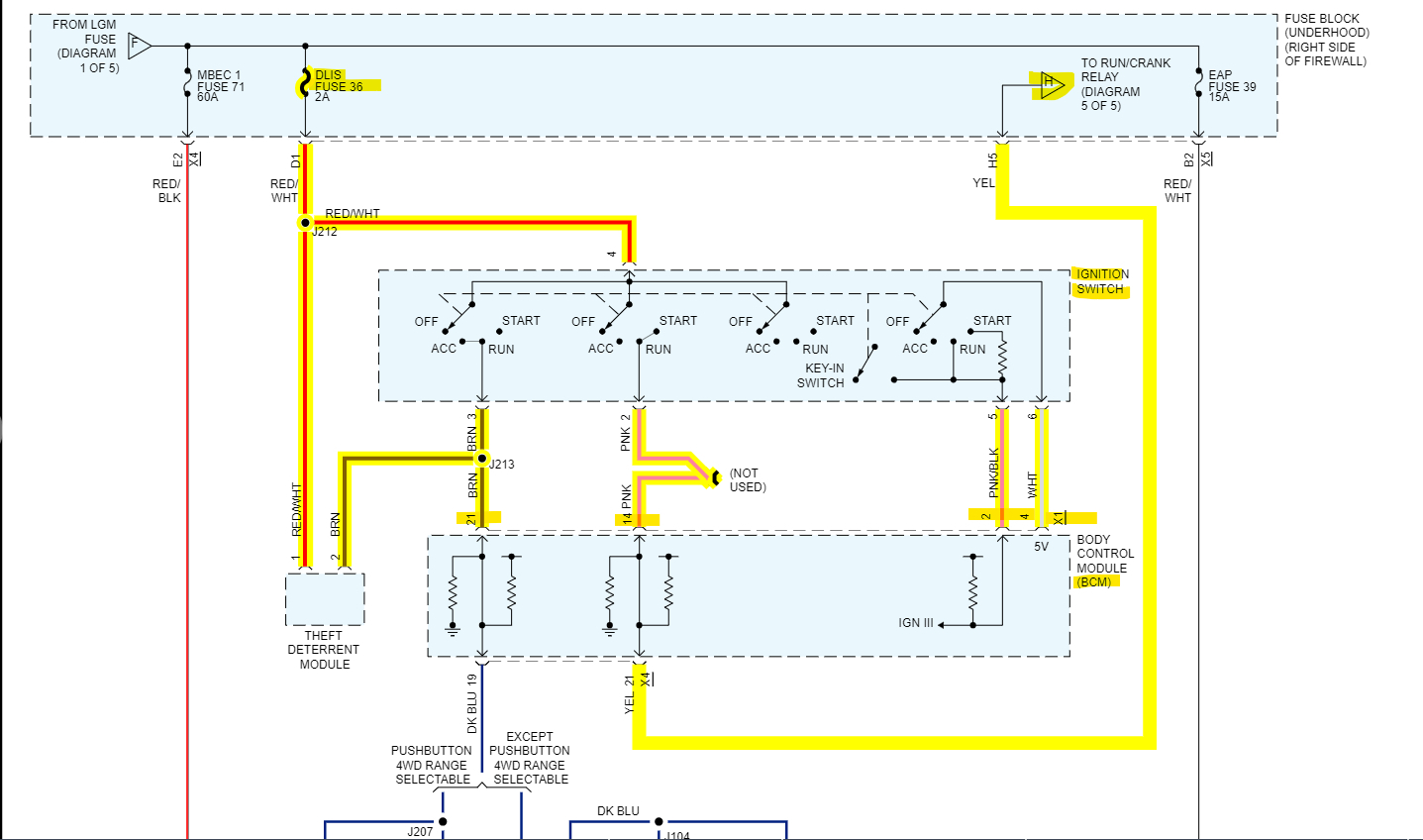
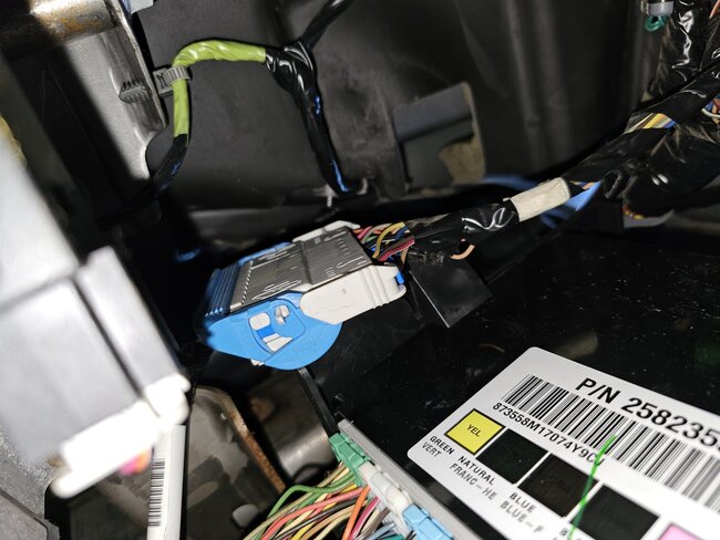
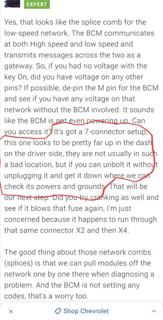
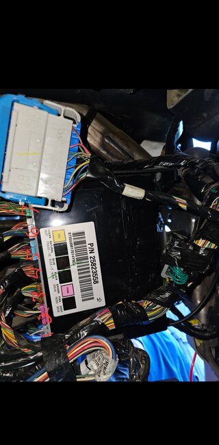
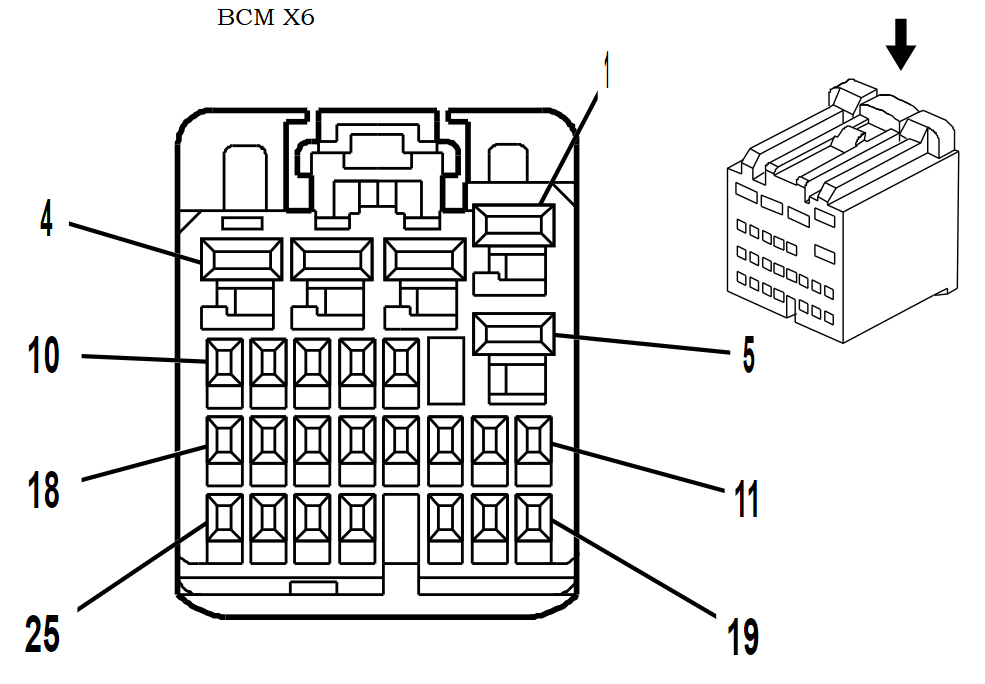
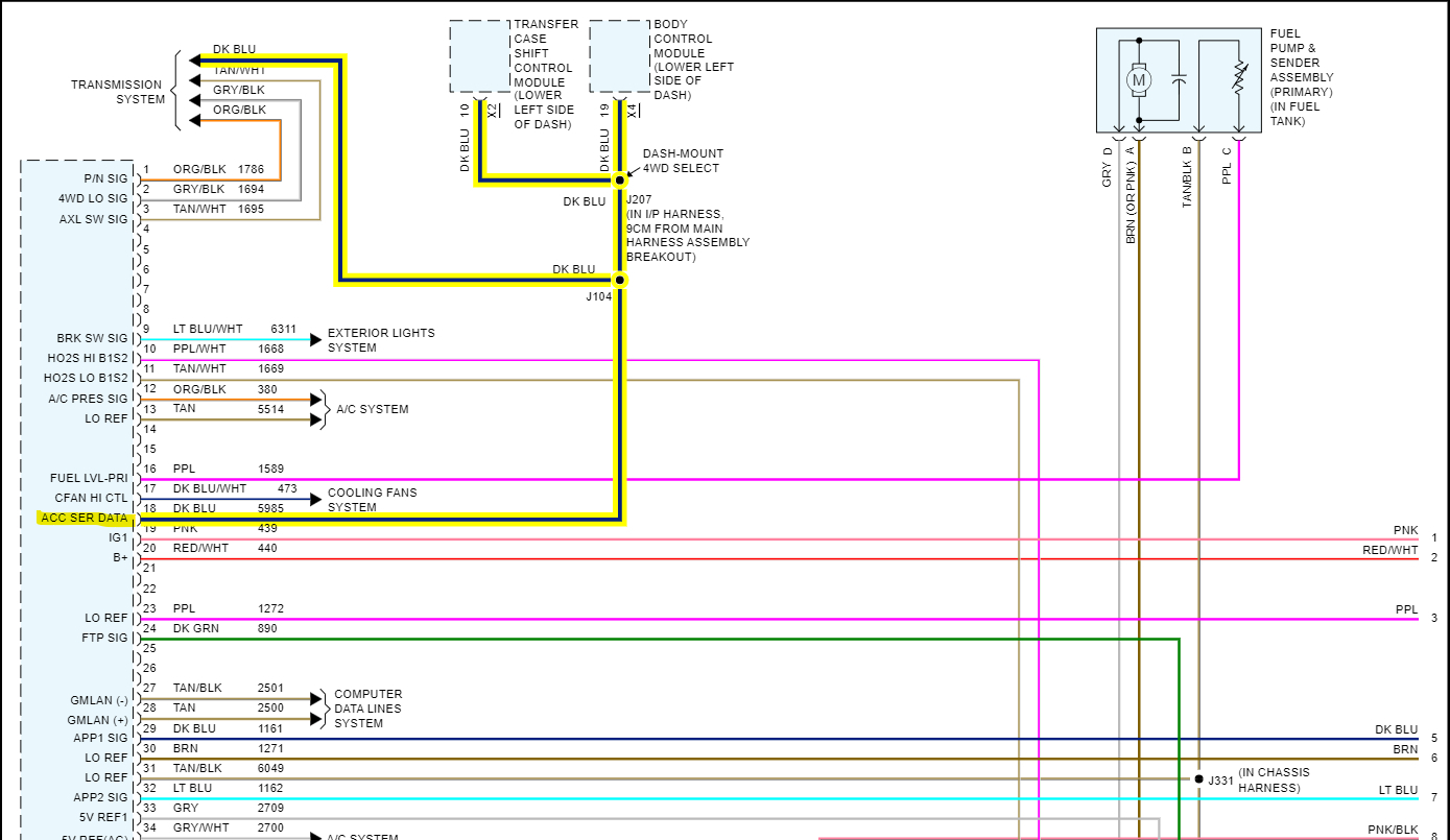
Yeah I havent looked into the transfer case module too much yet, but yes pin 10 darkBlue wire should be battery voltage. Were you reading exactly 5 volts? But I dont see any transfer case control module with that part number but Im going to run through these modules real quick, there are like 7 listed for this vehicle, I want to make to make sure the dark blue wire youre testing is not just a 5 volt reference, but in the mean time Ill post the BCM diagrams for you to check that since it will take awhile,

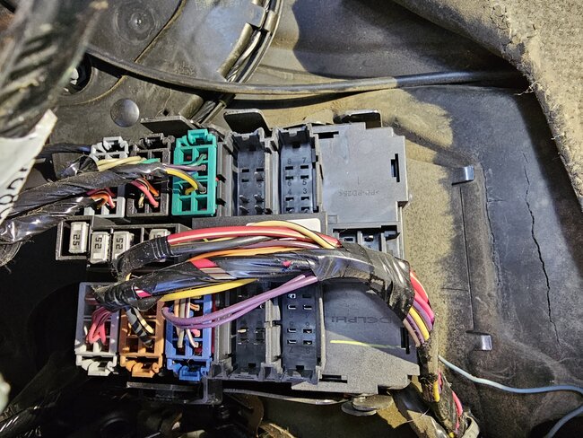
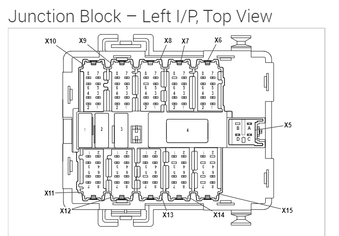
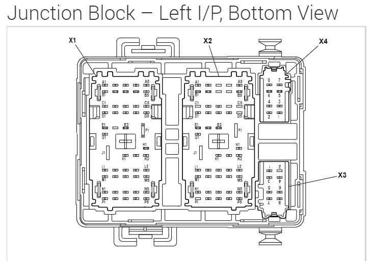
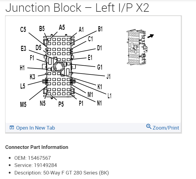
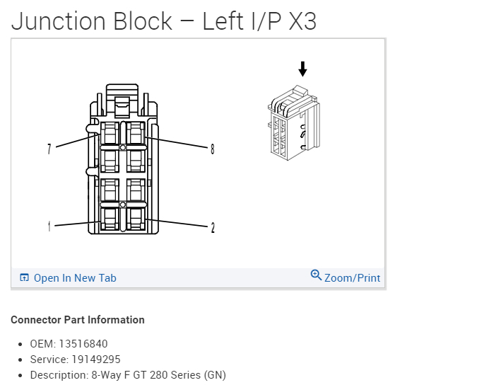
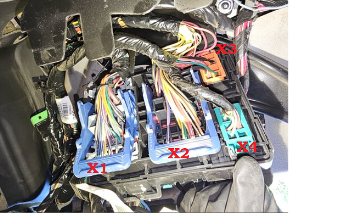
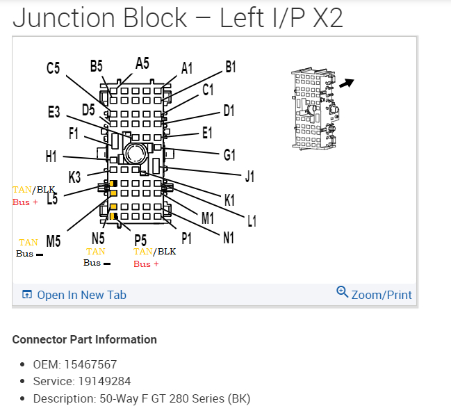
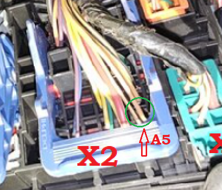
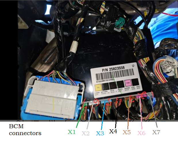
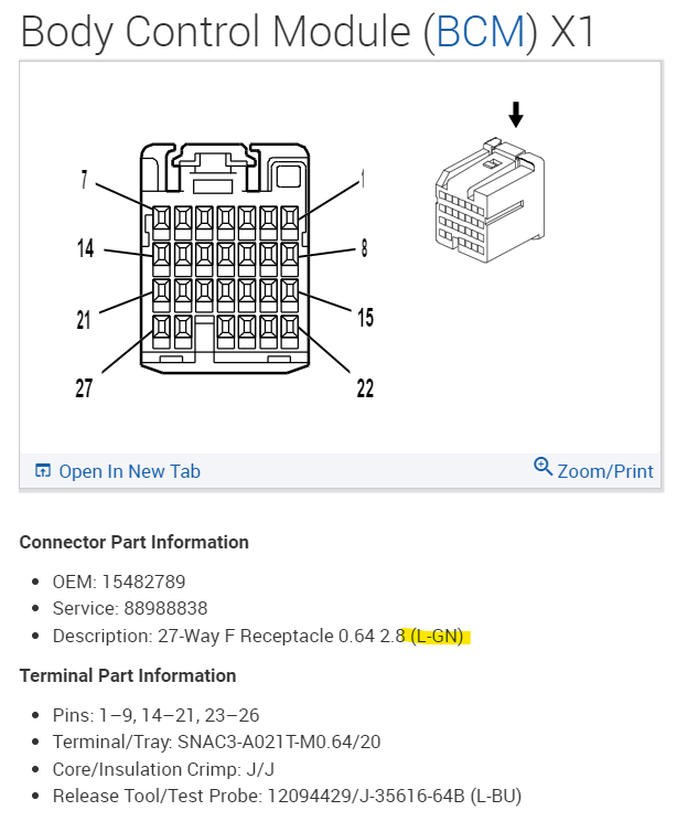
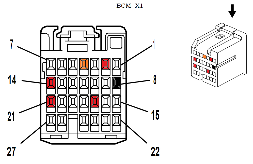
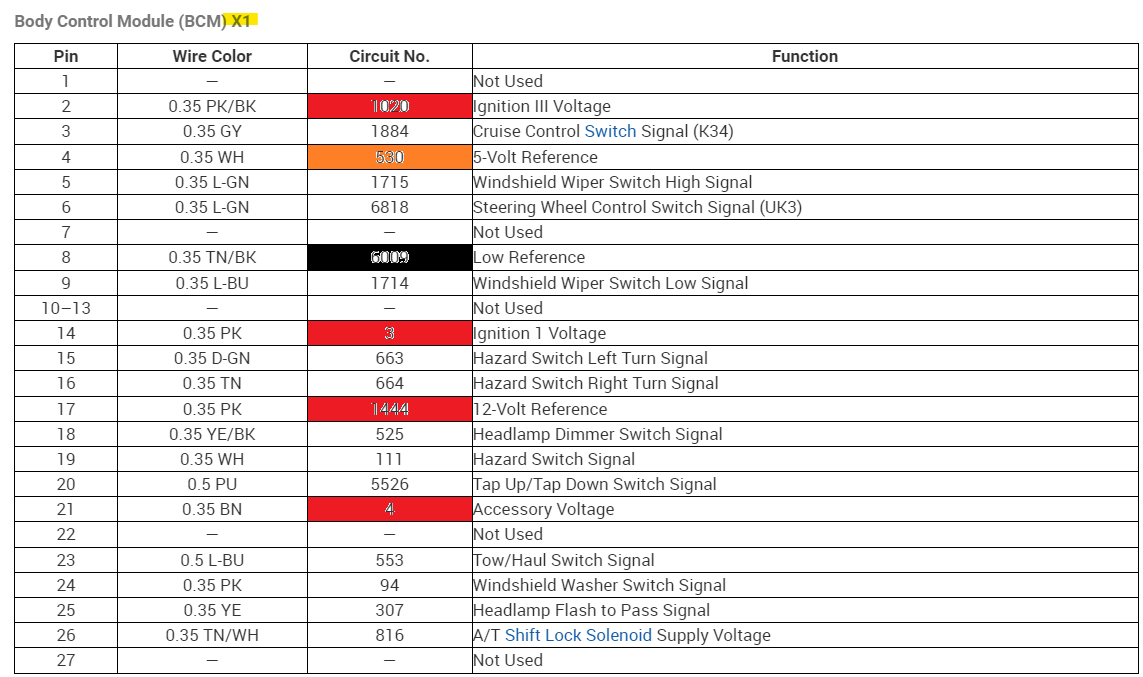
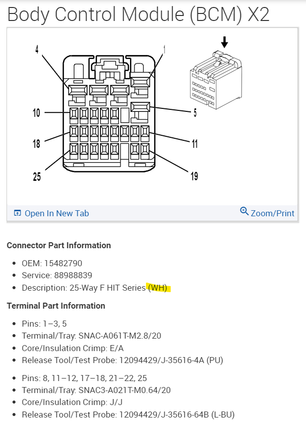
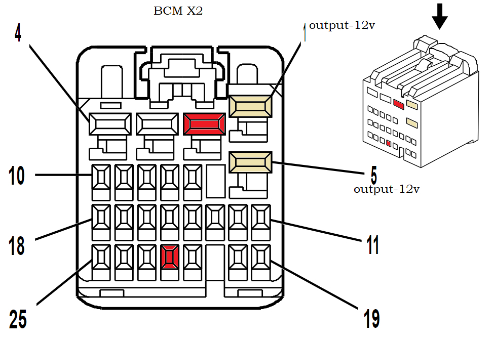
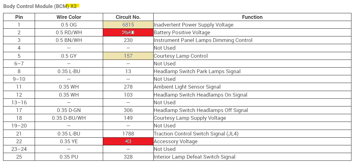
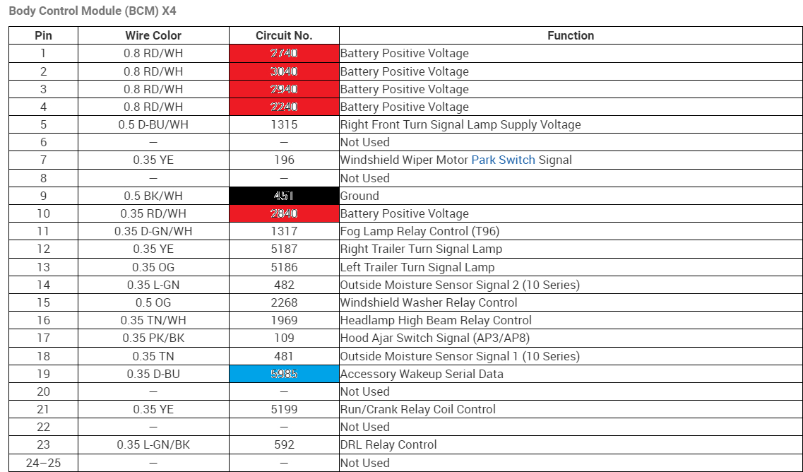
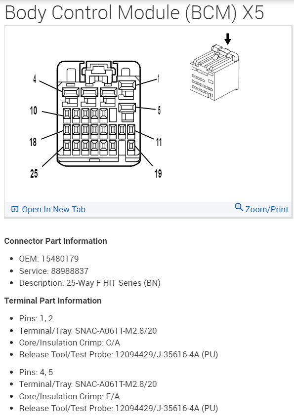
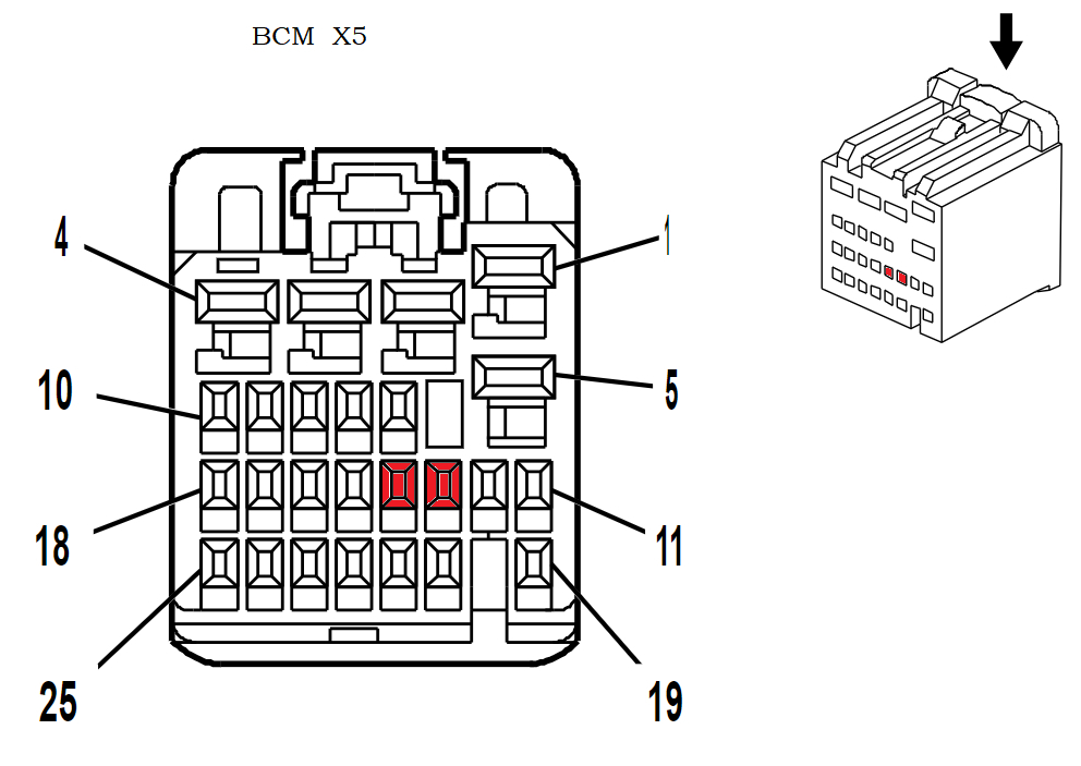
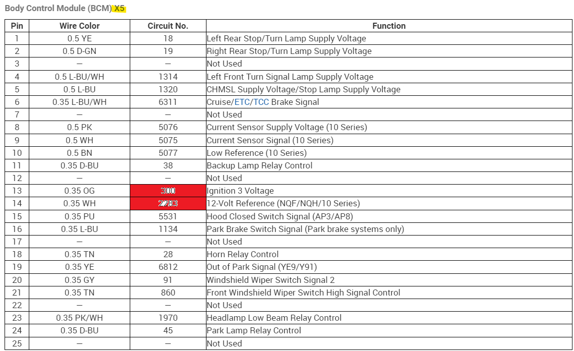
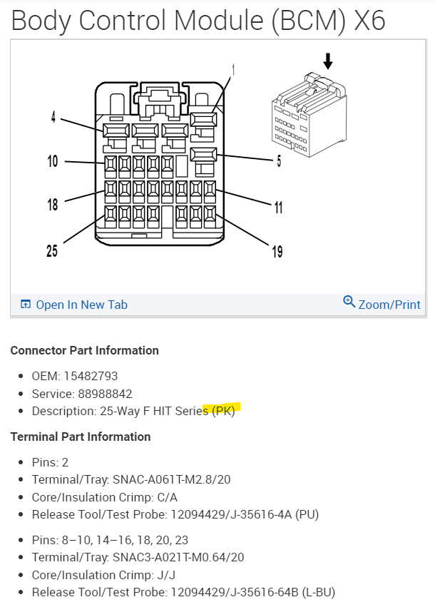
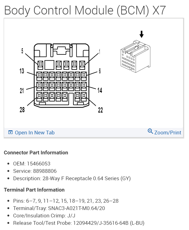
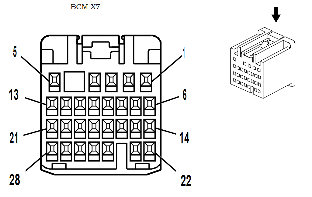
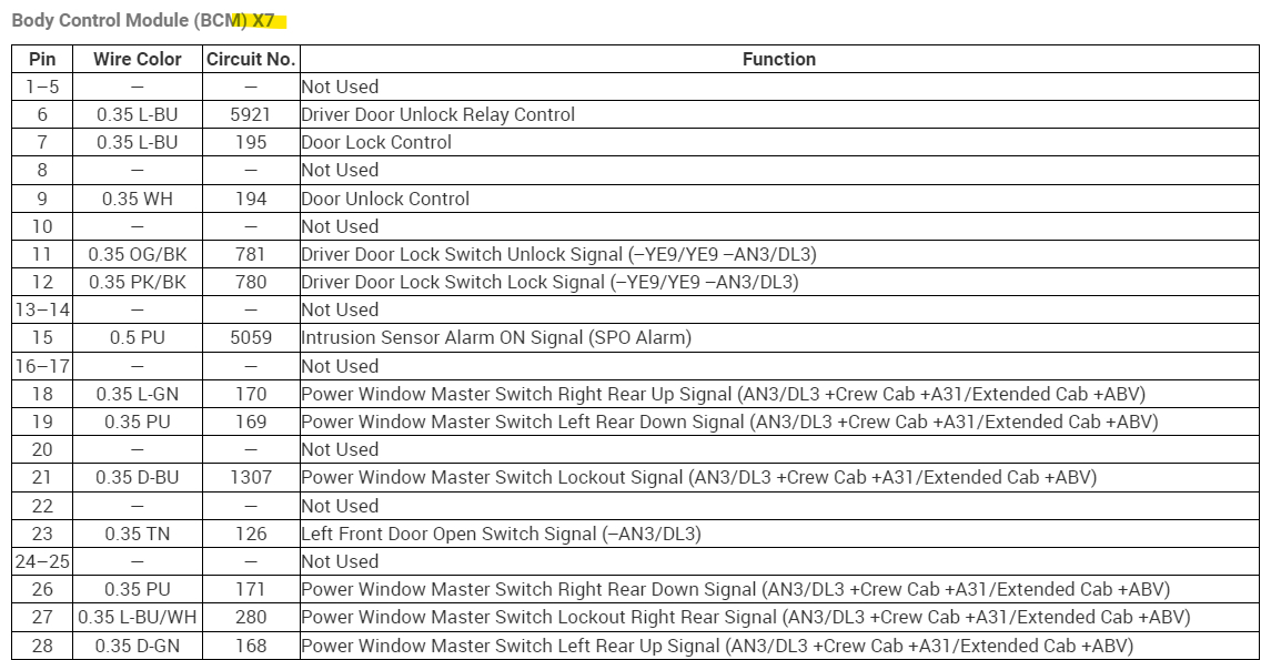
Now X6 and X7 didnt have any relevant pins we needed to check, but I included them anyway so you would have them, but take your time and go connector by connector. Most of these are power inputs with a couple Reference Outputs, such as a 5vRef and a 12vRef.

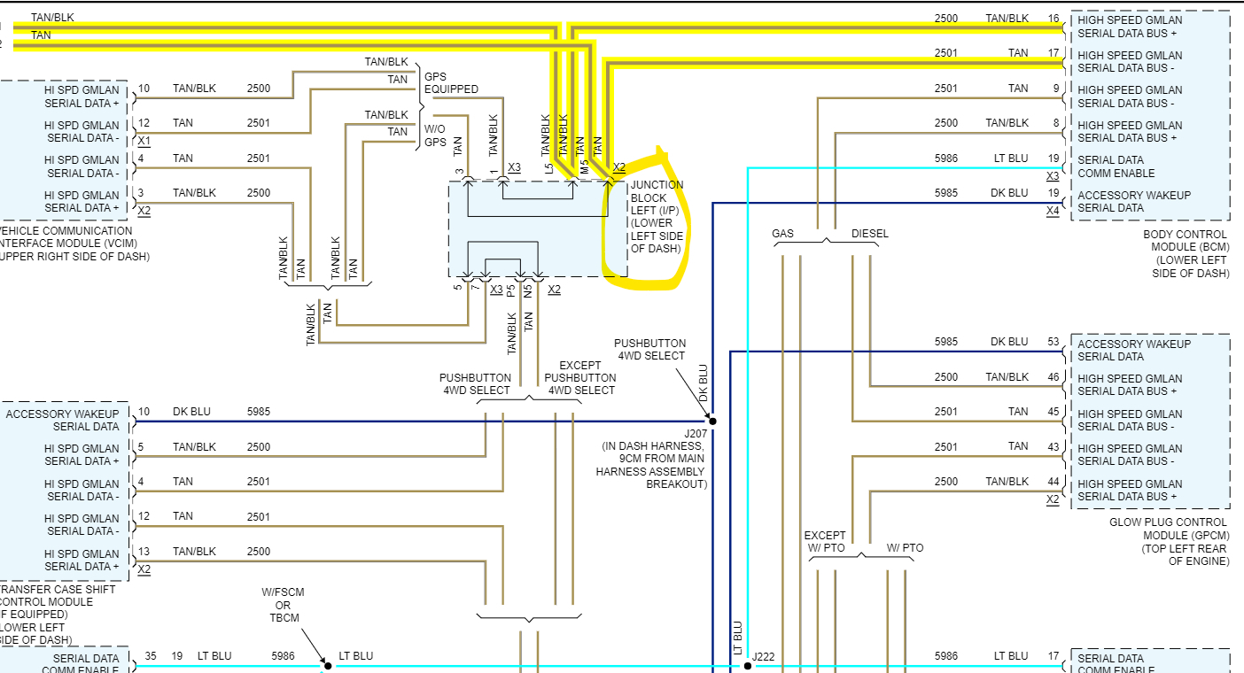
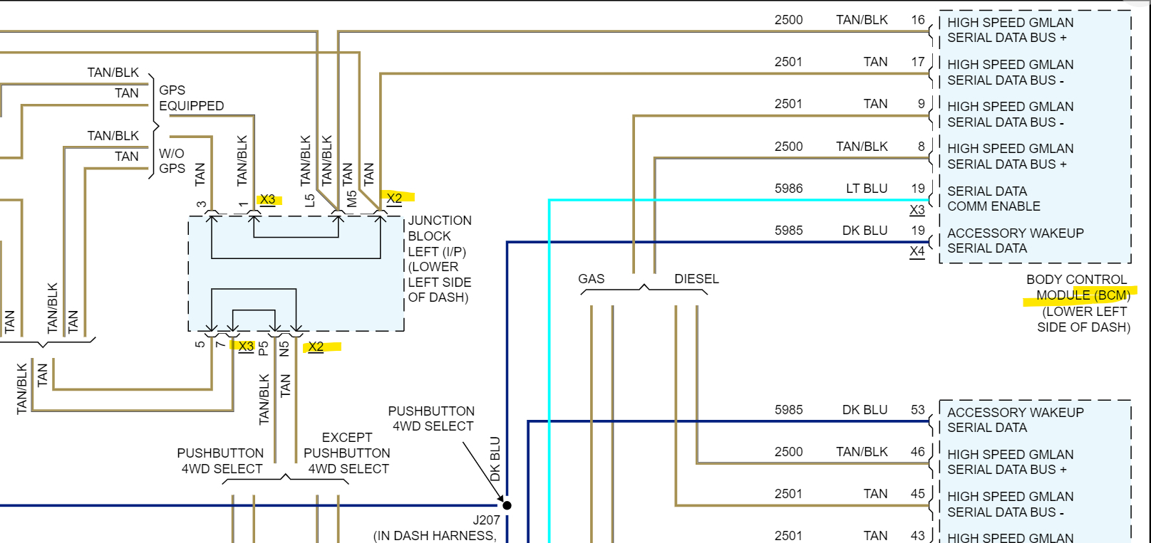
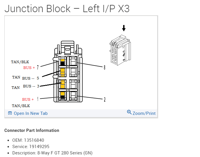
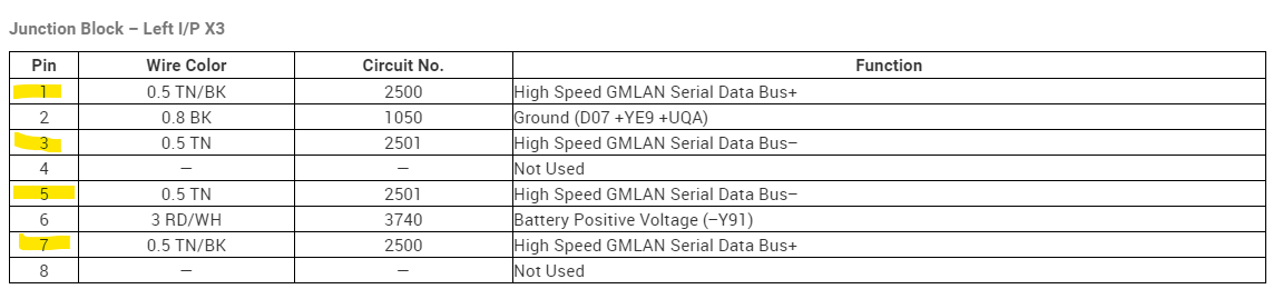
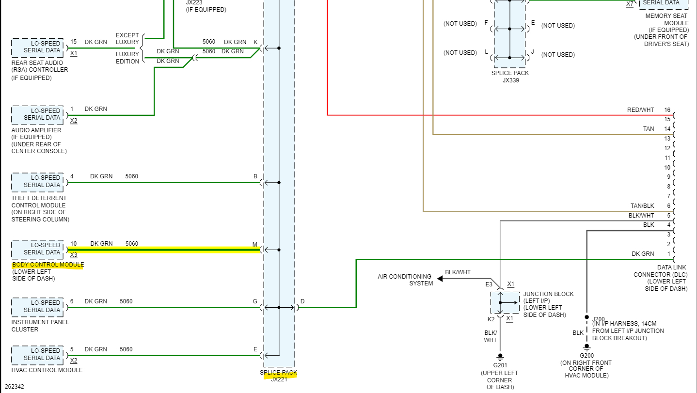
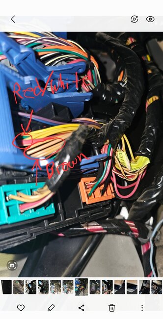
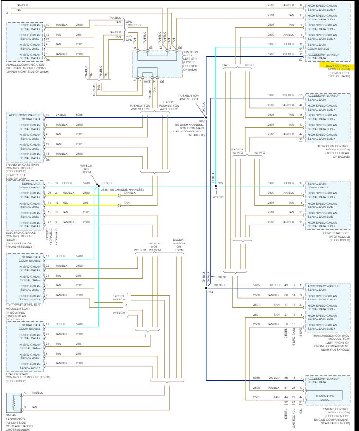
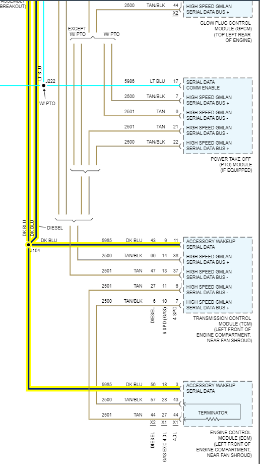
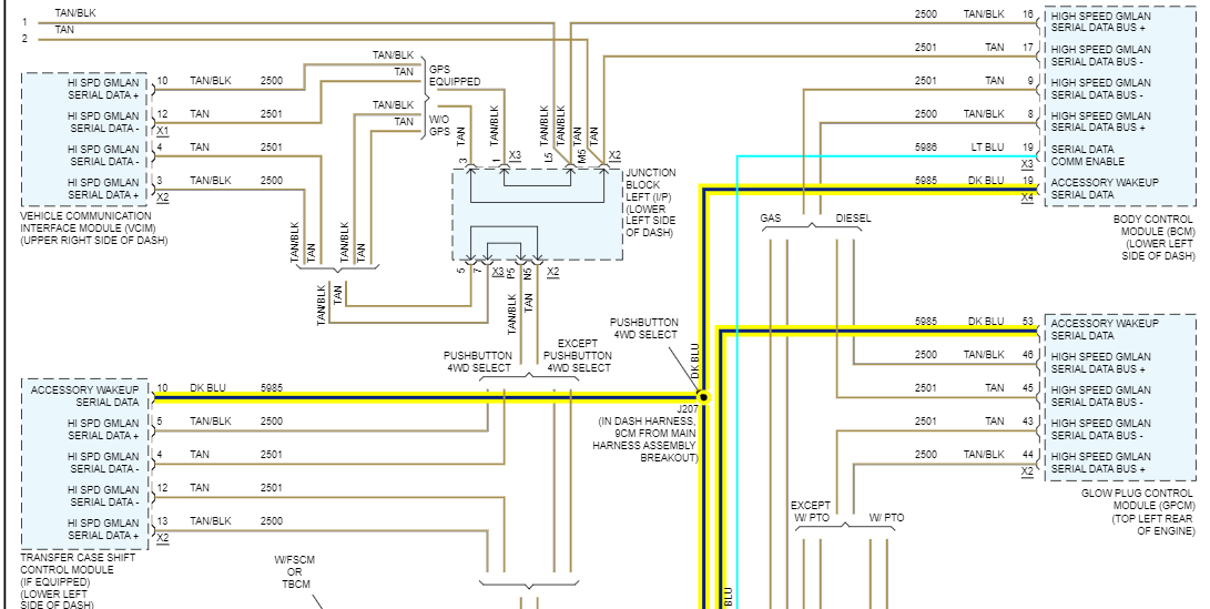
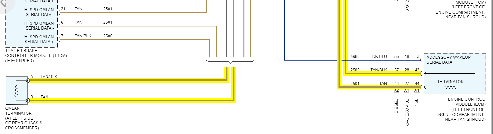
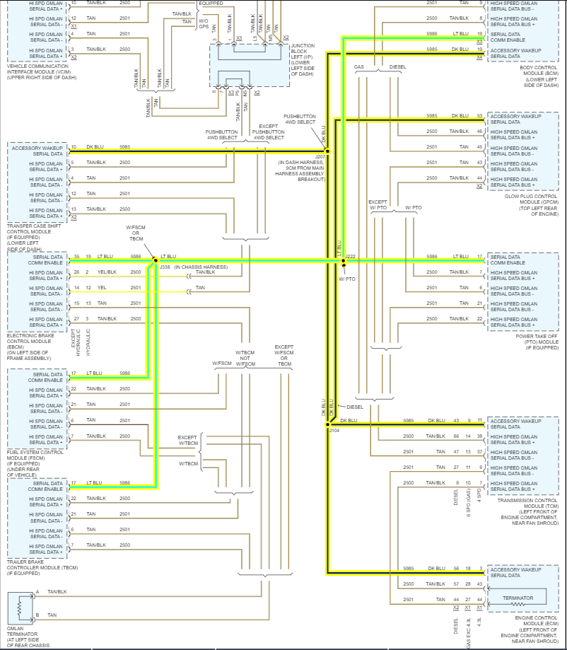
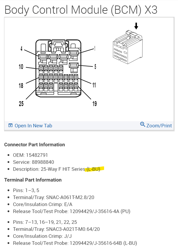
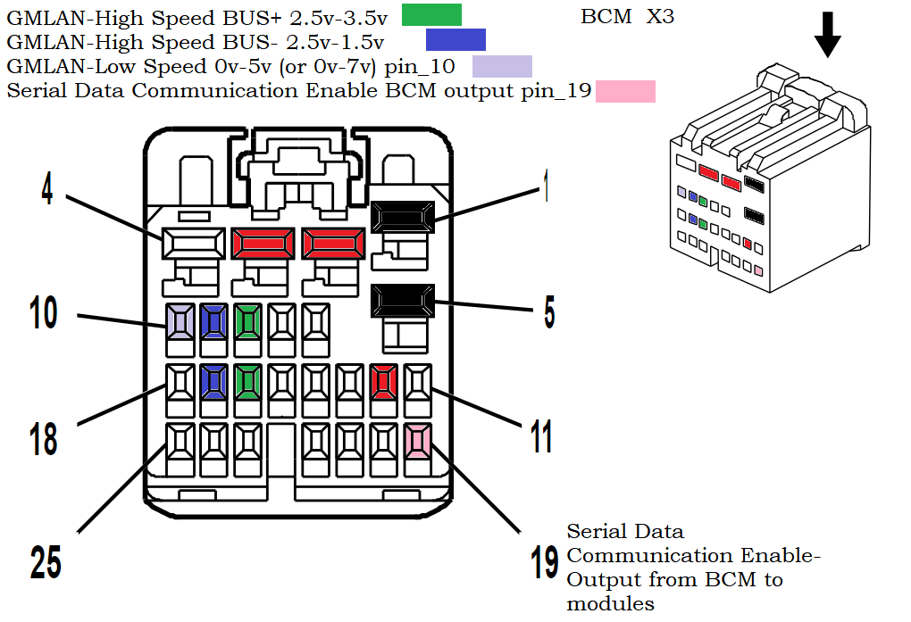
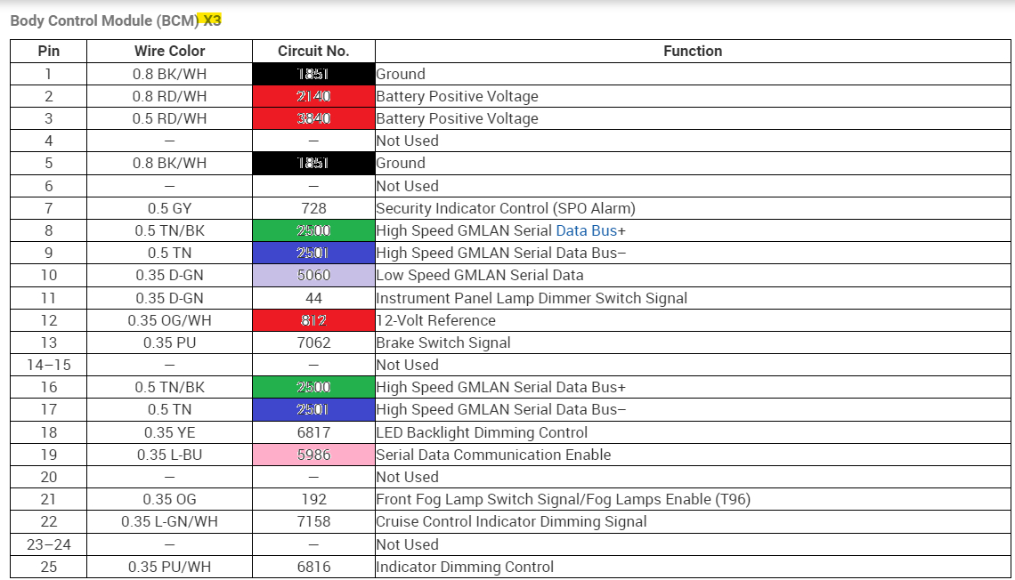
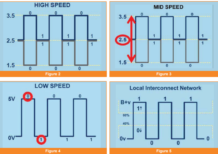
When you get to X3 the fun begins, thats the connector which has 2 sets on High Speed GMLAN wires, I marked them both Green for Highspeed+ and Blue for Highspeed-
but as you can see in the 23rd diagram, where its labelled "HIGH SPEED" those sets of wires are a "voltage differential" signal, thats what a CANBUS network looks like on a scope.
With a bias 2.5volts in the middle.
I put the voltage readings you should get for each, Check each of those wires with one meter lead on ground and the other on the High+ and then the High- wires.
So the High Speed Bus+ should be a 2.5v to 3.5v, the High Speed Bus- should read 2.5v to 1.5v. Its 2 signals that basically mirror each other, thats the easiest way to explain it right now. They will be a twisted pair of wires and that is to help shield them from interference.

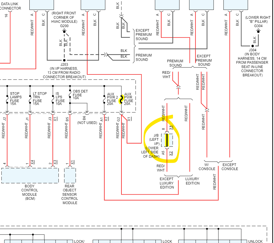
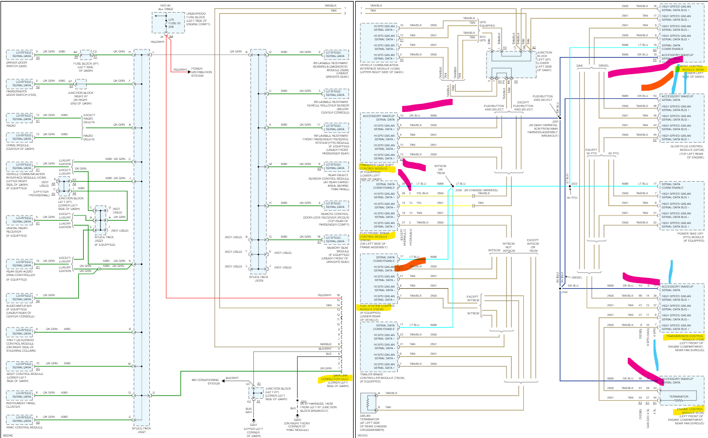
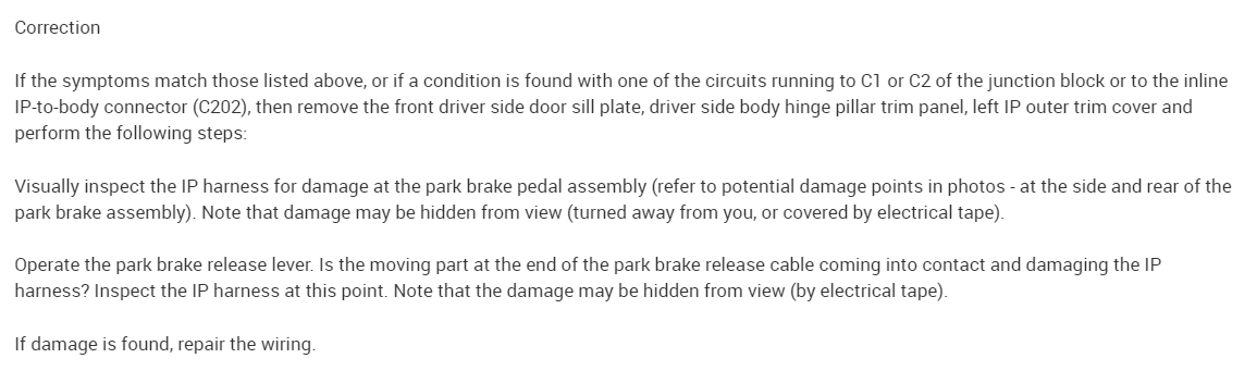
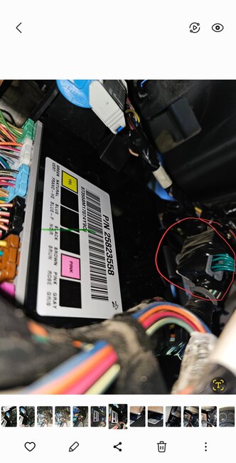
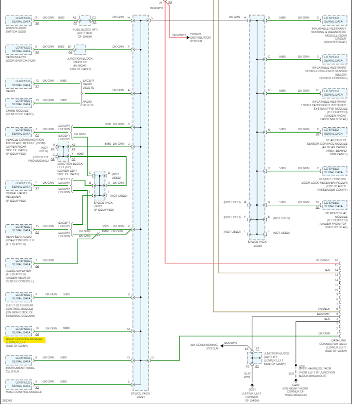
Now pin 10 of X3 is where the BCM acts as a Gateway to the GMLAN Low speed network, I colored that is Violet. It should be a 0v to 5v signal. The 24th diagram shows all the modules on the Low Speed network, they are the ones that have that Green wire you saw when checking the comb/splice under the drivers side dash.

So that leaves us with the Lite Blue Serial Data Comm Enable signal that you already checked, I dont see an exact voltage for that yet. Ive been looking but it took me forever to do all these diagrams But I dont think its supposed to battery voltage, but I might be wrong on that.
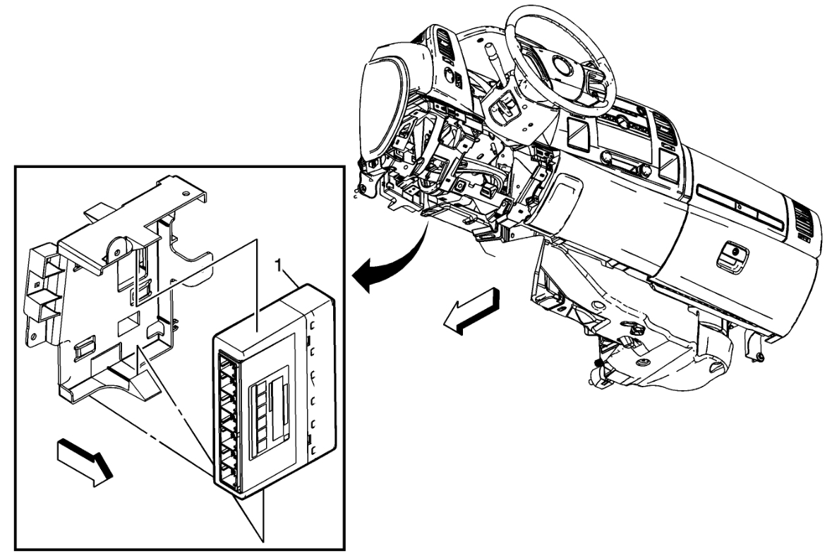
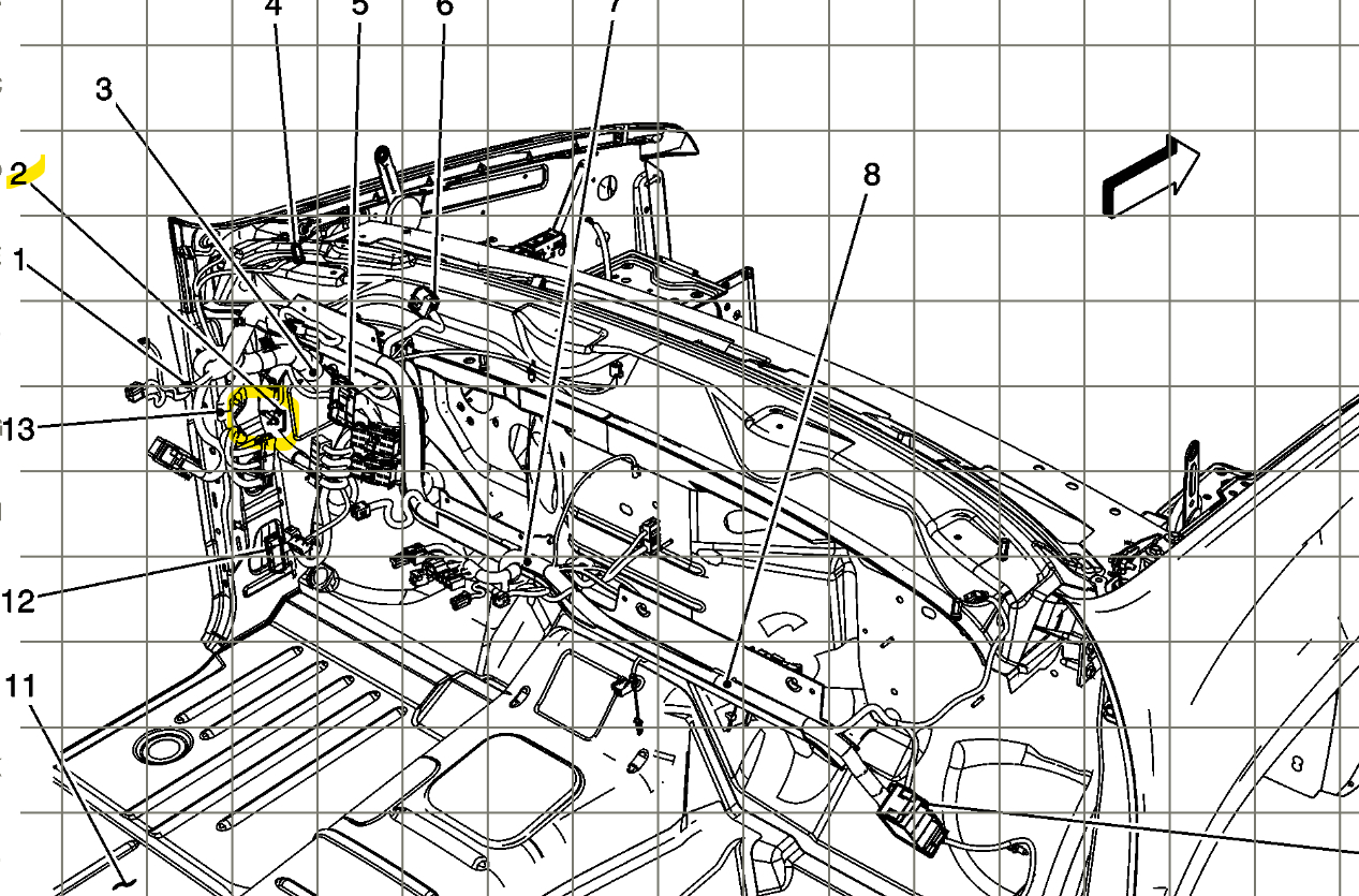
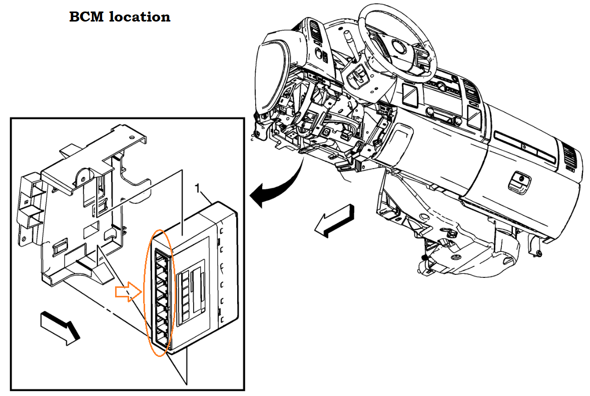
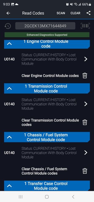
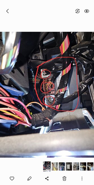
So you can at least get started on the BCM connectors, you'll need the key On, and I dont know if you have a battery maintainer to keep a charge on the battery while doing this testing. Its always good to have one on the battery to prevent low voltage issues while testing like this. Ill verify the Transfer case module voltage you read. And get back to you, as well as the Enable voltage. But I think that if the Enable was incorrect you wouldnt be able to pull any codes at all, that again Im not a 100percent sure on.

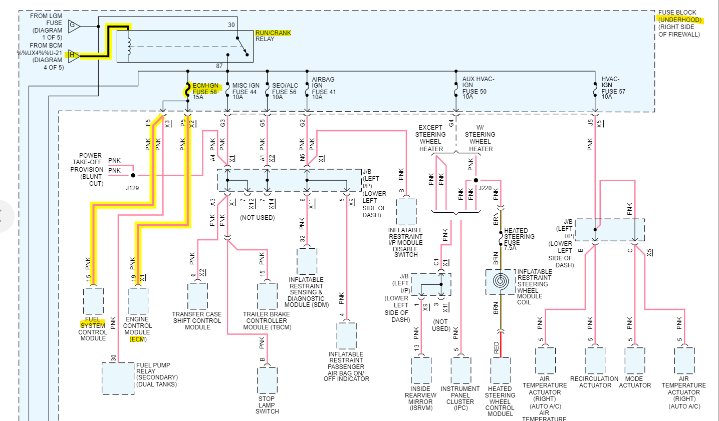
The scan tools can communicate on different networks through the DLC. You'll have to check all these plugged in of course, when checking the Powers and Grounds, if this is possible, have a lead to Battery Negative to verify the circuit is making it all the way back to the Battery.
Sorry for the long post. Keep me updated when you get a chance. But no rush I always have plenty to do.
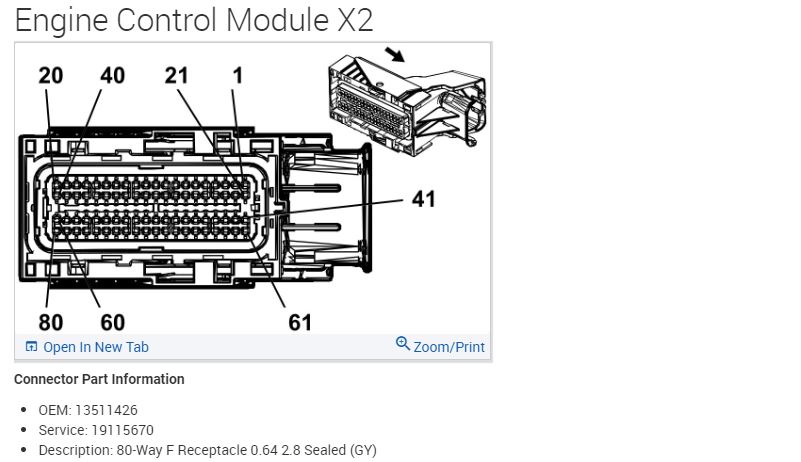
Aug 19, 2023 at 7:44 AM
Avatar
AL514
  • CERTIFIED EXPERT
  • 5,465 POSTS
You are correct, the transfer case module should have the same Accessory Wake Up voltage on pin 10 dark blue X2 connector, why it only has 5 volts I'm not sure, What you can do, is with the key Off, unplug that connector, turn the key On and recheck that wire, does it still read 5v or does it jump up to Battery voltage. If it does jump up, let me know.
I don't know if you'll be able to access the ECM connector X1 without unplugging it, but I'm wondering if that Accessory voltage is the same at the ECM as at the transfer case module, because the ECM is further down the line.
These are the connectors for the ECM, X1 pin 18 is the same Dark Blue wire, if you can check it good. There is a splice that Accessory Wakeup Serial Data comes from, and we should see if the ECM is receiving that same 5volts
Even if you can pierce the ECM X1 wire to check it without having to pull everything apart, and seal it up afterwards. I put in the X2 connector here as well for reference, so you can ID the X1 easier.
I'm wondering if there is a bad splice here, or if that wakeup circuit is shorted to battery voltage somewhere.
Aug 19, 2023 at 8:35 AM
Avatar
JAVIERMLNDZ
  • MEMBER
  • 51 POSTS
I'll do that as soon as finish cutting the grass.
Aug 19, 2023 at 9:11 AM