ignition coil primary male spade + terminal voltage?

2003 CHEVROLET MONTE CARLO
157,000 MILES • 3.8L • V6 • 2WD • AUTOMATIC
Avatar
BRUCEDUNCAN
  • MEMBER
  • 29 POSTS
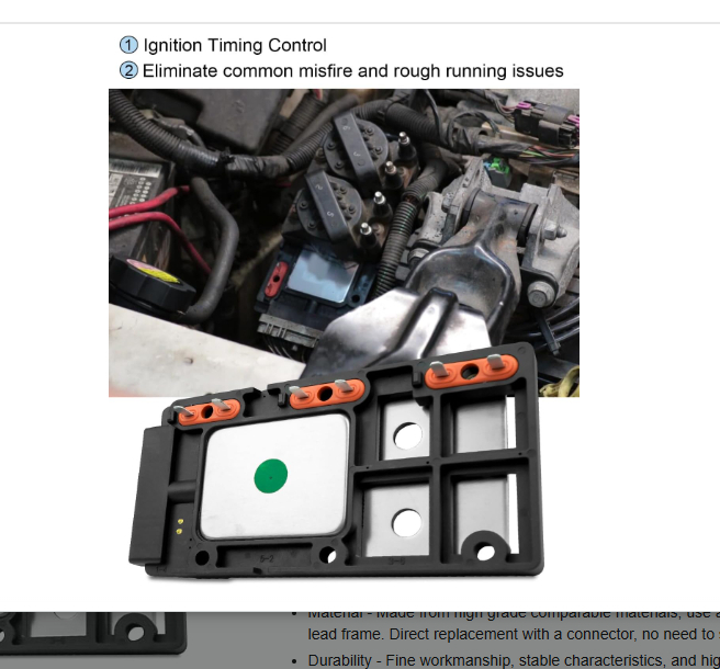
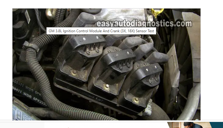
If you remove the coil from the Ignition Control Module it exposes the primary + and - male spade terminals.
I was told on a mechanic site www.autocodes.com that the + spade should have 12 volts key on engine off. my car has less than a volt on all three coils. the 2/5 coil had 18 to 20 mv. the 6/3 coil had4 to 5 mv. the1/4 coil had 16 mv.
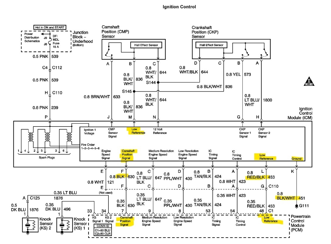
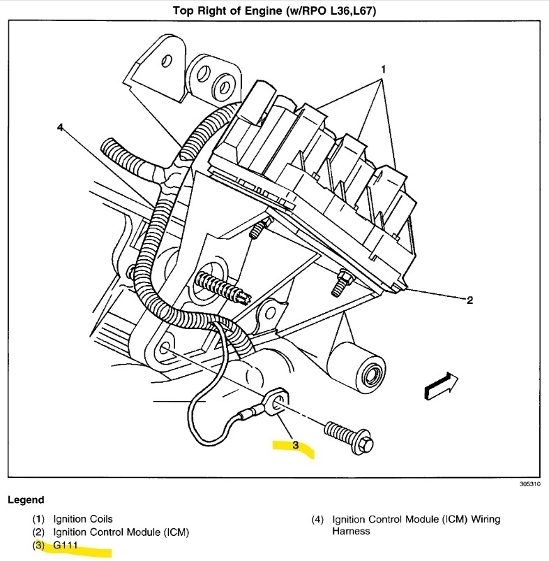
I grounded the multimeter to battery post - post and primary coil - terminal. I got the same readings at both locations. The primary coil - terminals have less .2 ohms resistance or less to the icm case. The icm mounting base has good ground to the block and the battery - post.
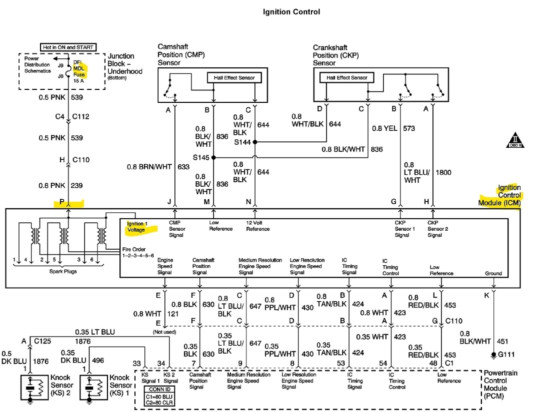
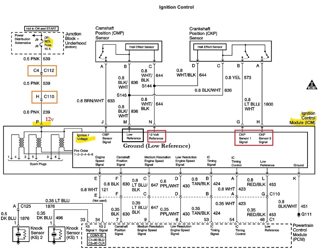
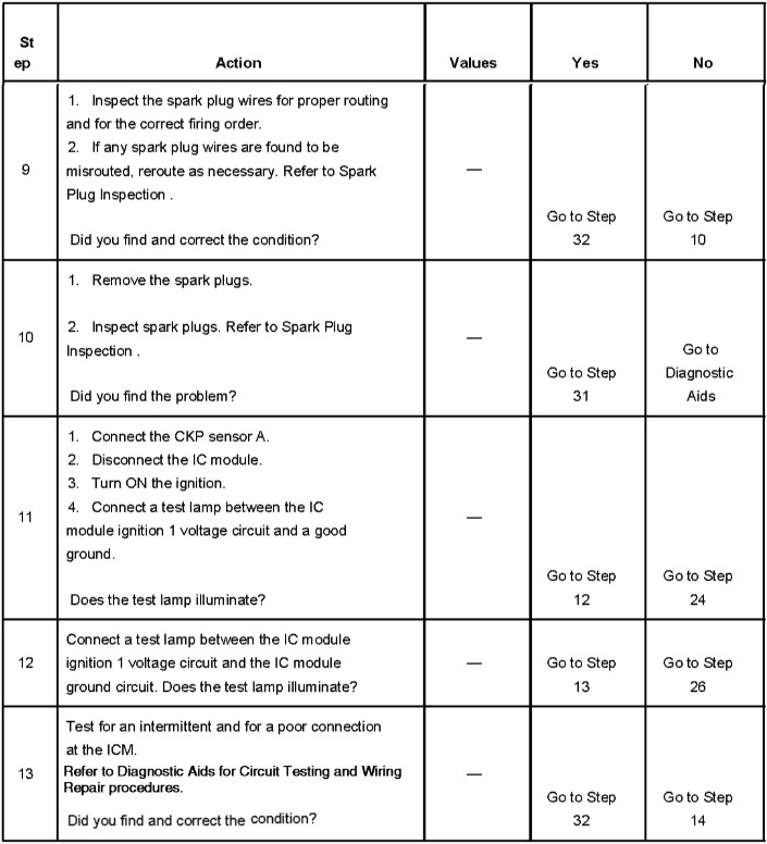
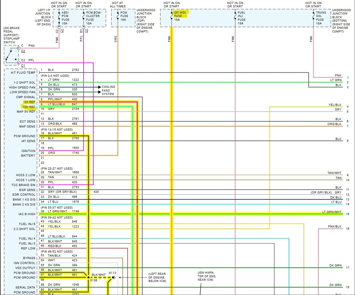
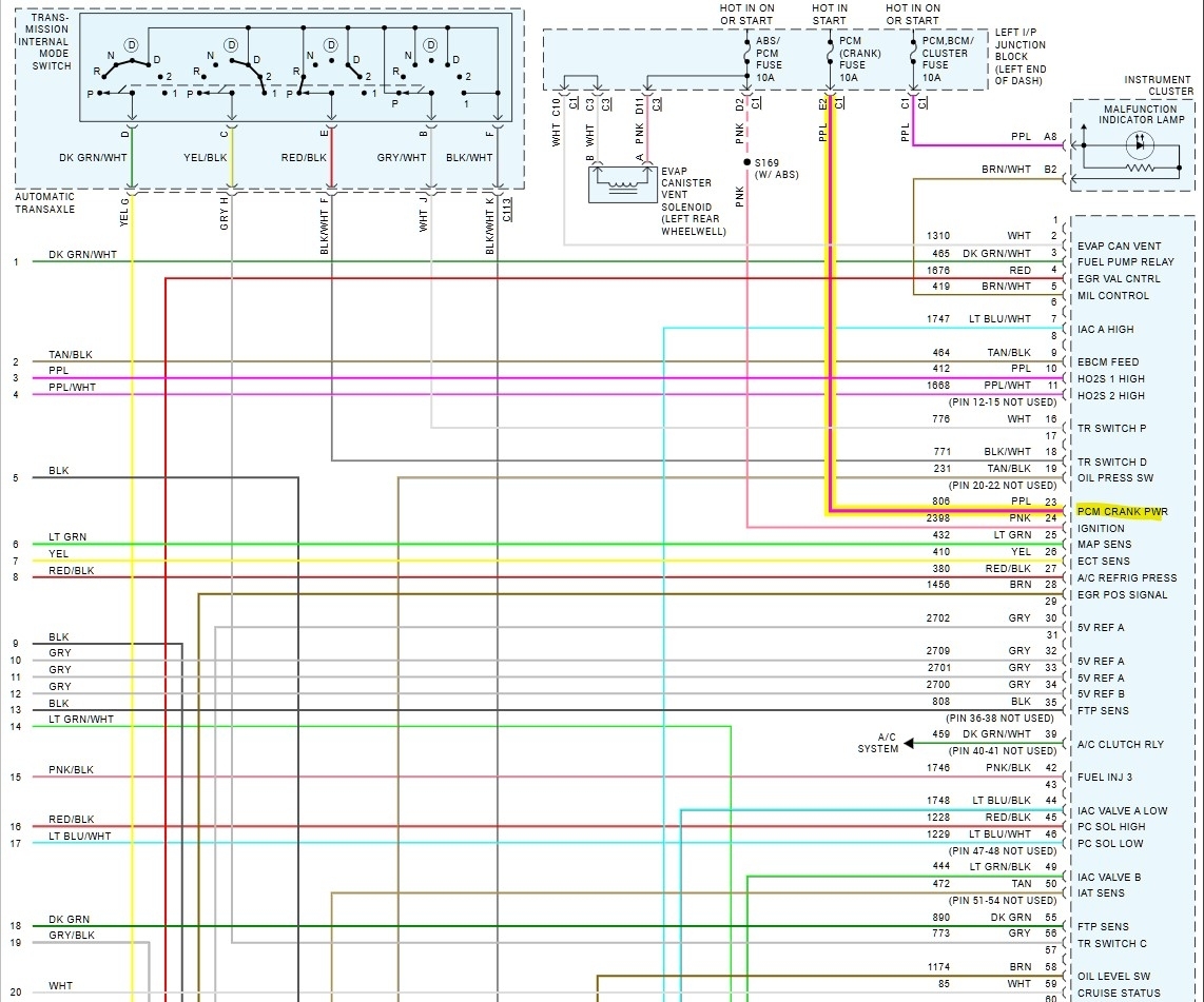
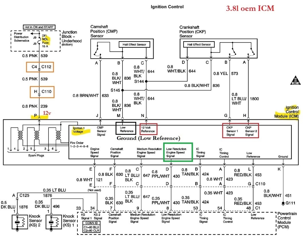
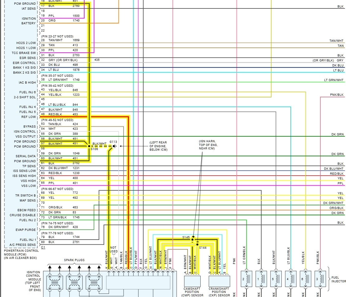
I put my multimeter on the icm harness terminal p pink power and terminal k black/white ground wire which goes to the block and got more than 12 volts. I loaded the circuit with a test light and got over 12 volts. I was told the pink wire feeds the coils.
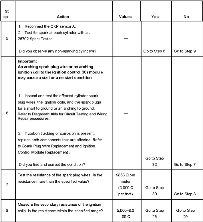
All 3 coils have no spark. I put my test light to battery post + and primary coil - terminal and got a bright light. While cranking the light went out. No icm triggering.
I put my test light to primary coil + and - while cranking, no blinking hence no triggering.
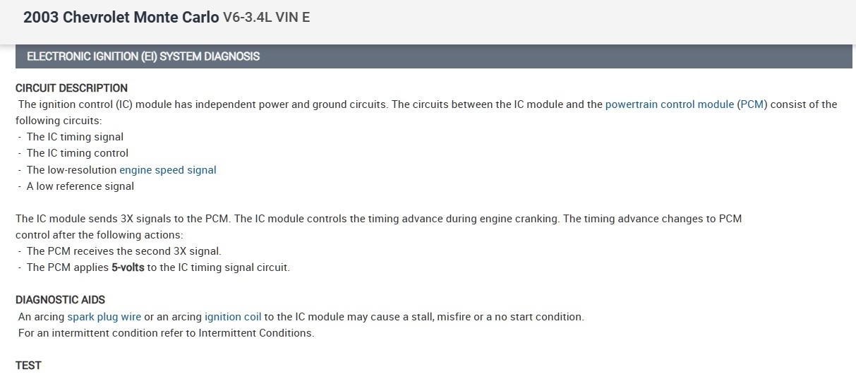
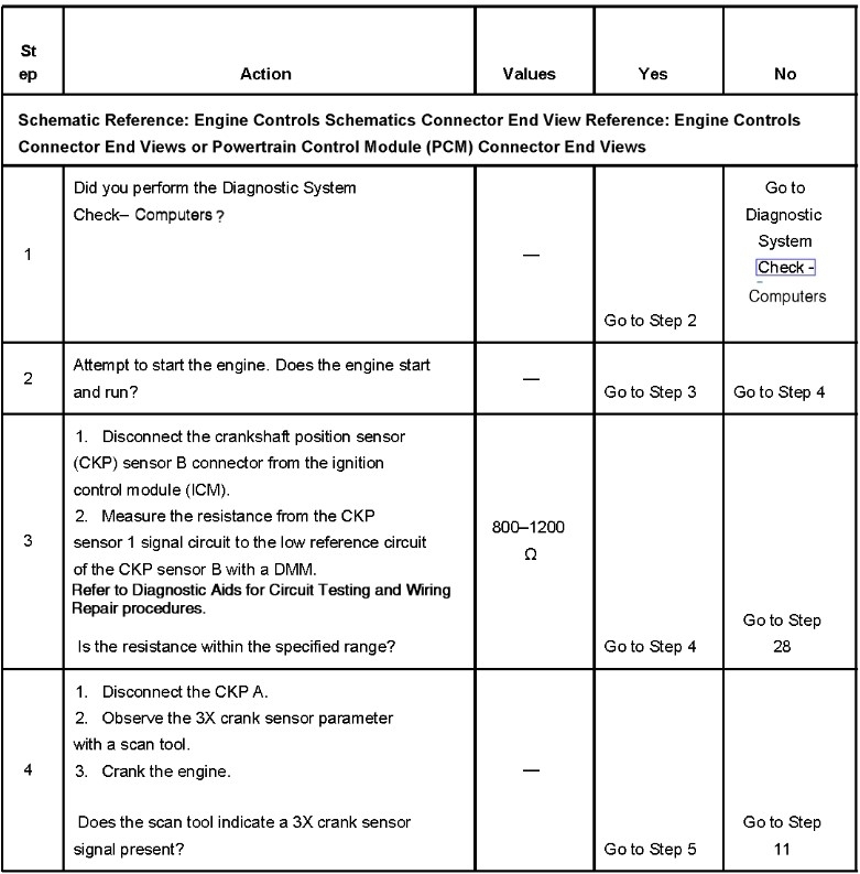
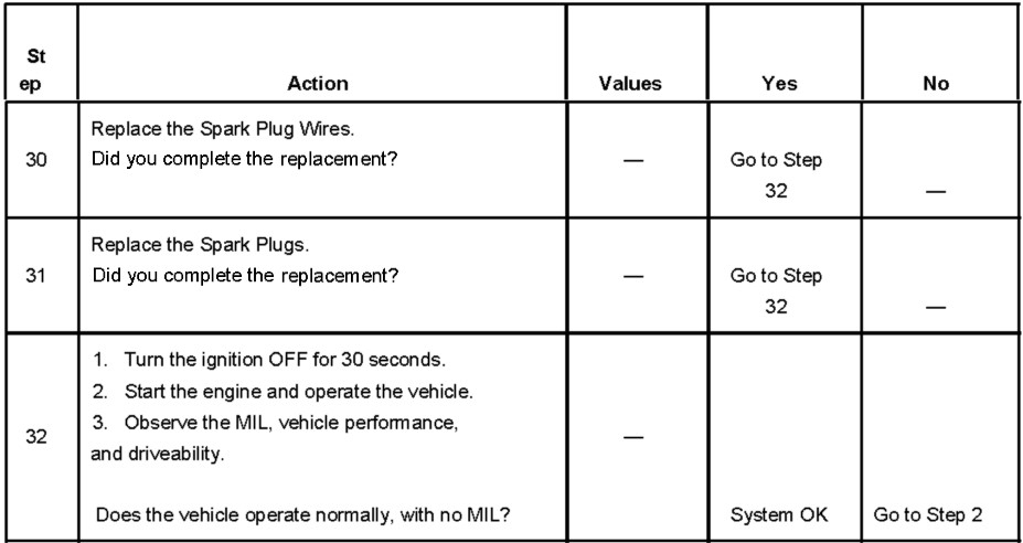
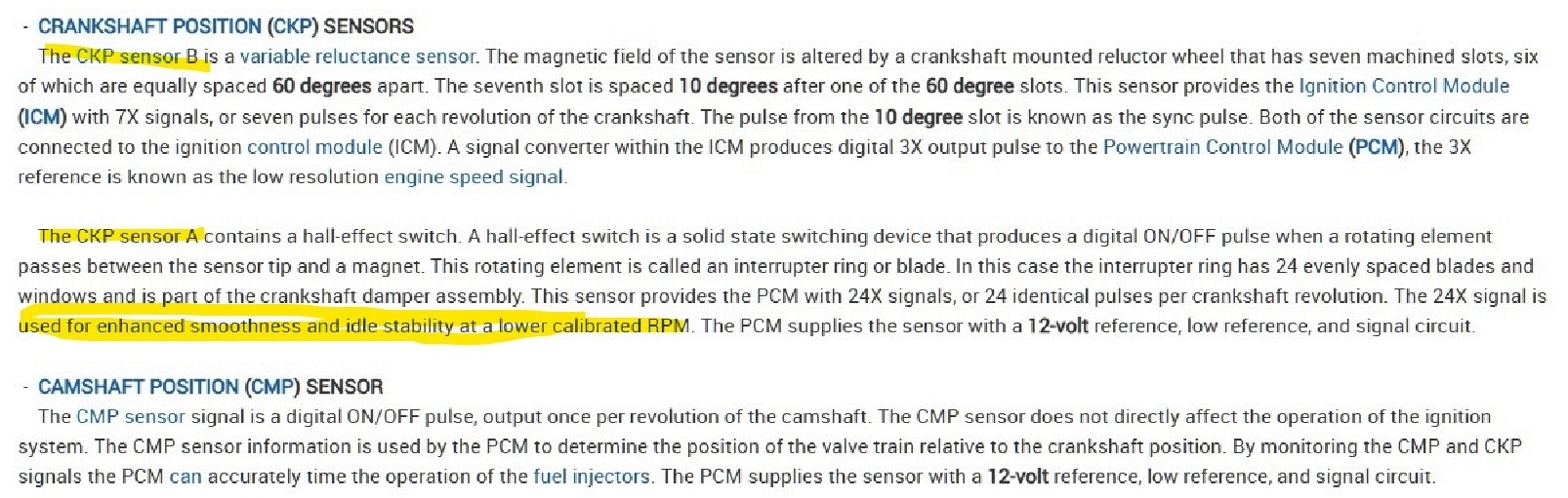
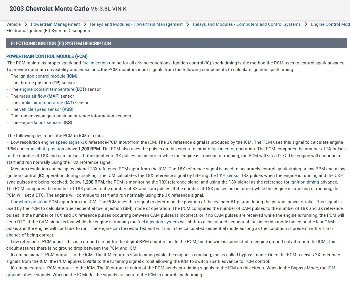
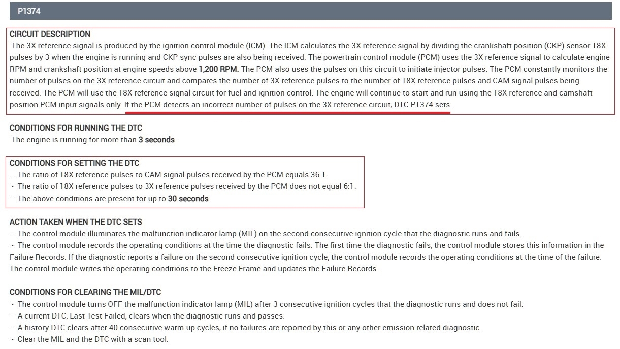
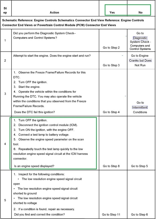
My car was bucking and jerking in park and blowing a little black smoke. Trouble code P/1374 set. crank sensor reference circuit. 2 days later I had no spark on any coil.
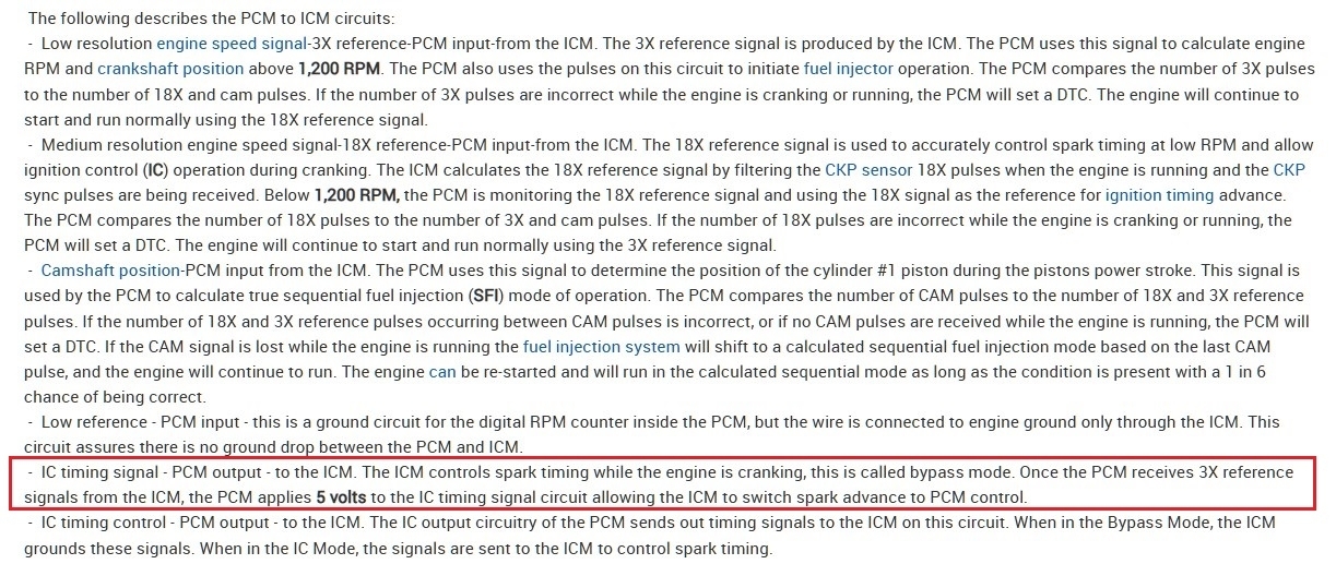
My 3x rpm on my scan tool showed 0 rpm while cranking once and on many, many retests i have a rpm signal.
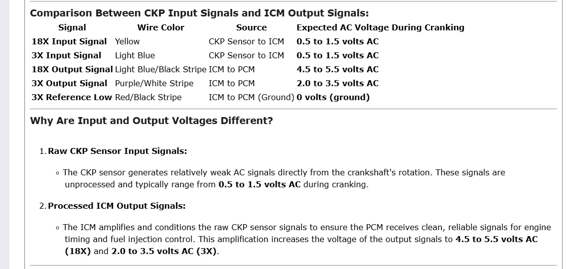
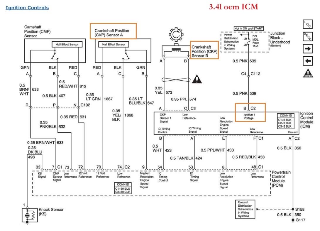
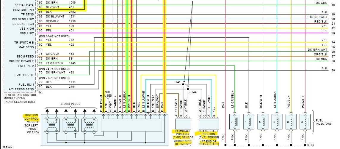
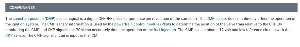
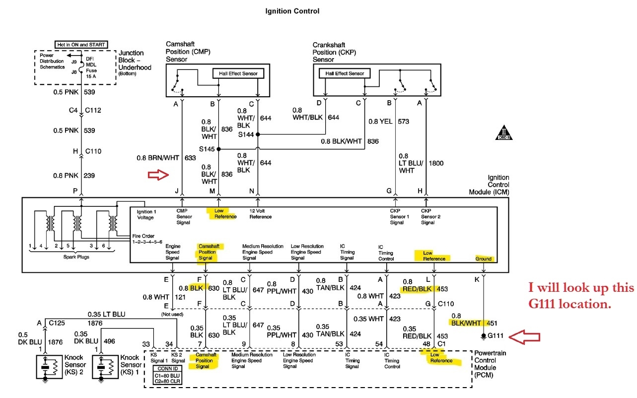
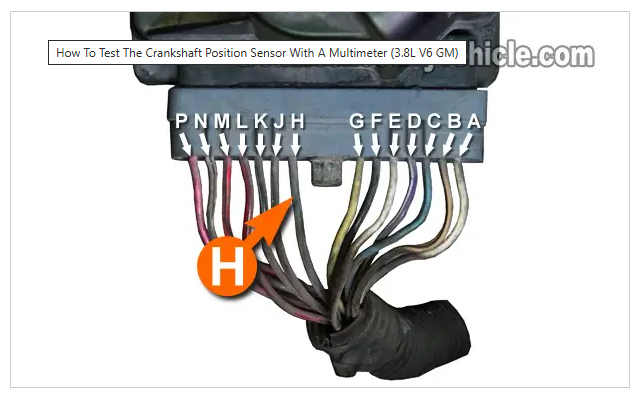
I then measured the 18x crank sensor signal wire going into the icm terminal g yellow wire. I measured at the icm with a multimeter and it shot up 3.5 ac volts while cranking with no minimum voltage. I was told my multimeter is too slow to read it. On the 3x signal wire i got 1.7 to 2.8 ac volts while cranking terminal h light blue/white wire.
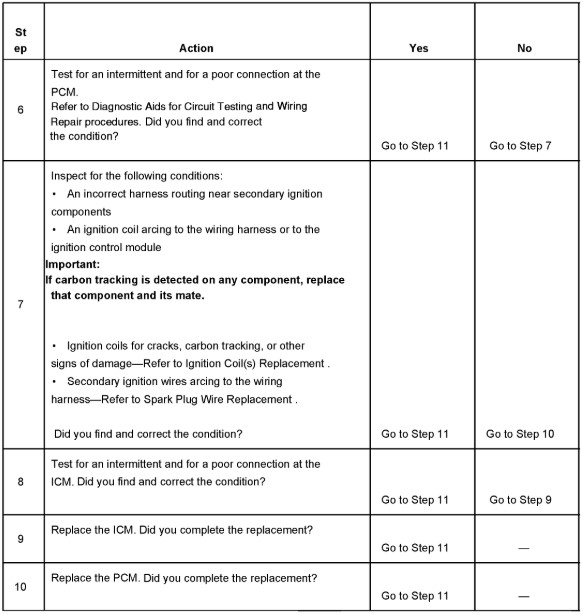
I was told the coil primary - terminal switches on and off to do the coil sparking and the + terminal has 12 volts all the time. It sounds like i need an icm.
I may or may not check my 18x and 3x voltages coming out of the icm. I may or may not turn the crank by hand and measure the crank sensor dc volt outputs. but i all ready have a rpm reading and crank sensor outputs.
To summarize should I have 12 volts on the coil primary + terminal. key on engine off.
I await your reply. Thanks a bunch, Bruce Duncan
Mar 20, 2025 at 8:28 AM
Advertisement
Avatar
AL514
  • CERTIFIED EXPERT
  • 5,465 POSTS
Hello, reading the service information on how the 3x signal is calculated will help. A multimeter is too slow to see the actual waveform the crank sensor produces, this is where using an oscilloscope is very effective and is needed on many modern vehicles, I'll post the service info on the code you are getting. The ICM actually produces the 3x signal by using the 18x crank signal. There is a testing flow chart for this code as well that Ill post along with the ECM/PCM wiring diagrams, so you have them if needed. A test you can do with the multimeter is to check that the cam or crank sensor wiring is not shorted to ground, by unplugging the ICM so the circuits are isolated, key off, you can check each wire of the cam and crank sensor for continuity to ground. I will check the OEM diagrams as well to make sure they are correct, but the wiring diagrams show that all the wires for both sensors go to the ICM, so you technically shouldn't have any continuity to ground on any sensor wires, if the OEM diagrams show anything different I'll post them as well.

Sorry I misread your post, the pink wire at ICM should read 12volts with the Key On engine off, and Ground on the black/white wire, as for power at each coil with them unplugged from the ICM, that I will have to check on, since the ICM has integrated circuits on it, with a code set like this, it may or may not power up the coils. But the wiring diagrams will help, the real issue here is if the ICM has failed or not, because it's responsible for calculating the 3x signal by dividing the 18x signal and outputting the 3x to the PCM which uses it for triggering injectors and engine RPM.
Mar 20, 2025 at 10:20 AM
Avatar
AL514
  • CERTIFIED EXPERT
  • 5,465 POSTS
Okay, according the OEM diagram below, it looks like the coils should have 12v to them which is fed by the pink wire from Fuse DFI MDL 15Amp, that wire feeds the coils and ICM, the OEM diagram show much more detail as to the inner workings of the ICM, there are 2 connectors that the pink wires runs through, so if you are missing power on that wire, we can trace it back and check these two connectors (C112 and C110) for possible corrosion/water intrusion or an open circuit somewhere in between the ICM and fuse.
Mar 20, 2025 at 10:47 AM
Advertisement
Avatar
AL514
  • CERTIFIED EXPERT
  • 5,465 POSTS
This is the flow chart for diagnosing the P1374 code. As for the sensors, they are hall effect sensors so they won't produce any ac voltage signals, they have a 12v reference feed and will produce an On/Off square-wave voltage signal. So I would make sure both the cam sensor and crank sensor have 12volts on the White/Black wire with the key On, check them using battery negative as your ground reference, and also with the key Off, you can unplug the crank sensor and the ICM, then make sure that both of the signal wires have continuity from the sensor to the ICM, so the Yellow wire and the LtBlue/White wire, and also that they are not shorted to ground. You should read less than 5 Ohms between the sensor and ICM on each wire. Thats the spec service info gives when checking wires, these do not have any connectors between the sensors and ICM either. You can do the same test with the cam sensor.
Being hall effect sensors, you may see a dim flashing of a test light on the two crank sensor signals when cranking the engine since it is a slower rpm, but if you're missing the 12v on the Pink wire, check the fuse first, these wiring diagrams are not always exactly correct, even the OEM ones. So it might be that the power for the coils doesn't come directly from the pink wire as the diagram shows, it might be provided through the ICM, which would explain why you are seeing an rpm signal. If you're using the manufacturers side of the scan tool, try switching over to the global OBD2 generic side and see if you still have an rpm signal.
Mar 20, 2025 at 11:48 AM
Avatar
BRUCEDUNCAN
  • MEMBER
  • 29 POSTS
my crank sensor signal wires produced ac voltage; the Haynes repair manual says the crank sensor gets 10 volts from the ICM not 12 volts as you stated. i checked at the crank sensor and i have 10 volts while cranking.
I unplugged the crank sensor and the ICM harness and checked the 18x and 3x for continuity. I had .1 ohms resistance. full continuity.
I loaded the ICM harness pink wire terminal and ground terminal k with a test light and measured over 12 volts. All my fuses are good. My ICM and crank sensor plugs are clean with no signs shorting. i have an aftermarket scan tool an Ancel 5000.
I was told turning the crank by hand and measuring the dc volts on the signal wires should be o volts off and 5 to 7 volts on. i may or may not do this test. I will probably check the crank sensor ac signal voltages going out of the ICM towards the PCM. There is a plug on top of the intake manifold i can take a reading. Can i take a dc volt reading or a hz reading on the output side. if i can what are the proper voltages? I got ac output voltage specs on www.autocodes.com but I got a different answer and specs on several occasions on this site.
The site also said I should have 12 volts on the coil primary + male spade terminal where the coil plugs in key on engine off. You said you would check on this, please let me know. If it's true my ICM is bad. i have less than 1 volt. my ICM has no triggering at all.
The ICM pink wire pin p shows on your diagram shows a direct route to the coils. It doesn't show the internal workings of the ICM. I don't know if the ICM sends voltage to the coil + terminal upon cranking or if it's hot key on engine off. If it's supposed to have 12 volts key on engine off my diagnosis is over.
In the meantime, i will unplug the ICM harness and check the crank and cam sensor for continuity to ground. I will hook up my ohmmeter to battery ground and the unconnected ICM harness sensor wires. Is this right? I can also hook up my test light to battery + post and probe the unconnected ICM harness sensor wires. If the test light lights i have a short to ground because the ICM grounds the sensors. Is this right?
You guys have been great. I really appreciate your help. Bruce Duncan
Mar 20, 2025 at 4:55 PM
Avatar
BRUCEDUNCAN
  • MEMBER
  • 29 POSTS
Hi, Bruce, here, i loaded a photo of the ICM for my car. You can see the coil primary + and - male spade terminals I was checking. I included crank sensor signal input to ICM and output to PCM I got off www.autocodes.com do they look accurate for my car?
I look forward to finding out if the ICM primary positive terminal should have 12 volts key on engine off. thanks a bunch. Bruce Duncan
Mar 21, 2025 at 4:28 PM
Avatar
AL514
  • CERTIFIED EXPERT
  • 5,465 POSTS
Okay, the differences I see in service info from All Data are the 3.4liter (VIN E) has a 2 wire crank sensor (7x) which is an inductive type crank sensor which would produce a lower voltage AC sinewave type of signal in which the voltage levels would be lower at idle but rise at higher rpms, but is also showing a 2nd crank sensor in the OEM wiring diagrams which is a 3 wire Hall effect sensor (24x) listed as "At end of crankshaft".

The 3.8liter (VIN K) has 4 wire hall effect type crank sensor. So, one of these service info sources is incorrect, the 3.4liter wiring diagrams are not showing any internal wiring of the ignition module circuits. It does show the same pink wire powering the module at Key On.
If it's a 3.4liter there is going to be another 3-wire crank sensor.

Both systems generate a 3x signal from the ICM to the PCM, you can check if the 8th VIN is a K or E, but it sounds like you have a 2 wire crank sensor, and the other crank sensor will be either near the front of the crankshaft near the harmonic balancer or at the rear near the flex plate.

To answer your question about the voltage level with the coil removed, to shortcut this, the flow chart for the 3.4L says to remove the coil in question, and put a test light across the two terminals for the removed coil and observe the test light while cranking, it should flash indicating coil power and control, I know this doesn't answer your question on power at the coil with just the key On, but it will test the module. I'll post this flowchart section for you as well and you can go through it. These modules are known for failing, but having a correct crank sensor input is also needed.
The flow chart has you disconnect crank sensor A and B at different sections of testing, so I'll put up the wiring diagrams for the 3.4liter as well.
Mar 23, 2025 at 7:04 PM
Avatar
AL514
  • CERTIFIED EXPERT
  • 5,465 POSTS
Heres the aftermarket and OEM wiring diagrams (1-5) for the 3.4liter, the Ignition system operations (6,7) and the ICM flow chart testing.
Mar 23, 2025 at 7:51 PM
Avatar
AL514
  • CERTIFIED EXPERT
  • 5,465 POSTS
These are the wiring diagrams from the 3.8liter service info, they list the 18x signal, I have seen All Data info be incorrect before, these diagrams show a 4 wire crank sensor being a hall effect sensor, but reviewing your posts, the code that is setting (P1374) is the PCM detecting the incorrect number of 3x pulses, and that 3x pulse comes from the ICM. From your checks already, if you have a 2-wire crank sensor, then there is supposed to be a second 3 wire crank sensor as well.

You mentioned there being a 3x RPM signal on the scan tool, once the 3x signal is detected by the PCM during cranking, it says the PCM should send out a 5volts switching IC control over to the PCM, with it outputting the timing control to the ICM instead of the ICM controlling timing.
The circuit description also states the engine will continue to start and run using the 18x reference and camshaft position PCM input signals alone. So, the fact that you're at a no spark condition but seem to have a 3x RPM signal sounds like the ICM is just not triggering the coils. I've posted the different operations for the two crank sensor setup (diagram 4) below. Each systems works on two "X" signals whether they are two crank sensors or just one, it seems like you have a 3.8 that doesn't have the 4 wire crank sensor if I'm understanding you correctly.
You could try getting a used ICM to see if that is the fault, I assume using a test light substituted in as a coil method during cranking will not produce a signal. Youve done a lot of testing already, but you're correct on checking the sensors wiring for a short to ground. I would check it with the meter set to ohms, you shouldn't have continuity to ground with everything unplugged. Check both the 3x and 18x circuits with the ICM and PCM unplugged so both are insolated from everything. I would also verify the ICM's ground wire as well if you haven't already. Read some of the info on the bottom of the 5th diagram about the IC timing signal.
Mar 23, 2025 at 10:30 PM
Avatar
BRUCEDUNCAN
  • MEMBER
  • 29 POSTS
I have a 3.8 ltr engine with a 4-wire crank sensor.
Mar 24, 2025 at 9:34 AM
Avatar
BRUCEDUNCAN
  • MEMBER
  • 29 POSTS
Today is March 24, year 2003 monte carlo ss 3.8 ltr. engine 4 wire crank sensor. I wasted 2 hours of typing today and the other day. Your site didn't record my last diagnostic information, and today my computer switched screens for no reason. I will try it again.
I disconnected the icm harness and have no shorts to ground on any cam or crank sensor wires. The red/black stripe 3x lo ground wire from icm to pcm ground has .1 ohms resistance. Good ground. The tan/black stripe bypass control wire has 5.5 to 6 volts while cranking measured at the icm harness. www.autocodes.com said it shoud be 5 volts while cranking. This might prove the pcm should be getting power on the pink (ignition) wire from the fuse box. My diagram says fuse 12.
I wish you could have found out the icm coil primary spade + voltage key on engine off but it is what it is I have no triggering or spark.
I made a discovery yesterday while cranking I saw on my scan tool I have no cmp signal while cranking. I am assuming cmp is camshaft position sensor signal. No trouble codes were set while cranking. So now I have a whole new problem to diagnose. I will get back to you on this. Bruce, thanks.
Mar 24, 2025 at 2:33 PM
Avatar
AL514
  • CERTIFIED EXPERT
  • 5,465 POSTS
Sorry to hear about the PC/site glitch. But the 4-wire crank sensor is the hall effect sensor, it should output 2 square wave (on/off) signals, either 12 or 5 volts. The cam sensor is the same, it has a 12volt reference feed that comes from the ICM, so note that. It will also produce an on/off signal the same as the crank sensor. The Tan/Black wire is labelled as the IC timing Signal, and the White wire is labelled ID timing control. I agree the pink wire is most likely powered up, but you may want to verify it receiving a full 12volts. I would also check that the cam sensor is receiving 12volts on the White/Black wire, same wire that powers the crank sensor. Those are the first two checks to do.
And for checking the coil terminals, remove one coil and put a test light across it and crank the engine. Also check it using battery negative as ground. That will tell you if power is being applied to the coils. The ICM provides power to pretty much everything having to do with the ignition, the PCM uses the cam sensor mostly for injector timing, but I think a few power checks here will tell you if the ICM is bad or not. If power is missing right at the ICM connector for either the cam/crank sensors, unplug one of those sensors and retest, just to verify one of those sensors isn't pulling the 12v reference down. If the results are the same, plug the sensor back in and unplug the other one, retest for power.
You only need a back probing pin and test light at the ICM connector to do almost all these checks.
I'd run through the ICM power and ground checks, if they are ok, they make sure there is 12v going out to the cam/crank sensors. Don't over think the process, the cam sensor is included in this code setting criteria, even with a multimeter you should see an average voltage of the cam sensor's signal while cranking. If the code is still in memory, clear it out as well. The PCM might not set another code if the P1374 is still set.

If the ICM is not sending out power to those sensors, and you have tried unplugging one at a time, then you know the ICM is faulty.
Its the same as if the 5volt reference, that other sensors, use was being pulled to ground by a bad sensor, except here it's a 12volt reference. Same idea.
Here are the diagrams again for the 3.8 with the 4-wire crank sensor and cam sensor wiring.
Mar 25, 2025 at 12:20 PM
Avatar
BRUCEDUNCAN
  • MEMBER
  • 29 POSTS
Today is March 25. The cam and crank sensors get 10 volts from the ICM for a 3.8 ltr. engine according to Haynes repair manual not 12. I have 10 volts cranking at my crank sensor. I already gave you my triggering test results they failed no triggering. I all ready gave you my ICM power and ground specs they passed.
As previously stated, I have no CMP signal while cranking on my scan tool. Here are my test results.
The camshaft sensor signal wire black, from ICM to PCM, was .1 to .2 ohms resistance I disconnected the PCM and probed the harness, so the wire isn't broken and has good continuity to the PCM. I turned the crank by hand three 360-degree rotations plus about 180 degrees more to see 1 on off signal from the cam sensor, 0 volts to 4.9 volts. I grounded to the battery post - and then to cam sensor ground at the ICM and got the same readings. The Haynes manual said i should see approximately 10 volts. I took a reading at the PCM (harness disconnected) and got o volts off, 5 volts on while turning 2 360-degree rotations i got one on off reading. What do you think about the 5 volt reading specs? The PCM is getting an on off signal from the ICM cam signal wire, but the scan tool says no signal.
I am going to check a few more wires, and I will get back to you. Bruce
Mar 25, 2025 at 3:43 PM
Avatar
BRUCEDUNCAN
  • MEMBER
  • 29 POSTS
I just contacted www.autocodes.com and he said I should have 5 volts on the cam sensor ICM output to the PCM, black wire. My question to you now is why does my scan tool show no CMP signal when cranking?
Mar 25, 2025 at 5:04 PM
Avatar
AL514
  • CERTIFIED EXPERT
  • 5,465 POSTS
I would think All Data is more accurate than Haynes repair manuals, that manual gave the incorrect voltage readings from the beginning. So, for your triggering test you put a test light in place of a coil? Many hall effect sensors use a 12v feed and can output 12v or 5v signal, so I'm okay with a 5volt signal, You may want to invest in a scope, even just a 2 channel little scope to monitor signals if you're going to be repairing your own vehicles, it would really help determine if these signals are good or not.
I don't know why your scan tool is not reading the cam signal. Is the code still set in the PCM? How many live data PIDs does that scan tool show for live engine data? And if the code is still set, I would clear it out while testing.
Did you go through the flow chart for this code, step 4 has you do a scratch test with a test light on the Low Resolution engine speed signal wire (circuit D, Purple/White wire) at the ICM, and watch for an rpm signal on the scan tool, if the wire is ok to the PCM, they have you replace the ICM. With the code cleared, it takes 2 consecutive ignition cycles to set the code again. Thats the direction service information wants you to take for this code. I can't tell you if the signals you're getting are good or not with a multimeter because we can't see them.
Mar 26, 2025 at 12:50 PM
Avatar
BRUCEDUNCAN
  • MEMBER
  • 29 POSTS
Today is march 26.The cam sensor should be getting power I got a 0 volts off 5 volts on at the pcm harness (disconnected) Black signal wire. I rotated the crank pulley by hand 2 complete 360 degree turns to get 1 on off reading.
I put a test light in place of all 3 coils and got no triggering while cranking. I put battery power to coil primary negative terminal on top of the icm where the coils plug in and got over a12 volt reading on all three coils so the grounds are good. I put a test light to battery + and coil primary - and the test light lit. I then cranked the engine and the light went out with no flickering hence no triggering. autocodes.com said the coil primary - terminal does the on off switching to control the spark. I tested all 3 coil primary ground with the same results. I asked autocodes.com 10 times if the coil primary + terminal should have 12 volts key on engine off and was told yes every time, i have full power on the icm feed pink wire which powers up the coils. If i can believe autocodes.com i should start with a new icm. Maybe you could check mitchell, alldata, or a dealer service site about the coil primary + voltage key on engine off situation. The icm is getting a signal from the crank and cam sensors the sensors are not open or dead.
There is no longer a code set in the pcm i unplugged the pcm harness.
I don't know what a live data PID is. I have various live data info. crank sensor rpm, cmp signal yes or no, live sensor data and more. I all ready told you i don't understand flow charts. I am reading rpms from the 18x and 3x crank wires while cranking. I don't know what the scratch test will prove on the flow chart. My Haynes manual calls the low resolution engine speed signal on your diagram a 3x reference high, the purple/white stripe wire on both diagrams, terminal d at the icm harness. fuel injection control outgoing from icm to pcm. I guess i should see rpm on my scan tool on the crank sensor 3x rpm guage.
The issue now is no cmp signal and no coil power or triggering.
Mar 26, 2025 at 3:09 PM
Avatar
AL514
  • CERTIFIED EXPERT
  • 5,465 POSTS
The flow chart tells you how to do the test, hook a test light to B+ and tap on and off the D wire of ICM, this should show an RPM signal on the scan tool, all you are doing is triggering and RPM signal to the PCM using a test light. Using a test light hooked to B+ protects from shorting anything out because the test light acts as a load in the circuit.
Regardless of if the coils have power on the ICM board with the key on, the ICM is not providing power when cranking anyway, Thats why you're putting the test light in place of a coil. The ICM should be providing power during cranking and also control the coil (test light) on the ground side. Coils are ground side switched. If the test light is not flashing during cranking no power is being applied. You said you have no ground side trigger either, back probe the D terminal of the ICM and tap the back probe with the test light to verify the PCM is seeing the RPM signal and reporting it on the scan tool. If you're reading the 18x and 3x already on your scan tool, I don't know what else you're trying to prove out, the ICM is obviously not controlling the coils. Check the resistance of each coil before replacing the ICM to make sure none of them are shorted out. They should all read the same resistance.
Mar 26, 2025 at 3:44 PM
Avatar
BRUCEDUNCAN
  • MEMBER
  • 29 POSTS
Today is March 28. I will do the tap test. Today I checked the cam and crank sensor signal, power, and ground wires from the sensors to the icm (harness disconnected) for shorts to power, shorts to ground, shorts to adjacent wires. I have no shorts.
I did the same test from the icm to the pcm (pcm harness disconnected), (icm harness disconnected). I got the test procedures off of www.autocodes.com.
The pcm ground wire black/white stripe pin 60 I measured from the pcm harness to battery - post (harness disconnected) was .1 to .2 ohms. Good pcm ground. The cam sensor signal wire from the icm to the pcm black wire was .1 to .2 ohms resistance.
The 3x lo red/black stripe ground wire going from the icm to pcm was good .1 to .2 ohms. I need to check this wire from the icm harness to battery - post. It looks like the wire grounds through the pcm to battery - post. It might ground the cam sensor signal wire i am not sure can you check on that. I need to check for continuity Through the pcm. To eliminate why the scan tool has no cmp signal when cranking. The cam sensor black signal wire had an on off signal of 0 to 5 dc volts at the pcm but I grounded to pin 60, pcm ground not the 3x lo ground red/black stripe. Thanks Al. Bruce
Mar 28, 2025 at 2:58 PM
Avatar
BRUCEDUNCAN
  • MEMBER
  • 29 POSTS
I just contacted www.autocodes.com and he said the black cam signal wire going into the PCM is grounded through the PCM ground pin 60 black/white stripe going to battery ground. Not the 3x lo ground wire red/black stripe.
Mar 28, 2025 at 4:16 PM
Avatar
AL514
  • CERTIFIED EXPERT
  • 5,465 POSTS
Here are the ICM Low Reference and cam signal, as well as the PCM grounds. The cam and crank sensors share a ground and reference voltage.
Mar 28, 2025 at 5:25 PM
Avatar
BRUCEDUNCAN
  • MEMBER
  • 29 POSTS
Today is April 1, 2025. Hi Al I did the tap test on step 4 of the flow chart. Low resolution engine speed signal. I am glad I checked your diagram my haynes manual diagram doesn't even describe the circuit accurately. It says the purple/white wire is a 3x reference high. Your diagram calls it a low resolution engine speed signal. I accidentally went to the 3x reference low on red/black stripe wire and got no rpms. So I checked your diagram and redid the test. As i tapped the low resolution engine speed wire (Purple/white stripe) I got readings all over the place from 122 rpms up to 42,228 rpms and jumping around in between. The flow chart said to go to step 8 which is checking for a poor or intermittent connection at the icm. My icm harness is clean and shows no pin damage. I got output readings dc volts, at the pcm (harness disconnected) of my crank sensor 18x wire (light blue/black stripe) of 0 volts off 5 to 6 volts on. I saw a steady on off signal nothing intermittent. I hand cranked the engine for this test. I then switched to ac volts and got a funny reading of 0 volts to 2.5 volts ac switching so fast it didn't even look like an on off signal.
My 18x ac volts reading at the icm (sensor to icm) terminal g yellow wire which i checked in the past while turning over with the starter motor was 3.5 ac volts. you said previously my multimeter is too slow to read this signal.
I checked my crank sensor 3x wire at the pcm, pcm harness disconnected (purple/white stripe) my haynes book calls it a 3x reference high signal your diagram calls it a low resolution engine speed signal. I got a steady 5 volt reading no switching at all. what does this mean? I cranked the engine by hand probably 5 360 degree crank pulley revolutions.
I measured the 3x wire from the crank sensor to the icm, hand cranking blue/white wire terminal h. and got 0 volts off 6.5 volts on dc volts. I saw nothing intermittent. I checked in the past and got a reading with ac volts while cranking with the starter and got 1.7 to 2.8 ac volts at terminal h 3x (crank to icm). i may or may not check my 18x and 3x ac voltage outputs from the icm to the pcm.
My next concern is not getting a cam signal while cranking on my scan tool.
My cam signal black wire at the pcm (harness connected) cranking with the starter motor was dc volts off 2.5 to 3 volts on 5 volts. Should the cam sensor read 0 volts when off? Is my snap-on multimeter too slow to read proper off voltage or do you think there is something wrong with the icm. If I am correct the cam sensor has an on off signal every two 360 degree crank pulley revolutions. I would think my multimeter would pick it up but it might be too slow what do you think? My fuel pump relay is unplugged I wouldn't think that would affect anything but maybe I should plug it in and redo the test. I was told the cam sensor black wire feeds the pcm for fuel timing at the injectors.
What do you think we should do or test about not getting a cam sensor signal on the scan tool? As previously stated the pcm has good ground pin 60 black/white wire .1 to .2 ohms to the battery - post. Back when my car was running I had a cam sensor signal.
Thanks, Bruce
Apr 1, 2025 at 6:09 PM
Avatar
AL514
  • CERTIFIED EXPERT
  • 5,465 POSTS
The cam sensor should be an on/off signal, same as the crank sensor since they are both hall effect sensors. With each of these sensors, when the trigger wheel of each sensor has a window on it, the sensor will read low, so 0volts, (let's say for the cam sensor in this example), the trigger wheel will have sections where there is a window of space and a section where the trigger wheel will have a teeth of metal that approaches the sensor. When a metal tooth section of the trigger wheel (or reluctor) passes by the a hall effect sensor, the sensor goes high (5volts) so even by turning the engine by hand like you have been, you should come to sections where the sensor is going to read 5volts then 0volts as you have been seeing in other tests. Thats how hall effect sensors work, other 2 wire sensors generate their own AC type sinewave which can be a lower voltage at lower rpms, but then at higher rpms, the AC voltage can rise, but you are dealing with just 2 hall effect sensors for the crank and 1 for the cam sensor, Now the code setting criteria does give two conditions for this code to set.
The 18x pulses to Cam signals received by the PCM equal 36:1 ratio.
The 18x pulses to 3x pulses received by the PCM does not equal 6:1 ratio. And it states that the engine should continue to start and run using the 18x and camshaft signal PCM inputs only.
I wouldn't bother checking for any AC voltage signals, because there shouldn't be any involved here and it's just going to confuse the matter even more.
I know this system is confusing because the cam and crank signals are not directly fed to the PCM, they come through the ICM first. The Low Reference wire is stated as "providing a Ground circuit for the digital RPM counter inside the PCM. but the wire is connected to the engine ground only through the ICM. This assures there is no ground drop between the PCM and ICM". Those are the exact words from service info.
The scratch test shows the ICM can generate a 3x signal, but the question is, is that signal good? If you did see a cam signal in the past when the engine was running on your scan tool and now you do not, and your voltage test is showing the cam sensor is not dropping to ground, that is a concern.
Given that the engine should still be able to run with the 18x and cam signal alone during a fault, I would check the cam signal at the ICM on pin J Brown/White wire is the Cam signal wire coming into the ICM, if that is reading okay, and it's not okay coming out of the ICM, then there might be a grounding issue with the ICM, I would load test the grounds in that case, using a higher amperage bulb with the ICM and PCM disconnected so you are just load testing the Ground wire from the ICM in reference to battery ground. That might be why the cam sensor is not pulling fully to ground.
Theres just so much information here on many different signals, it's easy to get lost, but really this is where scope use would come in. You could have checked every signal to make sure it's a good square wave and pulling fully to ground and 5 volts. With a 4-channel scope you could look at 4 signals at once. It would make a huge difference when dealing with so many signals. But I'll find G111 for you. It's probably going to be an engine block ground, but I want to be sure.
Apr 2, 2025 at 2:38 PM
Avatar
AL514
  • CERTIFIED EXPERT
  • 5,465 POSTS
So the G111 ground is just below the ICM itself, I would load test it from the ICM connector to Batt Negative with a larger test lamp, if the cam signal is different at the ICM than at the PCM. Even if the connectors at the ICM and PCM look clean and okay, there can still be spread pins from being connected and disconnected so many times. Find a pin that is roughly a bit small than the ones in the ICM connector pins and do a drag test on the harness side of the ICM connector to determine if pins are spread at all.
Apr 2, 2025 at 2:53 PM
Avatar
AL514
  • CERTIFIED EXPERT
  • 5,465 POSTS
We need to know if the cam signal going into the ICM is the same coming out going to the PCM.
Apr 2, 2025 at 3:20 PM
Avatar
BRUCEDUNCAN
  • MEMBER
  • 29 POSTS
Today is April 4, 2025.
Your site just erased an hour of my typing when I went back to page 1.
The cam signal at the ICM input brown/white stripe terminal j was dc volts 0 volts off 6.5 volts on, hand cranking. Cranking with the starter motor was 3.3 volts off 6.5 volts on.
I saw on youtube.com Scanner Danner said a multimeter is too slow to read off voltages.
I know you told me I need a scope.
At the PCM on the cam signal wire black wire I got 2.5 to 3 volts off, 5 volts on with the starter motor and hand cranking I got 0 volts off 5 volts on. the PCM harness looks brand new no ovolled, bent or damaged female pins. The PCM male pins looked good.
You said the scratch test proves the ICM is generating an rpm signal. How can this be true the ICM harness was disconnected for the test. On my scan tool I am reading RPMs on the 3x wire when cranking ICM harness connected. On my scan tool the 18x and 3x RPMs are reading the same cranking RPM about 157 rpm. This would seem to me to prove the ICM is generating a rpm signal.
The 3x lo ground wire red/black stripe had .1 ohms resistance from the ICM through the PCM and back to battery, so my ground is good.
I put battery voltage from my multimeter to cam sensor ground terminal m Black/white stripe and got 13 vols. I did the same test with a test light and it was bright.
cam ground terminal m had .1 ohms resistance back to the battery so my cam sensor ground is good.
Cam ground black/white stripe terminal m to g111 under ICM was 1 ohm.
I put battery voltage to g111 and got 13 volts. G111 to battery was 1 ohm resistance.
G111 is a black/white stripe wire. I don't know what this ground grounds. I was told the ICM ground is by the starter on the block from ICM harness terminal k which grounds the cam and crank sensors through the ICM. I don't know if it matters. My ICM ground is good. G111 is good. I await your reply. Bruce
Apr 4, 2025 at 1:53 PM
Avatar
AL514
  • CERTIFIED EXPERT
  • 5,465 POSTS
The cam signal will not read a 0-volts to 5volts while cranking with the starter motor, that's why I said a multimeter will only read an average voltage signal while cranking. But you have been turning the motor over by hand on most tests. The G111 is the ICM ground, the Low Reference is the PCM ground through the ICM, it's there to make sure there is a good ground between the two.
Im not sure what you mean by putting battery voltage to G111? The scratch test from the flow chart shows that the 3x wire from the ICM is intact, and the PCM shows a response from the test. Service info doesn't show the 3x and 18x should be the same rpm, they are different signals used at above 1200 rpm and below 1200 rpm.
If you read the service info I have posted multiple times, it states,
"IC timing signal- The ICM controls spark timing while the engine is cranking, this is called bypass mode. Once the PCM receives the 3x reference signals from the ICM, the PCM applies 5volts to the IC timing signal circuit allowing the ICM to switch spark advance to PCM control."
This is not happening, so the PCM is not receiving a "correct" 3x signal and therefore applying the 5volts on the IC timing Signal wire.
The ICM is not controlling the coils while cranking. With this much testing, why are you not trying another control module by this point?
It states while in Bypass Mode (ICM timing control mode during cranking) the ICM grounds these signals. When in the IC Mode, the signals are sent to the ICM to control spark timing.
The PCM is not even getting into a timing mode, because you're not getting any further than cranking the engine. When it gets started the PCM will start controlling timing through the ICM.
Apr 4, 2025 at 8:45 PM
Avatar
BRUCEDUNCAN
  • MEMBER
  • 29 POSTS
Today is April 5, 2025.
I put battery voltage to G111 using my multimeter, one lead to battery + post the other lead to G11. My multimeter showed 12.8 volts. A good ground. I put one end of a test light to battery + and the other end to G111 I got a bright light. Good ground. I also cleaned G111 wire terminal with sandpaper and electrical contact cleaner.
The PCM is getting a cam signal off o volts on 5 volts, hand cranking. Starter motor cranking off 2.5 volts on 5 volts. Why does my scan tool show no CMP signal when cranking with the starter motor? I am entertaining the idea of putting in a new ICM but I don't understand why my scan tool shows no CMP signal. PCM and ich and cam grounds are good with no shorts on signal or ground wires.
Apr 5, 2025 at 5:01 PM
Avatar
AL514
  • CERTIFIED EXPERT
  • 5,465 POSTS
I'm not sure why you are not seeing the cam signal on your scan tool, I would try another scan tool to see if it's the same. This is why we end up with multiple scan tools as well,
I will use others to look at generic Global OBD2 live data, since under the manufacturers side of the scan tool, sometimes there will be a substituted value in place if a sensor is not working correctly, but this is an older vehicle also, and I've never used this scan tool, is it the FX5000 as below? This was the newer picture I could find of it, but if you have this screen, instead of going into Diagnose, I would try the OBD2 selection, that won't have as many options and live data PIDs(Parameter IDs, these are sensor and actuator IDs) as the manufacturer side (such as selecting Chevrolet/GM, etc.).

You may see things differently, and it's possible this might even be a bad engine computer, but without more advanced testing equipment at this point, we can't say every signal looks good. Especially since you are dealing with two crank sensor signals, which shouldn't be the same, if you look where the crank sensor signal is generated from, the crank trigger wheel has 18 teeth on one ring and 3 teeth with different spacing on another ring, hence the 18 pulses and 3 pulses for each signal. Thats how the PCM calculates which cylinder is at TDC and when to fire a coil., But again these signals are coming through the ICM, Im not sure if that scan tool is interpreting the signals correctly if the 18x and 3x are reading the same rpm, along with no cam signal, or if that is part of an ICM fault. I put these crank sensors operations below.

When it comes to load testing the powers and grounds, not with just a regular test light, but with a high amperage test light, such as a turn signal bulb, or headlamp. Those will pull anywhere from 0.5amps to 4-5amps depending on the bulb. I have a selection of different test lamps for load testing wires to make sure they can carry current. But I test each bulb first to see how much current they carry, and don't load test wires through a module, such as load testing a low reference wire from the ICM through the PCM to battery negative. Only load testing wires from B+ or Grounds, this is where correct wiring diagrams come in as well.
Some coils can pull a lot of amps, even up to 10amps, and this control module has to control 3 of them firing on a waste spark system.
You could try a used ICM first and see if you can get it to at least get some spark. It would be cheaper as well.
Apr 6, 2025 at 9:50 AM
Avatar
BRUCEDUNCAN
  • MEMBER
  • 29 POSTS
Today is April 19, 2025
The fx 5000 scan tool in the picture is the one I have. I don't have access to another scan tool right now. I went into the obdII screen and hit auto select. It said my mil light is off. I am looking at my screen and its on. A yellow light with a picture of an engine block with check written underneath it. this check engine light I believe is also known as the mil light.
It said no trouble codes stored but on the diagnosis side of the tool I have a trouble code stored for a fuel pump relay I unplugged for my cranking tests so my cylinders won't get fuel.
I don't have lights to do load testing so I did some voltage drops. PCM ground to battery - post was .2 volts cranking with the starter. Black/white stripe wire pin 60 at PCM. I was hoping it would be bad to explain why I have no cam signal on my scan tool.
My cam and crank sensor share the same ground wire it was .2 to .3 volts drop from the ICM harness to battery - post. Black/white stripe terminal m at ICM. The cam and crank sensor share the same power wire. I didn't voltage drop this wire I measured voltage supply and had 10 volts while cranking just like the Haynes manual says. Terminal n at ICM harness white/black stripe wire.
The 3x lo ground wire which goes from the ICM through the PCM back to battery - post was .3 volts drop while cranking. Red/black stripe wire terminal L at ICM harness.
The ICM ground which you said goes to G111 and back to battery - post was .3 volts drop while cranking. Terminal K at ICM harness black/white stripe wire. Ignition module feed power wire was 0 volts drop from ICM harness to battery + post. Pink wire, terminal p at ICM harness. I also tested voltage supply while cranking and the pink wire has over 12 volts while cranking.
I am at a loss why I have no cam signal on my scanner. the PCM male and female pins look mint. No corrosion, no ovalling, no visible damage. Autocodes.com said to put a pick in the female terminal and see if its tight. I think I might hook up my multimeter to the PCM cam signal wire and hook up my scan tool and see if i get a signal when cranking on the multimeter and scan tool at the same time and see if my multimeter signal cuts out. You mentioned something about a drag test for poor or intermittent connections, is there an easy step by step way to do this?
I discovered a new problem today my ignition bypass wire only has .5 volts dc while cranking with the starter. Several weeks ago, I had 5.5 volts on this wire while cranking autocodes.com said I should have 5 volts on this circuit while cranking. Terminal b tan/black stripe wire at ICM harness. My security system light won't go out autocodes said it might be the security system killing the ignition bypass so it won't start. Back when my car ran I never got a security system light. I am not 100 % sure but pretty sure this light issue started after i unplugged the PCM for testing. Autocodes said no cam signal might kill the ignition bypass circuit. Autocodes said to try a security system relearn procedure. key on for 10 minutes off for 5 seconds. do this 3 times. Do you have the same relearn procedure? I will give it a try thanks Al Bruce.
My starter motor works so it's not killing the starter. I have no trouble codes in my body module.
Apr 19, 2025 at 1:37 PM
Avatar
AL514
  • CERTIFIED EXPERT
  • 5,465 POSTS
Okay, so the only security system relearn I see is if the PCM or BCM has been replaced, I do see two relearn procedures but the 10min one requires the Tech2 factory scan tool and Techline with the current service programming system software.
The 2nd method which does not require any scan tools, is a 30min procedure, which I will post the service procedure here for you , but its basically three 10 min key On times, so totaling 30min altogether. I dont see why you would have to relearn the security system without replacing any components. but the security light should not stay on like that, so thats where we are at. And yes the check engine light and MIL are the same indicator.
You can try it for just 10 min and see if that turns off your light, if not do the 3 times method.

As for bypass mode, when cranking the ICM controls spark timing, this is bypass mode, In bypass mode the ICM grounds those wires, Once the PCM receives a 3x signal, it will apply 5volts to the IC timing signal wire which causes the ICM to switch over to the PCM controlling spark timing, so a few weeks ago when you had 5volts on that wire the PCM should have been sending out timing control signals to the ICM, if this was still during the no spark period, then even with the PCM controlling timing you still had no ICM spark output. So that shows that there was a 3x signal.
Either way, with the security light on, you will need to do the relearn. That might have happened if the key was turned on with the PCM unplugged. But follow each step closely, you will need to turn the key to Off, once completed, before trying to crank the engine.

Most security systems will disable fuel injection to prevent the engine from starting. I still do not know why your scan tool is not reading a cam signal,
Make sure the battery is fully charged before doing the relearn, you dont want to get half way through a 30 minute period and have low battery voltage, it should be above 12volts, at least 12.4v. I have run into many situations where my customers state its not a battery issue, theres nothing wrong with my battery its only 4 years old. I go through that over and over. But to maintain proper memory voltage cannot be low.

Once you get through the security relearn, if you want to check the cam signal, dont unplug the PCM, back probe the connector and take a reading that way, you wont get a proper reading with PCM connectors unplugged,

The pin drag test is simply using a pin, such as the connector pin inside the PCM, that same size, to put into the PCM harness side connector to make sure the female pins are not spread apart, you should be able to put a pin in each connector wire pin and it should have a slight drag when pulling it out, it should not be loose or fall out by itself. It sounds confusing but its really not, its just the term of pin tension that sounds very technical.
Heres a quick video on a pin drag test, very simple. If youre going to do any pin tension checks do them before you do the relearn so you dont end up in the same situation and having to redo it again.

https://www.youtube.com/watch?v=c1Gm0TgzeCo
Apr 19, 2025 at 3:38 PM
Avatar
BRUCEDUNCAN
  • MEMBER
  • 29 POSTS
Today is April 24, 2025.

A while back I turned the key on with the pcm unplugged. the security system relearn worked. my security light is out.on my scan tool the body module says my security light is on and when I crank the engine it says my light is off and when I stop cranking it says my light is on but the light is out. No trouble codes in the body module.
My ignition bypass circuit tan/black stripe wire has 0 volts supply while cranking. I switched to millivolts while cranking and it registered 7 millivolts. I measured at the pcm and icm.
Autocodes.com said to make sure the pcm is geting power, do you know what connector at the pcm harness supplies power to the pcm, blue or clear connector pin # and fuse box. It might be a pink power (ignition)wire. fuse number 12. A 10 amp fuse the haynes manual is vague on details.
autocodes said a crankshaft corollation problem may or may not cause a false cam sensor reading and no cam sensor reading could cause no power on the ignition bypass circuit. Trouble code p/1374 was set before it died several months ago crankshaft high to low correlation. but I still had 5 volts on the bypass circuit for several months after the car died.
Can you give me some things to check regarding no ignition bypass voltage. Do you think I need a pcm or possibly a passlock security system diagnosis. I am not sure.
Today the 3x rpm on the scan tool took about 3 to 4 seconds to show rpm while cranking it was about 30 rpm less than the 18x rpm. the 18x rpm showed up immediately and after several seconds of cranking the 3x and 18x rpms were just about the same about 180 rpm.
I have a new problem a trouble code set today p/1189 oil pressure switch circuit malfunction. I can't win with this car it keeps getting worse and worse. I am thinking about putting it up for sale on craigslist and putting in a new ignition module to see if it helps anything. I don't have a scope but I had and on off signal on the sensors hand cranking with a multimeter. thanks Al, Bruce


Apr 24, 2025 at 5:18 PM
Avatar
AL514
  • CERTIFIED EXPERT
  • 5,465 POSTS
The bypass circuit is going to read 0-volts during cranking because remember the ICM controls spark timing during cranking, then once the PCM sees a 3x signal, the PCM will put out 5volts on the bypass circuit and start controlling spark timing, the 3x is going to be different than the 18x, Think about the crankshaft trigger wheel, it has two signals on it, one has 3 different spaced teeth (3x) and 18 teeth (18x), the 3x is to identify which cylinder is a top dead center and the 18x is to sync timing, So the 3x signal would be slower than the 18x signal. The oil pressure switch might just be stuck closed. The switch just grounds when there is low oil pressure and opens when pressure increases. If you're going to go so far as to sell the vehicle, why not try an ICM, with all this testing and going through so much service information, the original P1374 could have set because the ICM was on its way out, since the crank signals come through the ICM along with the cam signals. Just try an ICM, don't go further down the rabbit hole. Try an ICM.
Apr 24, 2025 at 6:55 PM
Avatar
BRUCEDUNCAN
  • MEMBER
  • 29 POSTS
Today is April 28, 2025
You said o volts while cranking on the bypass circuit tan/black stripe wire terminal b at ICM. I have had 5.5 to 6 volts while cranking on this circuit since the car quit running 4 months ago. All of a sudden, I have 0 volts on this circuit while cranking. Why do you think I had voltage for the past 4 months on my bypass circuit? Tan/black stripe wire.
I am a little confused about ignition bypass voltages while running verses cranking and what they do and control and when they switch to the ignition control circuit white wire terminal a at ICM harness above 1,200 RPMs.
I am buying an ignition module today on partsgeek.com Bruce

Apr 28, 2025 at 9:12 AM
Avatar
BRUCEDUNCAN
  • MEMBER
  • 29 POSTS
I ordered an ICM 260 dollars. AC Delco. I checked my ignition coils for internal shorts. I have no shorts so I won't stress or damage the new ICM. Bruce
Apr 28, 2025 at 11:32 AM
Avatar
AL514
  • CERTIFIED EXPERT
  • 5,465 POSTS
I'm just telling you what service info says, a 2003 Monte Carlo is a pretty old car when it comes to automotive technology, but Ford used to have kind of the same thing where the ICM would control spark timing with the SPOUT(spark output) connector unplugged, that's how you would set ignition timing by moving the distributor. Once the Spout connector was plugged back in the PCM would take over ignition timing. So, this is GM/Chevy's version of the ICM controlling timing during cranking. With 0volts on the bypass circuit, which means the ICM is pulling it to ground and should be controlling timing. When you get a 5volts from the PCM it should be controlling timing on the ICM timing control circuit. The PCM putting 5volts out on that IC timing signal circuit just takes the ICM out of bypass mode and the PCM can start advancing timing as rpm increases under normal operation.
Of course, manufacturers have to make things as confusing as possible with just about everything. Trying to keep up with network technology these days is exhausting. Especially when we have to deal with every make and model from just about every year. Having to go through and see how a system works before being able to diagnose it if it's something that we haven't come across before. Hence the need for more advanced tooling as well. I do hope your new ICM takes care of your issue. Make sure to go through and check all your fuses if you haven't done so yet as well. I'm sure you have by now.
Apr 28, 2025 at 12:32 PM
Avatar
BRUCEDUNCAN
  • MEMBER
  • 29 POSTS
Today is April 3, 2025.
I put the new ICM in the car it still doesn't start.
I still have no cam sensor signal on my scan tool when cranking.
I put a paper clip in the cam pin at the pcm and surrounding pins and they all felt about the same drag. the pins are securely retained in the harness.
All my fuses have power on both sides of the fuse. Any ideas? Bruce
May 3, 2025 at 10:24 AM
Avatar
AL514
  • CERTIFIED EXPERT
  • 5,465 POSTS
I assume you are not getting any codes set either correct? It takes 2 ignition cycles for the original P1374. You were getting a cam signal at the PCM with the multimeter check though? You still have no spark with a new ICM?
The spark plugs are not coming out wet and smelling like fuel?

*You can check to see if there is any fuel injector control, with a test light hooked to B+, the Injectors all have a pink wire which is the power feed, and the other wire is the control wire which should have a dim pulse on it with a test light when cranking. I'm assuming that will be missing as well. See if there's any pulse on the injector control wires. You'll have to watch is closely as the pulse is dim on injector control wires, but you should be able to see it, the test light should not remain just bright.
The ECM uses the crank and cam signals to calculate injector pulse and timing.

You also mentioned having 5volts on the bypass circuit (tan/black wire) while running, why were you checking the bypass circuit at that point if it was running?
With this system, if there is a good crank signal, the ICM should be controlling spark timing when cranking. So first see if you have injector pulse or spark right now.
May 3, 2025 at 4:56 PM
Avatar
AL514
  • CERTIFIED EXPERT
  • 5,465 POSTS
Do me a favor and just verify you're not losing the 5volt reference when cranking, either at the Map sensor, or some other 3 wire sensor with a grey wire. The MAP is usually easiest to get to.
May 3, 2025 at 4:59 PM
Avatar
AL514
  • CERTIFIED EXPERT
  • 5,465 POSTS
Heres a really good video on different types of ignition systems, he starts off with GMs bypass control, which will be helpful in understanding whats happening with the ICM. The 2nd video is just on GM bypass ICMs but its on an older type with no cam sensor.

https://www.youtube.com/watch?v=_Ijhi7ai1HY

https://www.youtube.com/watch?v=mxPdxGqRWvc
May 3, 2025 at 5:08 PM
Avatar
BRUCEDUNCAN
  • MEMBER
  • 29 POSTS
Today is June 2, 2025
2003 monte carlo 3.8 ltr.
Dear Al, I want to make sure my pcm is getting power on the pink (ignition) wire. My Haynes manual shows it's a pink wire from a fuse box to the pcm but doesn't list connector or pin # at the pcm. My pcm has 2 connectors, a blue connector and a clear connector. The clear connector has a pink wire on pin 24 is that the (ignition) wire? It has battery voltage at the pcm (key on) and about 11 volts or a little less while cranking. the voltage drop on the wire back to the battery + post was .08 volts dc so there is no resistance issue.

I will see if my map sensor has 5 volts when cranking after I make sure the pcm is getting power. Bruce
Jun 2, 2025 at 3:20 PM
Avatar
BRUCEDUNCAN
  • MEMBER
  • 29 POSTS
You missread my bypass voltage entry. After the car died, I had 5 volts while cranking on the bypass circuit tan/black stripe wire at the ICM for about 4 months. I never said the car had 5 volts while running. About 6 to 8 weeks ago I checked my bypass voltage at the pcm and icm while cranking. It's now 0 volts something bad happened but I don't know what.
Jun 2, 2025 at 4:30 PM