fuses are not blown so what is next to check?

1966 CHEVROLET TRUCK
100,000 MILES
Avatar
CADEPHILLIPS
  • MEMBER
  • 19 POSTS
Several issues but maybe all are connected because they all started last week. noticed no dash/panel lights or interior light one day , the next day noticed no brake lights or tail lights. however, the headlights, front parking lights and signal lights (front and rear) still work. Tested all fuses in the block and only the panel (3A) did not work even though it did not appear to be blown. Here's where it gets odd for me: All the fuses (except the panel) make my tester light up until I pull the switch to turn on the headlights/tail lights, then the tail and brake light fuse do not make the tester light up. so what is next to check? switch?
If the switch has gone bad I could see how it would shut those lights down but then why would it also stop the brake light fuse from lighting up? And if not the switch then what? the truck had run fine and had just gotten a state inspection the previous week.
any help would be greatly appreciated.
Cade
Mar 3, 2021 at 6:44 PM
Advertisement
Avatar
CARADIODOC
  • CERTIFIED EXPERT
  • 34,306 POSTS
I don't have access to diagrams for your truck, but I think we can figure this out. First of all, you said you checked the fuses, but you didn't say how. It sounds like you were checking for voltage on both sides. That will work with glass fuses. When it comes to measuring voltages at other places in the circuits, put the digital voltmeter aside if that's what you're using, and use a test light instead. When you find confusing results, as you mentioned, it is usually due to a very high resistance in the circuit. No current can get through that resistance to run the circuit, (bulbs and motors in particular), but if the circuit is switched off, and then you take a measurement with a voltmeter, those require almost no current flow to do their thing. The tiny tickle that's needed can get through that resistance, so a voltmeter will incorrectly say you have 12 volts there, but if you measure with a test light, those do require current to operate. That makes them more accurate for this type of problem.

Find the fuse for one of the dead circuits, then check for voltage on it with the test light. While holding the probe there, turn that circuit on with the switch. If you find no voltage all the time, we have to work back toward the battery. Same if you do find voltage that drops to nothing when the circuit is switched on. If the fuse for your dead circuit has 12 volts all the time or when it is switched on, the defect is after that point.

Another good place to find that high resistance is in the contacts of the head light switch or in the connector terminals for it. That can also occur with dimmer switches, especially those mounted on the floor where they're susceptible to water. Tell me what you find up to this point.
Mar 3, 2021 at 7:17 PM
Avatar
CADEPHILLIPS
  • MEMBER
  • 19 POSTS
Sorry I only have a short time at work to respond , I will get back again after I get off work. However I did use a cheap tester light to test the fuses from Walmart to test the fuses. And on that old C10 Chevrolet it is the headlight switch or knob that you pull out to engage the headlights and tail lights . if you twist that same knob it turns the interior light on or the dash lights down.
I will see if I can figure out how to send a picture when I get back to the truck.
Mar 4, 2021 at 12:37 PM
Advertisement
Avatar
CADEPHILLIPS
  • MEMBER
  • 19 POSTS
Thought. Is there a possibly of some kind of grounding issue? I know the headlight switch grounds by tightening it to the dashboard and it has always worked and it is not loose at the moment. Is there another grounding wire somewhere that I could look for to see if that may be loose.
But now that I think about it if there was a loose ground somewhere would the test light light up at all?
Mar 4, 2021 at 12:52 PM
Avatar
CARADIODOC
  • CERTIFIED EXPERT
  • 34,306 POSTS
Back then typically all the lights were powered through one large wire that went through the bulkhead connector on the firewall, then it went to multiple fuses in the fuse box, for each circuit. The brake light switch feeds two circuits that first run through the signal switch, then two wires run to the back. Most of the time each rear corner has its own ground for all of the bulbs on that side. Next, the headlight switch turns on one circuit for the headlights, another circuit for the running / tail lights, and tapped off that is the rheostat for the dash lights. All of those circuits have their own dedicated grounds, so it is unlikely all of them corroded off at the same time. It would be different if it was just one circuit we were concerned with, but with so many dead circuits, we have to start with what they have in common, and that's the 12-volt supply.

I'm trying to locate a wiring diagram because for now, I can't remember if the fuses come before the the 12 volts gets to the switches or after. That will determine whether or not there's 12 volts on a fuse before you turn that circuit on. This is where I should be able to figure it out when you tell me what you find on those fuses.
Mar 4, 2021 at 1:26 PM
Avatar
CADEPHILLIPS
  • MEMBER
  • 19 POSTS
Hopefully you can see on the video that when I pull the knob out for the headlights the tester light goes out and that also happens on the fuse directly above where I have the tester now which reads tail. So something about pulling the one knob kills 2 circuits at once.
I may have mentioned this before but that 1 knob turns on and operates many things. The headlights the tail lights front parking lights also the panel lights with a twisting dimmer.
Mar 4, 2021 at 4:56 PM
Avatar
CARADIODOC
  • CERTIFIED EXPERT
  • 34,306 POSTS
This is typical of a high-resistance connection. Enough current can through to operate the tester, but not to run the lights. That's why the voltage will drop any place after the defect when you turn on the switch.

Think of a garden hose that you're standing on. If the nozzle is closed, you'll still have full pressure there, but open that nozzle and try to get water to flow, and the pressure will drop to almost nothing. Only a little water will dribble on your shoes.
Mar 4, 2021 at 7:12 PM
Avatar
CADEPHILLIPS
  • MEMBER
  • 19 POSTS
Okay, so then what would be the next step to get this working? Replaced the whole switch or tried to figure out why only parts are working and other parts are not?
Mar 4, 2021 at 8:16 PM
Avatar
CADEPHILLIPS
  • MEMBER
  • 19 POSTS
Is is possible to use the tester on each of the wires that come out of the headlight switch and maybe that way see if something is loose or bad?
Mar 5, 2021 at 9:34 AM
Avatar
CARADIODOC
  • CERTIFIED EXPERT
  • 34,306 POSTS
I need voltage readings. We have to know the voltages at various places to figure out the location of the defect. To be valid, those have to be taken with the circuit turned on so there is a load on that circuit trying to cause current to flow. This is also why I want you to use a test light instead of a voltmeter. Test lights need current flow to operate, so they will give a more accurate result. We don't care about exact voltages like a digital voltmeter would provide. We're just interested in whether the test light is bright, dim, or off.

Remember, you found the brake lights aren't working. Those have nothing to do with the head light switch, so forget that for now. Unless you have two totally separate defects at the same time, we have to look for what all the dead circuits have in common, and that's the 12-volt feed wire coming through the bulkhead connector, and the "buss bar" connecting multiple fuses together in the fuse box. Check for voltage on both sides of those fuses and tell me which ones have 12 volts all the time, which ones never have 12 volts, and which have 12 volts until you turn the switch on for that circuit, or have it only when the switch is turned on.
Mar 5, 2021 at 12:47 PM
Avatar
CARADIODOC
  • CERTIFIED EXPERT
  • 34,306 POSTS
I'm searching online for a wiring diagram I can read. In so doing, it looks like your truck uses a six-volt electrical system. If that's the case and it hasn't been modified, check for six volts where I previously said "12-volts".
Mar 5, 2021 at 1:11 PM
Avatar
CADEPHILLIPS
  • MEMBER
  • 19 POSTS
Alright I will probably only be able to do this tomorrow. Work ran late but so I'm clear you want me to test each side of the fuse or take out the fuse and then test each side and see what lights up the tester and what doesn't?
Oh also, to my knowledge Chevrolet switched over to 12 V in the middle fifties so I'm pretty sure this was a 12V system all its life.
Mar 5, 2021 at 5:47 PM
Avatar
CARADIODOC
  • CERTIFIED EXPERT
  • 34,306 POSTS
Wonderful. One of the diagrams I found for a '66 Chevy truck showed a 6-volt battery, which really didn't seem right.

Yes, the fuses must be in place. I typed up a two-page explanation of what we're trying to do by comparing it to water flow in a hose. The comparison helped a lot of my students in the past. I'll post it if you want me to and you think it might help.
Mar 6, 2021 at 1:11 PM
Avatar
CADEPHILLIPS
  • MEMBER
  • 19 POSTS
Sounds like a good idea. Anything will help.
Mar 6, 2021 at 4:21 PM
Avatar
CARADIODOC
  • CERTIFIED EXPERT
  • 34,306 POSTS
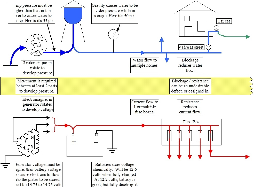
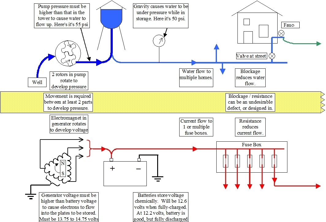
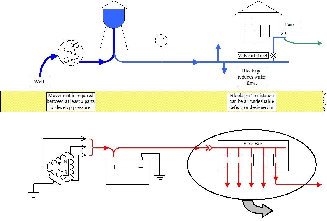
The reason for having you use a test light is all the voltage readings are only valid when current is trying to flow in that circuit. That means switches have to be turned on and fuses have to be in place. If it helps, everything electrical that you can't see can be compared to something with water that you can see or visualize. Think of your municipal water tower as the battery. It stores water under pressure from gravity. Batteries store electrical energy under pressure, chemically. The pipes are the wires and the valves are the switches. The only point of confusion is "open" and "closed" are exactly opposite. An open valve lets water flow, and an "open circuit", or "open in a circuit" is a break that stops current flow. A "closed circuit" is one that is turned on and there is a complete path for current to flow from the battery, through the wires, switches, connections, splices, loads, then back to the battery.

Water also needs a complete path, as in current flows down a river into the ocean where it evaporates, floats back up in a cloud that gets ripped on a church steeple, resulting in rain. It trickles back to puddles, storm drains, creeks, and back to the river. If you put a giant sheet of plastic over the ocean, evaporation stops, current flow stops, and you have an "incomplete circuit". No current flows anywhere.

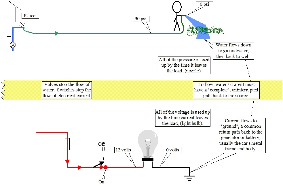
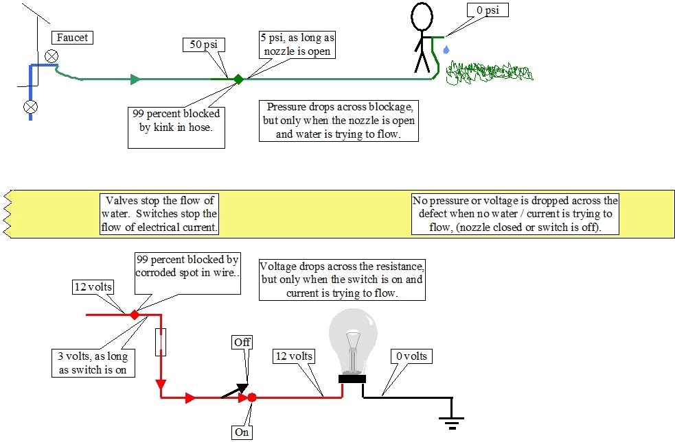
Now visualize a water pipe running to your house, then to an outdoor faucet. A garden hose is connected to the faucet, and a second hose is added to make it longer, then there's a nozzle at the end. With the nozzle closed and no water flowing, you'll have full system pressure everywhere up to that nozzle. Lets say that's 50 psi. If you were to stand on the hose and block it 99 percent, you'd still have 50 psi at the nozzle. That is the voltage you would read with a digital voltmeter and with a test light. In your truck, the typical scenario is you'd find 12 volts at both sides of every fuse, all the way up the various switches, and possibly a number of test points after the switches when they're turned on.

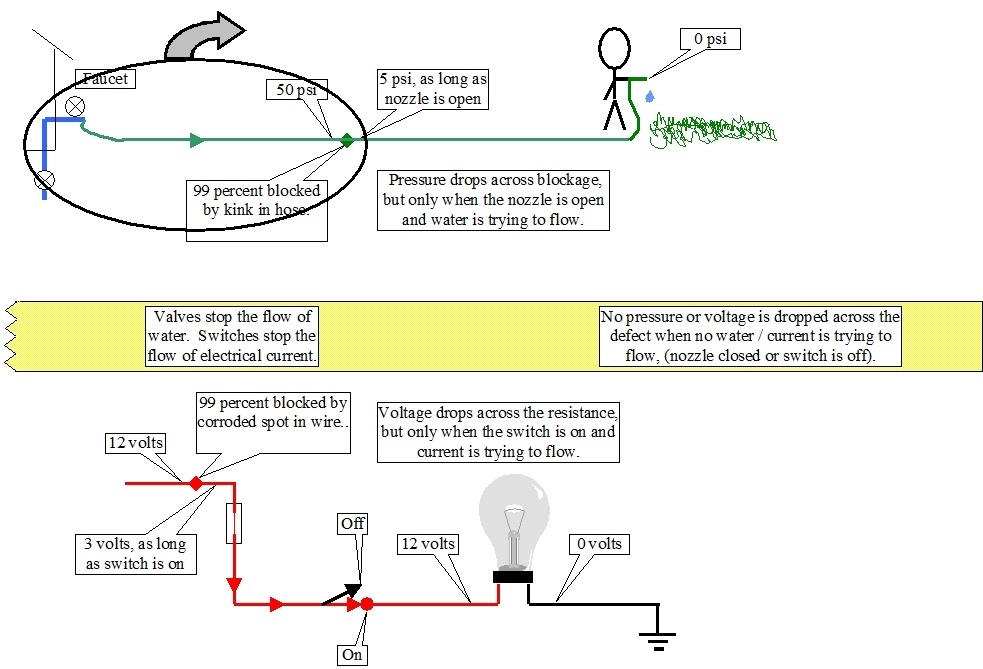
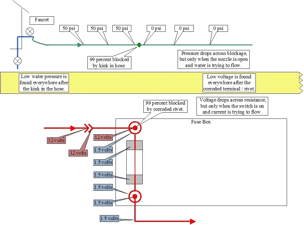
Now open the nozzle while you're still standing on the hose. With it 99 percent blocked, you can see not much water will flow out. Pressure at any point after your foot will be real low, as in almost 0 psi. Pressure before your foot will still be a nice strong 50 psi. In this sad story we already know where the restriction is. It's caused by your foot. What if you don't know where the restriction is located? It could be caused by the hose is kinked where it goes around a planter, the leg of a picnic table, or it just had a twist in it, then you tugged on it. The same pressures apply. If you don't mind poking a lot of holes in the hose, you could stick a pressure gauge in it at various places. Remember though, the nozzle has to be open so water is trying to flow. Then, if you find 50 psi at a test point, the blockage is after that point. Keep working your way down the hose until you come to a point where pressure is near 0 psi. The blockage is between that point and the last one where you found 50 psi. If the nozzle is turned off, you'll again have 50 psi before and after the blockage, so the test is useless.

Removing the fuse is equivalent to turning the faucet off, or closed. I have to stretch my story a little here. We know some water pressure will be stored in the hose. Forget that. Pretend that doesn't happen. With the faucet turned off, no water is trying to flow, and there will be 0 psi everywhere in the hose, before and after the blockage, whether the nozzle is open or closed, so pressure tests will be invalid.

Now lets get back to the electrical circuit. Amp meters, or "ammeters" measure current flow and they have to be placed in "series" in the circuit so current flows through them. This is similar to your water meter on your house. All of the water you use flows through that meter. Those have no place in this story. I only mentioned them to point out their difference. We're using a voltmeter which measures electrical pressure. As such, no current flows through the meter. If you live in the country and have your own well and water pump, there will be a pressure gauge on the storage tank. No water flows through that gauge. If it did, you'd have a wet floor. The same type of gauge is used on an air compressor. No air flows through that gauge.

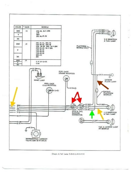
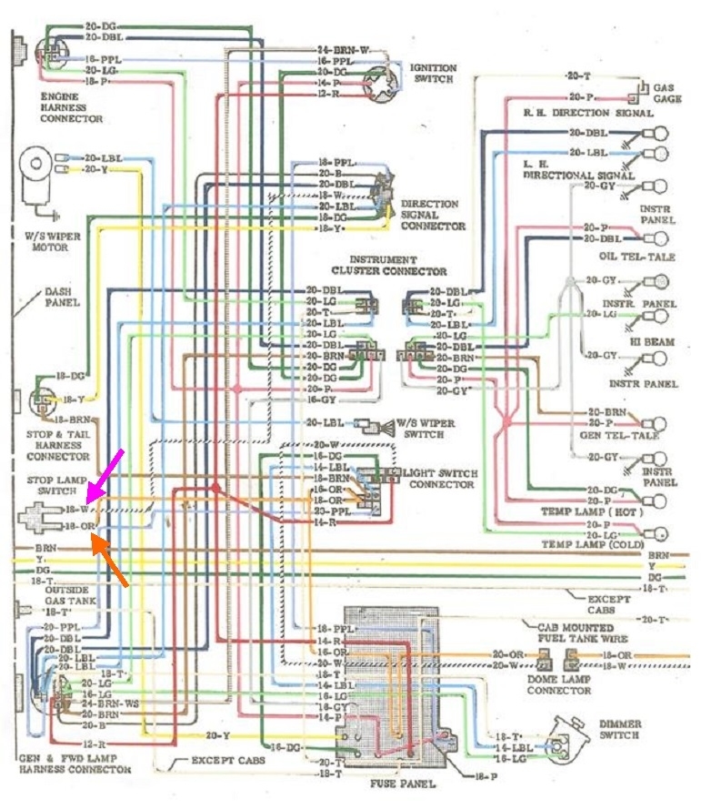
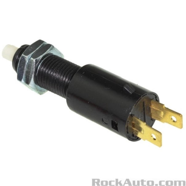
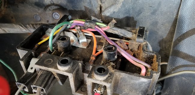
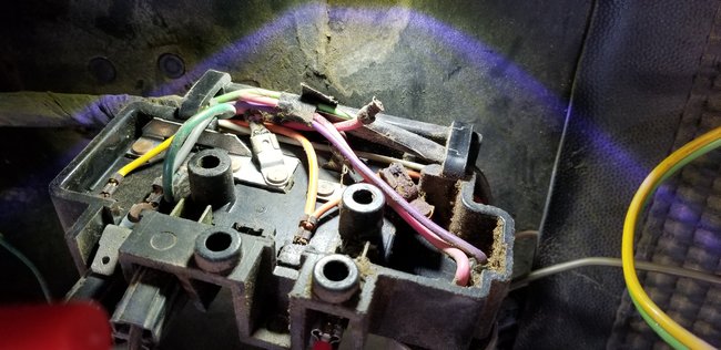
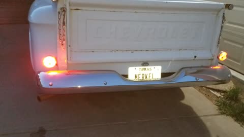
You have blockage in the circuit running to your brake lights. We know that because they don't light up when the brake light switch is turned on. As with the hose, we're going to find that blockage with pressure readings; in this case electrical pressure, or voltage readings. The faucet has to be turned on. The battery and fuse must be connected. The nozzle has to be open. The switch has to be turned on. Water must be trying to flow. Current must be trying to flow. Water pressure will be much lower after the blockage. Voltage will be much lower after the defect.

People who like working with their hands learn best by observing, and by manipulating things to see what happens. As such, we have a very hard time learning electrical theory because we can't see it. That's why so many mechanics run from electrical problems. Comparing everything to something corresponding with water, I never had a single student I couldn't get to understand basic electrical diagnosis. Simply understanding that people learn best in different ways takes a lot of the fear out of this subject.

To finish this story, the faucet is the fuse. The nozzle is the switch, and it's turned off. No water is trying to flow. There's still that blockage somewhere in between. If you were to connect a pressure gauge right at the nozzle, it will show 50 psi, so you'd incorrectly think everything is okay up to that point. That's what a voltmeter does. It will show 12 volts even though there's a spot of very high resistance somewhere that is preventing the circuit from working. The test light is different. Unlike the pressure gauge and the voltmeter, current does have to flow through it to make the light bulb glow. A bright test light indicates we have something close to 12 volts, and current is able to get through that far. This tells us the blockage is after that point. The voltmeter can't do that.

The only time the test light and the voltmeter will give the same correct readings is when there's a total break in the circuit. That break might equate to the second garden hose being disconnected from the first one. There would be 0 psi everywhere in the second hose. Same with a cut wire or a switch that's turned off. You'd find 0 volts everywhere after those points whether you used a voltmeter or a test light.

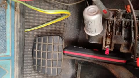
The reason I have you start with a test light is at first we don't know if you have a solid break or a high-resistance connection, as in a corroded splice or arced and pitted switch contacts. We aren't interested in the exact voltages a voltmeter will give us. A bright or dim test light is good enough, plus it puts a load on the circuit that causes current to want to flow. That is why they can be more accurate. Part of your description of the symptoms included finding different voltages at a point depending on what you did with some switches. That is exactly what points to a high-resistance point in the circuit. That is what we have to find and repair. Now you see why the test light works for that and the voltmeter doesn't.

To add one more chapter to this story, a lot of vehicles use "fuse link wires" instead of really large fuses. Those are simply a small section of smaller-diameter wire spliced into a larger wire. That makes it the weak link in the chain. It's a slow-acting fuse, and when the wire does melt, the insulation is designed to not burn or melt. A good one will act like a piece of wire when you tug gently on it. One that's burned open will act like a rubber band. The confusion they can cause is when they burn open, the arcing leaves a carbon track behind on the inside of the insulation, similar to what can develop inside a distributor cap. If a short occurs, the wiring is protected by that fuse link. No current can get through to run the circuit, but once the short is repaired, that carbon can still pass just enough current for a voltmeter to incorrectly say there's 12 volts there. I was involved with a very experienced transmission specialist who couldn't understand why he had 12 volts at the connector, but when he plugged in the brand new radiator fan, it wouldn't run. Simply switching to a test light showed he did not, in fact, have 12 volts there. The fuse link was burned open from the old fan motor which drew high current due to tight bearings. Replacing the fan motor was only half of the repair. It ran fine once the fuse link wire was replaced.
Mar 8, 2021 at 1:38 PM
Avatar
CARADIODOC
  • CERTIFIED EXPERT
  • 34,306 POSTS
All of the diagrams I've found so far have been very disappointing. Most are too blurry to read, and some don't lend themselves to understanding where current flows and what is connected to what. This is the best one I found so far. I'll explain how I figured some things out up to this point. If it's too hard to read, try copying it, then pasting it into an MS Word typing program. I selected "200%" to make it big enough to read.

We know the license lamp is tied in with the running lights. That's the brown wire, (brown arrow). It is spliced in at the left rear light socket. This will be the common 1157 socket with two contacts. The outer brass shell is the ground. They show it as a very tiny ground symbol at the bottom of the socket. Since we know the top contact is the tail lights, the bottom one has to be for the left turn signal and brake light. That's a yellow wire, (yellow arrows). If you follow that wire to the left, it comes to the two halves of a three-wire connector, (red arrows). From there it continues toward the cab, but I can't find that part of the diagram. Naturally that's the one we need.

The brown wire for the tail lights also goes through that connector. Then there's the third wire; a dark green one, (green arrow). That goes up to the right rear socket for the brake and signal light. They don't say where that connector is located, but if you can find it, that would be a good place to take some voltage readings. Remember, it has to remain connected so the circuit isn't broken. Probes can usually be poked in on the back side next to a wire to touch the terminal and take the reading.

For your particular truck, it doesn't pay to find that connector because we know the defect has to be well before it. You're having issues with the dash lights, and you've already figured out voltage is dropping at the fuse box when a switch is turned on. All of that comes before that connector, and before the rear lights.

Go back to the fuses with your test light. Find one where the test light turns on bright, then goes dim when you turn on a switch. With it dim, check the other side of that fuse, and I'm pretty sure you're going to find the same thing there. See how many fuses that applies to and see if you can read the labels under them.

What I didn't do a good job of explaining earlier is I'm hoping with your voltage readings I can figure out which comes first in the circuits. Most commonly a 12-volt wire comes through the bulkhead connector, then into the fuse box where it feeds multiple fuses. The other side of one fuse will go to the brake light switch. The second side of a different fuse will go to the head light switch. The disadvantage of doing it that way is if you have simply a shorted wire going to a rear tail light, that will blow the fuse, then everything including the head lights will be dead.

On newer models, while there is usually a very large fuse under the hood, just in case, the 12-volt wire still goes inside the cab, but it goes to the switches first, then each circuit coming out goes to its own fuse. Today you'll often see separate fuses for each head light, and others for the tail lights. This way regardless which circuit is shorted, only that fuse will blow, and all the other lights will still work. Overall it's more complicated, but the blown fuse tells you which circuit and which wire to follow to find the defect.

The last two photos show two different fuse boxes for your truck. Can you see the bulkhead connector and how to remove the fuse box? Voltage readings haven't verified this yet, but I have a suspicion that's the area we're going to find the defect.
Mar 8, 2021 at 2:26 PM
Avatar
CADEPHILLIPS
  • MEMBER
  • 19 POSTS
Well I had a long response typed out and now it's disappeared. If its allowed, I can always give you my phone number,and this will be so much quicker. Thank you for that long response it really does explain a lot. In my long ,somehow deleted response, I explained about taking my truck to my brothers so he could tried to help diagnose it also. He agrees that there is some kind of "load being drawn" when you pull the light switch. But we still can't determine where it starts. He thinks it is the switch but I agree that I need to take the fuse Box off to see behind it maybe that will shed more light. I will need to get a different test light because mine seems to have an LED light so it is always the same brightness. But I will work on getting you that information about the fuses.
Mar 8, 2021 at 5:53 PM
Avatar
CARADIODOC
  • CERTIFIED EXPERT
  • 34,306 POSTS
I used to have a computer that would lock up on occasion or I'd hit the wrong key and lose everything when it went to a different page. That was real frustrating after typing for a long time. It appears the site owners changed something some time ago, because now, if I just hit "page back", after a few seconds all my typing comes back. Even if I turn the entire page off, then go to my "History" page to reopen it, the typing is usually still there. So don't fret; I know what you're feeling. Sometimes pages fail to load due to a poor wireless connection, so I'm still in the habit of copying every reply just before I post it. That way, if it gets lost, I just click "paste", and it's right there again. Let me know if you don't know how to copy and paste. It's real easy to do. That could save you lots of aggravation in the future.

I get the feeling you're making this more complicated than it needs to be. Lets do it this way. Lets start with the brake lights. If you can identify the fuse for that circuit, pull it out, then check for voltage on both terminals in the fuse box. You're either going to find 0 volts on both, or 12 volts on only one of them.

If you find 12 volts on one fuse terminal, that tells us it comes in there first, then goes to the brake light switch

If I'm wrong, and you find 0 volts on both fuse terminals, check again while holding the brake pedal down. Now if you find 12 volts on one terminal, that tells us the 12 volts comes in to the switch first, then it goes to the fuse, and then to the lights. I don't think that's what you're going to find because that would leave more of the circuit unprotected by that fuse.

Assuming the first way is right and you do find 12 volts on one fuse box terminal, put the fuse back in, then measure the voltage on it with a digital voltmeter. You should see 12 volts. Now watch what happens to that voltage when you press the brake pedal. If the voltage drops real low, the defect has to be in the back of the fuse box, or in the wire coming through the bulkhead connector and feeding those fuses.
Mar 9, 2021 at 2:10 PM
Avatar
CADEPHILLIPS
  • MEMBER
  • 19 POSTS
So I'm finally to make a small bit of progress. Progress because I found a big problem but I realized that fixing it might not solve the entire problem because I believe there are now more issues that will come up. But the big story as you can see from the picture is that there is definitely a problem with that burned up connection. That supplied the bottom 2 fuses and I can only assume that when it was screwed to the fire wall there was enough pressure to keep a connection to light up my test light. And make my Volt meter read 12.7 but when I applied the brake my test meter went down to 5.4.
I will get that fixed and hopefully everything will work as it should. The other problem/issue that may arise might come from if I use the correct amp fuse as listed on the fuse block. I discovered that both those bottom fuses instead of being 15 amps each were 30 each.
So if I simply fix the wire issue it seems apparent that it could happen again at some time. If there were a short somewhere else in the line would that have caused it to burn at this week point? Meaning that if I replaced the fuses with 15 amps as it should be and I plug everything back in they would instantly blow if there was some other problem? I'm assuming you'll say it needs to be whatever the fuse block says however I'm starting to not trust where everything was wired. There just seems to be a lot of non stock-ness in the wiring, but what do I know. Does a 15 amp fuse sound correct for a brake lamp? I guess I always thought it would be more than that.that's sort of why I'm 2nd guessing it. what do you think? Hope all this make sense didn't have a chance to proofread it.
Mar 11, 2021 at 6:03 PM
Avatar
CARADIODOC
  • CERTIFIED EXPERT
  • 34,306 POSTS
These are excellent photos, but it's hard to tell some things when you're not looking at a live 3D object. I copied them into a typing program where I could blow them up, but even before that I see some suspect areas. You're right that wire nuts and crimp terminals are not original.

If you look at the first photo, I added arrows to the suspect areas. The red arrow is pointing to what looks like a wire that's corroded off the terminal. That looks like tape residue at the blue arrow. Be sure that isn't two wires that overheated and melted together. Lots of rust at the rivet by the purple arrow. Where a wire / terminal is connected to metal strips with two and three rivets, those have to be the 12-volt feed sides of those fuses. The "load" side, or wires leaving to go to their respective circuits, will always have just one fuse terminal for each wire, never two or more. That tells us the purple arrow is pointing to one of three fuses all fed from the same wire. The green arrow is pointing to just such a single wire, the yellow one. To say that a different way, if the fuse is blown, you'll still have 12 volts by the purple arrow, and the two-rivet strip to its left, but not on the yellow wire, as an example.

That terminal for the yellow wire is badly rusted too. That should be addressed even if it isn't the cause of the current problem.

Most people would simply repair or replace the rusty terminals, then look to see if everything works. I'd rather know exactly what is causing the problem, then solve it. There's three ways to do this. I want to be sure to confuse you unnecessarily, but each way might be the best choice at different times. The least-favorite way is to start at a dead light, (this is always with the circuit turned on and trying to work), with the test light, and you'll find you do not have 12 volts. Now move it back one step which might be at the three-wire connector we looked at a while ago. You find less than 12 volts there, so move back another step. Keep moving back toward the battery until you find the spot where you do have 12 volts. The defect has to be between those last two points. The disadvantage here is it could take you all day to finally get to the defect when it's near the battery.

My preferred method is to find a spot in the middle of the circuit and start there. If you have 12 volts, you just eliminated half of the circuit, and the defect has to be in the other half. Now take that second half and split it in half again. Check for 12 volts at that point. The voltage reading will tell you which way to continue the search. This is the fastest method because you will jump over the good parts and not waste time looking for convenient test points where there's no need to test.

The easiest method to describe is the third one. Start at the battery where you'll find 12 volts, then work your way along the circuit until you find the spot where the voltage is too low. You're just locating the defect from the opposite end of the circuit as you did in the first method. In this case, look at the second photo. I might be using the wrong feed wire for this problem, but it lent itself best to this explanation. Once again the circuit has to be turned on for the voltage readings to be valid. The 5.4 volts you found is proof there's a high-resistance connection, and we're going to find it now.

When you take the following readings, you have to be very specific where you place the meter's probe. Start at the red arrow with the probe on the terminal that's crimped to the wire. What'cha got for voltage? Now move the probe to the mating terminal, (blue arrow) and see what you have there. I should point out that you may need to poke hard enough to insure the probe is making good contact with the part you're testing at, but we want to be gentle enough that we don't inadvertently cause something to start working. If the bad connection starts working, there won't be a defect to find, then we'll give up and the problem will occur again days or weeks later.

Next, we can move the probe to the metal strip, (green arrow), or the rivet head, (purple arrow). GM likes to put convenient accessory terminals in their fuse boxes, and I suspect that is where that metal strip is bent up by the green arrow. I think you'll find the rivet is holding the fuse terminal to the metal strip, with the plastic fuse box in between. That rivet is an excellent place to find a bad connection. Typically you'll find a black ring arced around the rivet head, just barely noticeable. Often the way we see them is some minor sparking occurs there when the parts are moved a little or have pressure put on them.

If the green arrow is simply pointing to a tab that isn't used, the rivet head would be the next place to test. If you still have 12 volts up to this point, double-check on the other side of the box right on that fuse terminal. You found low voltage there earlier. That means you will have had to cross over the defect by this time. When you hit the first place with 5.4 volts, the defect is between that point and the one you tested right before it.

On the odd chance you do have12 volts all the way to both sides of the fuse, and the lights still aren't working, the high resistance has to be someplace after that. For the brake lights, the next place to check would be both wires at the brake light switch. If one has 12 volts coming in and the other has 5.4 volts going out, that switch has burned or arced contacts inside and the switch must be replaced. Yu can prove that by using a stretched-out paper clip or piece of wire to jump those two wires together to bypass the switch.

The next place in the circuit is the wire from the brake light switch goes out to the signal switch. Those can also develop burned contacts inside, but that usually only affects the lights on one side, not both sides. After the signal switch, the brake / signal lights are on two different circuits, so assuming we only have one defect, we know the problem can't be after that switch.

Before you get to the signal switch, for the sake of putting the truck together on the assembly line, there is going to be an electrical connector near the base of the steering column. It used to be common to see that connector black and / or melted around a pair of mating terminals. Those connectors are always open on the back sides so you can slide the probe in alongside the wires. Check the voltage on both sides of the connector. The wire you want is the same color as the one that left the brake light switch, usually white on GM vehicles, but you don't even have to know that. Just check each pair of terminals. If a pair has 0 volts on both sides, that circuit is turned off. If they have 12 volts on both sides, there's no defect there, regardless what circuit they're for. You're looking for a pair that has 12 volts on one side and 5.4 volts on the other side. If you do find the defect is in that connector, standard practice was to cut both wires off, splice and solder them together, then seal the splice with heat-shrink tubing. You'll only have to cut them apart again if you need to replace the steering column, or possibly the signal switch.

Related to those overheated terminals, or when that happens in a switch connector, the wires will be hardened for about four inches from that heat. Solder won't adhere to that, so you'll want to cut that four inches off each affected wire, then splice in a short length of the same diameter if necessary.
Mar 12, 2021 at 11:05 PM
Avatar
CARADIODOC
  • CERTIFIED EXPERT
  • 34,306 POSTS
To address your question on fuses, the common 1157 brake / signal light draws one amp, so there'd be two amps flowing through the fuse when the brake lights are on. Same for a left rear and left front signal light that are on at the same time. The smaller tail light filament draws around 3/4 amp. One in each corner, with no side marker lights, would draw close to a total of three amps, plus a little for the dash lights. Side marker lights, and the common 194 "peanut" bulbs used in instrument clusters and glove boxes draw close to a half amp each. A 15-amp fuse will be fine for those circuits, even if you connect a trailer.

If someone put in a larger fuse, it's still going to blow if there's a dead short in that circuit. The issue is what part of the circuit is going to be the weak link in the chain when too much current is flowing, but there's no dead short? Ever see one of the semi trucks with a gollyzillion orange lights all over it? The original circuit isn't going to handle that. Neither the fuse nor the wires can handle that much current, so that has to all be a custom setup, probably switched on and off with a relay. That would be an example of increasing the load on the circuit but there's no dead short. Suppose you had lots of additional lights on your truck, and in total they drew 25 amps. Obviously the 15-amp fuse would blow, but a 30-amp fuse would not. 14-gauge wire can handle 15 amps, and that is what is commonly used in cars and trucks for lighting circuits. That's why they get protected with a 15-amp fuse. If that circuit was asked to pass 25 amps, especially for a prolonged period of time, the wire would get hot enough to possibly melt the insulation. It would also tax the connector terminals and switch contacts. Those are also likely to overheat. Remember, that's if you added a lot of stuff to the circuit. If the circuit is left as designed originally, it will still work fine with a 30-amp fuse, and that fuse should blow to protect the wires from a dead short. What would be of concern is what if the wire has enough resistance in it that by itself would limit current to less than 30 amps? That would prevent the fuse from blowing and it would allow the wires to overheat. To put my mind at ease, I would want to put the 15-amp fuse in there if that's what was in there originally.

A better example of what can happen is when the bearings in the heater fan motor become tight. I can explain why if necessary, but for now, all we need to know is as a motor is loaded down, as tight bearings will do, it draws more and more current. We see that as the thermal fuse built into the speed control resistor assembly burns open, then the fan is dead. Many people replace the resistor assembly, then are confused and frustrated when it burns open again in a few days or weeks. The cause is that tight fan motor, but it is not shorted. Were it not for fuse devices of the appropriate current rating, that high current would stress the heater fan speed switch, and on most vehicles older than those from the late '90s, that current also passes through one section of the ignition switch. We used to see a lot of overheated connector terminals on ignition switches related to tight fan motors.

Most people will just tell you to put the right fuse in, but now you now why.
Mar 12, 2021 at 11:14 PM
Avatar
CADEPHILLIPS
  • MEMBER
  • 19 POSTS
Hopefully it will not take too long to get that wire and connector replaced. It had not even dawned on me that that was corrosion, I thought that it was the short, and that is why it was burned and broken in two. I will also try to get the rest of the back of that fuse block cleaned up and remove the spider nests. Who knows that might reveal something else. I'm also going to need to brush up on where these relays/switches are that I will need to check. But I guess before I do any of that I will get that wire fixed and replace the two 30 fuses with the correct 15 amps. Then I'll be able to start on checking all those spots you labeled with the colored arrows. With time change coming up tonight I should be able to have more daylight to work on it anyway and maybe take some better pictures that may help.
Mar 13, 2021 at 3:30 PM
Avatar
CARADIODOC
  • CERTIFIED EXPERT
  • 34,306 POSTS
I wouldn't do any repairs yet, or even replace the fuses yet. There's a dozen good places to find the defect, and one of them could even be where the 12-volt-feed fuse box terminal has the fuse snapped into it. Continuing on with my previous procedure, you would touch the meter's or test light's probe to the fuse box terminal, then to the end of the fuse plugged into it. Those two points are shown with the arrows in the first photo. If you find 12 volts on the fuse box terminal, (blue arrow), but 5.4 volts on the fuse, (green arrow), that connection has to be where the high resistance is. Look at the rust on the terminal just above the green arrow. That is a dandy place to suspect a high-resistance connection.

If you were to pop the correct fuse in first without doing any testing, the scratching action is going to scrape off enough of any light film of corrosion that the high resistance is gone. The circuit will work now and you'll never know why it didn't work before, and you'll always be worried it's going to act up again.

Electrical specialists including myself often complain about Chrysler's wiring diagrams that bounce around between multiple pages in the service manual, and each page has just a tiny portion of the circuit on it. Even back in the '90s, there could be over 100 pages of diagrams to cover just one or two car models. But here is the exact opposite. The entire electrical system for a '72 Dodge Challenger fits neatly onto two pages and is easy to follow. GM's engineers thought it would be easier to put everything on one page, and here's what they ended up with in the second diagram. It is completely impossible to know where each circuit runs because they don't show which switch wires are connected when turned on, or which terminals in the fuse box have a fuse between them. This is just too impossible to follow, however, coupled with my wondrous memory, we can still figure out where to go.

My memory of wire colors in the '70s still holds true for a '66 model. The brake light switch is shown at the far left of this diagram, and the orange wire is the 12-volt feed. If you follow that wire to the right and down, you'll see it comes from the fuse box, but I also noticed it runs to the head light switch first. That tells me that circuit feeds something more than just the brake lights. That has to be the tail lights and / or the head lights. If we knew which other lights that feeds, and if those lights work correctly, we would know everything, including everything inside the fuse box has to be okay. On the other hand, if the brake lights are dead, and the circuit at the head light switch is also dead, we would know the defect has to be before the head light switch.

As a side note, if that orange wire at the head light switch is feeding the head lights along with the brake lights, a 15-amp fuse is not big enough for that circuit. One high-beam head light draws close to six amps. Two would draw a total of 12 amps. There needs to be some safety margin built in to prevent nuisance blown fuses. They normally don't want to exceed 80 percent of a fuse's rating under normal circuit operation. Add in any tail lights that might be on that same fuse, plus the intermittent brake or signal lights, and even a 20-amp might be too small. Once we get this solved, we can worry about figuring out which are the correct fuse sizes.

The first step is to measure the voltages in the fuse box, but I'm going to jump ahead since you asked about the switches. The third photo shows what your brake light switch looks like. The arm of the brake pedal presses on the white button at the top left to turn the switch off when that pedal is released. Either terminal can have the orange wire plugged into it, then the white wire will plug into the other terminal. The switch mounts to a metal bracket that may be attached to the steering column or to the frame of the dash board. The terminals will be open and exposed on the back where the wires go in. Those are easy places to take voltage readings.

The white wire runs to the signal switch. It sits right under the steering wheel, but testing it gets to be real easy. The fourth and fifth photos show two views of this switch. The switch contacts are on two halves that are riveted together and are non-repairable. One half is stationary and mounts to the steering column. The other half rotates, or slides over the stationary half to make different connections for the turn signals. As such, the turn signal lever is bolted to that movable half. You can see in the fifth photo the wires run into the assembly, and there's no place to take voltage readings. You have it much easier. The fourth photo shows the two connectors, and you'll see that long wire harness they're attached to. Those run through the steering column and come out under the dash board.

The sixth photo shows one of those connectors, and the seventh one shows one connector turned just enough that we can see where the wires run in to the terminals. That's where you can poke the probe to take the voltage readings.

When you apply the brakes, the brake light switch switches on the 12 volts that goes to the signal switch. With the signal switch released, current flows through it and out on two different circuits, one for the left brake light and one for the right brake light. If the defect is before the signal switch, both brake lights will be dead.

What many people forget or overlook is the brake light switch only supplies the 12volts for the brake light function. You still need 12 volts to the signal switch for the turn signals when the brake light switch is off. That means there has to be a second 12-volt source to the signal switch. That one comes through the flasher and it is likely to be on its own fuse. We know that because the brake light circuit can operate any time, but the ignition switch has to be turned on for the signals to work. The point of this part of the story is the two rear circuits might work properly when the signal switch is turned on, but not when the brake light switch is turned on. There is value in knowing that. If the signals work in the rear, that is proof those bulbs, and the wiring all the way back to the signal switch, including at least part of the signal switch and some of the connector terminals have to be okay, and there's no need to do any testing in those areas.
Mar 13, 2021 at 5:09 PM
Avatar
CADEPHILLIPS
  • MEMBER
  • 19 POSTS
That last part of your response is spot on and I will explain that hopefully in a bit. But 1st I think I may have not communicated well about the 5.4 V, So it may take a couple replies from me to get my point across I hope. The only time there was 5.4 volts was only in the bottom 2 fuses and only when I applied or pushed on the brake pedal. It was on both sides of the fuses and on both the terminal and the actual fuse. All the other fuses acted normally even if they didn't work. So I tested each spot on the bottom two fuses and terminals before I ever removed the fuse block. Each spot made the test light light up and read 12.7 on my Volt meter. Then as I pushed on the brake pedal it instantly went to 5.4 in each of those spots every time I did it on the bottom two only.
After I remove the fuse block obviously neither one of the bottom 2 slots have any voltage at all because of the broken wire in the picture I sent. Like you said it looks corroded I'm going to send a few better pictures I don't know maybe that is heat because it looks like 1 of those wires closest to that connection got a little melted or at least warm. So anyway none of those bottom spots can be tested since there is no longer a wire connected to them that's why I thought I needed to fix that connection, to continue testing. And here is the interesting thing if I put my voltmeter on the end of the wire that is now broken it measures 12.7 when I push on the brake it still measures 12.7 , no change. Which if I'm thinking correctly would mean that when it was hooked up, the problem would have been further down-the-line somewhere. I will end this part with hopefully some better pictures showing the broken wire. Then I'll start again with some new information.
Mar 14, 2021 at 5:14 PM
Avatar
CADEPHILLIPS
  • MEMBER
  • 19 POSTS
Okay, so something I have not mentioned that I did not think was relevant until that last point you made about the brake lights and signal lights. It takes a little explanation but here goes. I have Sylvania red LED bulbs plugged into those tail lights in the video I will send. In the video I have the brakes pushed in with a log and the signal light going at the same time. You can see that the signal light and brake light appear to work at the same time. however what looks to be the brake light is not near as bright as it would normally be. So I'm guessing that that dim light is caused by the 5.4 V. I plugged in some conventional light bulbs to see if it would do the same thing and no dice. Only the signal light would work.
So as you said there should not be any issue from the tail lights backup to the fuse block. Since it seems the signal light works and the brakes light works if it had the correct power. So that means the bad connection is somewhere else. Or could it mean that the broken connection could have been the problem? But if that was the case how could only 5.4 V get to the back? I figured if the connection was broken nothing would get to the back. Perhaps the broken connection was penned together or mashed together behind the fuse block and that is what only allowed 5.4 to get to the backlights. I sound like I'm grasping at straws now.
I don't have any pictures of this but if I remember correctly when I pulled the headlight switch the headlights do come on but with the LED lights in the back only one would light up. Which again makes me think it was only getting enough power to light up a single bulb.
Mar 14, 2021 at 5:38 PM
Avatar
CARADIODOC
  • CERTIFIED EXPERT
  • 34,306 POSTS
You were right all the way down to the last few sentences, then the thought train got derailed. I know exactly what you meant earlier with the 5.4 volts, and that is the proof there was a high-resistance point in the circuit, but it had to be before that point where you were measuring.

Now you found a constant 12 volts on the end of that broken wire, which still agrees with my assessment. You no longer have a circuit that's turned on, so there can't be any current flow. Remember the garden hose that you're standing on? As long as it's no more than 99 percent blocked, and the nozzle is closed, you'll still have full voltage, ahh, I mean pressure, up to that nozzle.

By that wire breaking off, that is the equivalent of you blocking the garden hose 100 percent, so no pressure can get through. Now you're taking a pressure reading right next to your foot, on the faucet side, and finding full pressure, or in this case, 12 volts.

Based on your observation of what looks like an overheated wire, what likely happened is it started to corrode next to its terminal. All you need is one tiny strand still intact to find 12 volts on the fuse, . . . as long as no current is trying to flow through it, meaning the circuit is turned off. Once you try to make the circuit work, there's no way enough current can flow through that one or two strands, just like there's no way you can get much water out of the garden hose when the nozzle is open and you're standing on the hose.

Assuming I'm right, that wire has to be shined up, and you'll need to find a rust-free point anywhere on that metal strip, then solder the wire to that strip, and the circuits will work. If I'm wrong, there is still a high-resistance point that we have to find, and that wire may have just been brittle enough to break off once you moved the fuse box. The way I would approach this is to scratch a shiny spot on the metal strip, then lay down some solder first. Now put some solder on the end of the wire so it flows through all the strands. The last step is to hold the wire on the metal strip, then heat it until the solder melts into that on the strip. Check out this video too:

https://youtu.be/4TjSYfLTHfg

After rereading your last comment about the defect being further down the line, technically you're right, but with the garden hose, you took a pressure reading right next to your foot, as in an inch away, then you would be correct; the defect is further down the line, (an inch away, in this case). With the broken wire, the point of high resistance is further down the line from the end of that wire, as in 1/16" further away, right where that wire was connected. To say that a better way, you have half of the defect in your hand. The other half is where that wire was connected.
Mar 14, 2021 at 5:59 PM
Avatar
CARADIODOC
  • CERTIFIED EXPERT
  • 34,306 POSTS
I posted my last reply while you were adding your last one, so we're a little out of sync.

You're starting to over-think this. We started with 50 psi at the faucet, your foot is blocking the hose 99 percent, and we still have 50 psi at the nozzle as long as it's closed. Same with the full 12 volts at the fuses..

Now you open the nozzle, and since the hose is one percent open, there is some current flow, but pressure drops to 5.4 psi after your foot, but only as long as water is trying to flow. You have 12 volts of pressure at every place after the defect, until current is trying to flow, then it drops to 5.4 volts everywhere after the defect. That's why you originally found 12 volts on the fuses until you turned on a switch, then it dropped to 5.4 volts.

You only will have 5.4 volts after the defect, and you'll still have 12 volts before the defect. All those test points I added arrows to were just to find where there was 12 volts and where there was 5.4 volts. That's how we locate the defect.

As for your LED lights, I sell a lot of them at the nation's second-largest old car show every year. A single LED turns on with as little as 1.2 to 1.6 volts. They typically put three in series so in total they need roughly five volts, then they add a "dropping" resistor to use up the additional 7 volts from the 12-volt system. Next, there's multiple groups of three like that which are connected in parallel, so they all get 12 volts, but some current flows through one group, and different current flows through each other group. This would equate to having two faucets on the outside of your house, each with its own hose. Current that flows through one hose doesn't flow through the other hose, but both faucets supply 50 psi..

The other important fact about LEDS is unlike an incandescent bulb that can be dimmed, an LED is only fully-on or fully-off. For all practical purposes, there is no in between and no dimming possible. More on this in a moment.

There's usually more circuitry inside a 12-volt LED bulb. Because of the fact they turn on at such a low voltage is why you see them start to work with only 5.4 volts. That extra circuitry kicks in and limits current flow before the voltage gets up to 12 volts. If you use an adjustable power supply, you would see you can run these up to at least 18 volts with no change in brightness. Basically all this means is you added another variable that complicated the issue.

To address the dimming issue, little 194 replacement LED bulbs will not work in your instrument cluster because those original lights are dimmed with a rheostat. That is simply a variable resistor. The more resistance you dial in, the more it restricts, or reduces, current flow. With less current, incandescent bulbs glow less brightly. If you put LED bulbs in there, they will be either full brightness or totally off, as you rotate the rheostat, with just a tiny sweet spot where they might flicker or dim a little. You need to use an electronic dimmer, similar to what is used in a house. LEDs are dimmed through "pulse-width modulation", which is identical to how fuel injectors are pulsed on and off. With the lights, the 12 volts is switched fully-on, then fully-off, typically around 400 times per second. They add a chemical to the lenses to give them some "persistence", same as they used to do with picture tubes. That retains the glow for just an instant so we don't see that pulsing as flickering.

If you pulse the 12 volts on ten percent of the time, then off 90 percent of the time, the LEDS will appear to be dim. If you pulse them on 80 percent and off 20 percent, our eyes will see that as fairly bright.

As far back as at least the '93 Dodge Intrepid, they used an electronic circuit to dim the dash lights in this same way, and they may have used LED lights at the same time. That type of dimmer will work with incandescent bulbs too, but first of all it isn't necessary, and second, those bulbs draw a lot more current, so the switching transistor has to be tough enough to handle that higher load. There's no advantage to switching over to this type of dimmer if it isn't needed. Heat, moisture, and vibration are the three biggest enemies of delicate electronic circuits, so by all means, lets plant as much of that unnecessary stuff in our cars. The old-style rheostat was nothing more than a long piece of wire coiled up in a ceramic housing. The wire was made of a material that had more resistance in it than copper, aluminum, or steel has. Failures of those are possible, but extremely uncommon.
Mar 14, 2021 at 6:41 PM
Avatar
CADEPHILLIPS
  • MEMBER
  • 19 POSTS
I'm going to go back through all this discussion and making a list of everything I'm supposed to test. So far everything I have tested has been the same as originally mentioned.
The bottom 2 fuses test over 12 until you push on the brake and then they go to roughly 5.4. I was able to test what I believe to be the brake switch and it does the exact same thing shows 12 until you push the brake then goes to 5.4.
The upper fuses the top fuse and 3rd from the top only work when the key is turned on and they show 12 all the time after that. the 2nd slot however has yet to work at all while I've been testing.
So what else do I need to test? I know I'm leaving something out somewhere and I keep thinking it must be the headlight switch because if in fact the brake wire does go through that switch somehow, then to me that says a lot because everything that does not work correctly somehow is wired through that switch in some way shape or form. Brake light, tail light, interior light including panel lights. So if that's true how do I go about checking the switch and all the wires poking out of it?
Mar 15, 2021 at 7:33 PM
Avatar
CADEPHILLIPS
  • MEMBER
  • 19 POSTS
I will check again those bottom fuses and terminals separately when I get off work today. I guess I've been so focused on trying to find 5.4 I keep forgetting that those bottom 2 slots go to nothing when ever you pull the headlight switch. I'll check again today like I said. I am also now not hearing my electric fuel pump anymore when the key turns on so I'll need to see if it is burnt up or if some other wire as loose. Which means now I get to remove the bench seat out of the cab , but at least that will give me some room. And then it's only a matter of time until the wife puts the foot down and we drag it to a mechanic.
Well anyway if you do think that I can check the headlight switch ,any idea on how to check it? Or more to the point how to remove it . I cannot find a set screw anywhere to remove that knob so that it will come off of the dash. I feel like I could pull on a hard enough to probably forcibly remove it, but I am sure that is not the way it should be done.
Mar 16, 2021 at 4:09 AM
Avatar
CADEPHILLIPS
  • MEMBER
  • 19 POSTS
Just wanted to try to add this video that shows what I wrote about that you go to almost 0 in milli volts when I pull the headlight switch for the parking brake and when I pull at 1 further for the headlights then it goes negative. I also show what happens when I apply the brake. And when you pull the headlight switch it overrode the 5.4 on the brake and drops it to nothing. So no matter what the headlight switch kills the bottom 2 slots that were fed by that broken wire. not sure of this will be helpful, but who knows.
Mar 16, 2021 at 4:43 PM
Avatar
CARADIODOC
  • CERTIFIED EXPERT
  • 34,306 POSTS
You're getting hopelessly wrapped around the axle. Forget the head light switch and the brake light switch. The defect is in the fuse box.

You're standing on the garden hose, but you're insisting on looking for the problem after the nozzle.

For the head light switch, you have to reach up on top of it to press a little spring-loaded button, then you pull the shaft out with the knob. There's a nut to unscrew where the shaft went in, to remove that switch.
Mar 16, 2021 at 7:13 PM
Avatar
CADEPHILLIPS
  • MEMBER
  • 19 POSTS
I guess what I do not understand is why I have not yet found the defect if all I have been testing is the fuse Box. Every post ,terminal, and fuse going in and coming out. So I still need to check for incoming 12 V and out going 5.4 V or at least low without having pushed on the brake pedal or pulled the head light switch or anything, just the fuse box alone. If there is anything else I need to search for please let me know, anything will be helpful at this point I'm really no further along except to know that there is still a problem and now I have a broken wire at the back of the fuse Box. I have it rigged together so that I can still get readings. I have never soldered before so I don't own any of that equipment. I'll probably have to get son in law to show me.
Mar 17, 2021 at 2:15 PM
Avatar
CARADIODOC
  • CERTIFIED EXPERT
  • 34,306 POSTS
Did you watch the video on soldering? Here's the link again so you don't have to search for it:

https://youtu.be/4TjSYfLTHfg

This video covers every possible step for the benefit of people who have never done it before, but in actual practice, it goes a lot faster. In one step he pointed out putting a little solder on the tip of the iron while the tip was on the wires. What wasn't clear is that solder was only to promote better heat transfer into the wires to make them hot enough to melt more solder.

Once the wires are hot enough, the next step is to touch the roll of solder to the other side of the wires. When it melts, molten solder is drawn toward the heat source, meaning the tip of the soldering iron. That is the only way to get solder to flow through all the strands. Once that flow is achieved, there's no value in dumping more solder onto the joint. Pull the iron away, and be careful to not move or wiggle the wires until the solder hardens. That will take just a few seconds, and you'll see it turn from shiny silver to a slightly dull gray.

That's for soldering two or more wires together. Your repair is different, and a different technique works well. As with all soldering jobs, the parts being joined must be clean and shiny. Solder will not adhere to rusty or corroded wires, or those that were previously overheated, such as at overheated switch connector terminals. Overheated wires will feel hard to bend and won't be as flexible as the rest of the wire. That usually means cutting off four inches of old wire and splicing in a new section if needed. That's a story for a different day.

You have a wire that broke off, and it was attached to a terminal that is riveted to one of those silver buss bars that are attached to the fuse holder clips. It is not practical to try to drill out the rivet to remove that terminal, then solder a new terminal to the wire and rivet it back on. It was done that way on the assembly line because that was the easiest way at that time. For the repair, we're going to attach that wire with solder instead of a rivet. The silver buss bar has to have a shiny spot anywhere on it that is convenient to reach the wire to. Next, when you strip the insulation off the wire, that copper has to be shiny too. Since enough moisture got up there to corrode the wire off the terminal, it is likely that corrosion wicked up the wire a little way too. You'll see that as a reddish rust-colored wire. It is usually too difficult to shine up each strand with sandpaper. Instead, keep cutting the wire and insulation back until you reach shiny copper.

Start by adding solder to the wire, but again touch it to the opposite side as where the tip is so the solder will flow through the strands toward the iron. It's okay to put enough solder on to leave a blob on the end. Now flow some solder onto the bar in the fuse box. This can be a little tricky and frustrating. It will work better if you have a large soldering gun. Weller made the most common one years ago. We used to use them in tv repair, but they're way too big for delicate electronics work today. The problem with the little soldering irons is their heating area is too small. The silver bar in the fuse box will suck the heat out of the iron's tip and lower its temperature too low to melt solder. If you hold the tip there long enough, the temperature will finally come up high enough, but by that time you'll start to melt the black plastic of the fuse box. In the worst case, that could melt around the fuse terminal clips causing them to be loose or to pull out. A larger soldering gun provides much more heat so you can get in, flow the solder, and get out fast enough for the parts to cool down before any plastic melts.

The point of putting solder on the bar first is it takes some time to build the heat and to flow the solder. If you try to heat the bar through the wire, it will take much longer and will usually result in a "cold" solder joint. That is one that does hold the pieces together, but the solder is left more crystalline and makes for an easy joint to crack apart. Once you have a nice pad of solder on the bar, in the next step you don't have to heat up that entire bar. You only have to heat the solder to its melting point. With its blob of solder on the end, place the wire on the solder on the bar, then press the tip of the iron on the wire. When the solder melts, gently press the wire into the solder on the bar and let them melt together. Remove the iron as soon as that happens, but you'll have to hold the wire for a few seconds. Careful; it can get hot. Just like you need shielding gas with a wire-feed welder, you need flux with solder to make it flow better. If you hold the iron on the molten solder too long, that flux burns away, leaving a weaker joint. The hardened solder should be smooth and shiny when you're done.

You must use rosin-core solder for any electrical work. Older acid-core solder used for plumbing and radiator repairs uses acid for the flux. That has to be cleaned off those repairs because that acid will eat into the joint over time, causing the joint to crack apart.

Once that wire is attached, we can continue with the diagnosis. I understand your confusion in the fuse box. I have a strong suspicion everything is going to work properly once you have that wire attached, but also, I'm working on a drawing that I hope will help explain better what I'm trying to have you do. If you look back at the photo I posted of the rear of the fuse box, with the four arrows, I think this will make more sense.
Mar 17, 2021 at 4:53 PM
Avatar
CADEPHILLIPS
  • MEMBER
  • 19 POSTS
Where would be the best place to find a good soldering gun and your recommended solder since Radio Shack is no more? But first I'm going to need to strip that wire and see if I can find any slack in it. It doesn't appear to be very long. I'll need to trace it back and see if I can find any slack or maybe just add a little extra wire.

Just as a side note I'm sure this would be enjoyable sitting at a desk rather than under a cramped small dark space for a person that is not small himself. I'm sure I'm going to need to use a brace or something to hold the fuse box still when I attempt all this anyway. I really did not want to take out that bench seat but I may have to just to get room.
Mar 18, 2021 at 4:56 AM
Avatar
CARADIODOC
  • CERTIFIED EXPERT
  • 34,306 POSTS
Sometimes the seat can work in our favor by giving you something to prop yourself against.

You may be able to use stretched-out bungee straps to hold the fuse box from moving around. Dropping solder onto the metal strip and onto the wire isn't too difficult. It's when you heat the two together that it's important to hold them steady for a few seconds until the solder hardens Normally we want to have a solid mechanical connection first, then a strong electrical connection. That means twisting the wire around something so it is held tightly in place. That's the mechanical connection. The electrical connection is not supposed to be relied on to physically hold things together, but that will work just fine in your fuse box. I find the wire gets too hot to hold onto for those few seconds I have to hold them, so I look for away to hold it in place some other way. Often that can be done with alligator clips or clothes pins. Even a paper clip can be used to hold one wire to another one that acts as an anchor while you do the soldering.

In the 1970s, the most popular soldering gun for repairing tvs was the Weller model 8200.. You can still find them on eBay. We got disgruntled when the cost of replacement tips shot up to over $3.00 for a pack of two, so we switched to using smaller soldering pencils. We had to do that anyway because that was about the time printed circuit boards were becoming more common. I think the 8200 is still a current model in a lot of hardware stores.

One of the things that used to be the hardest on the tips was accidentally or intentionally melting plastic with them. Acids in the plastic attack the copper and cause it to burn away faster. This is not a concern if you use the gun a few times per year. We were using them dozens of times per day back then.

You can find very inexpensive pencil soldering irons in hardware stores and places like Harbor Freight Tools. They work fine for wires, but will probably have a hard time heating up something as big as that metal strip. You can also find these as part of a "soldering station". Those include a temperature adjustment.

The better tips are coated in tin to make them last longer. I bought six soldering stations in the md '80s, and the one I use most often still has the original tip in it. You still have to clean and tin them as shown in the video, but they're less likely to burn away over time if you bump them into something plastic.
Mar 18, 2021 at 7:17 PM
Avatar
CARADIODOC
  • CERTIFIED EXPERT
  • 34,306 POSTS
Okay, start with these and see if they make sense. I worked on these all night. This is something I've wanted to do for a long time.

It would appear I have a lot more work to do. I can't figure out why some text boxes don't transfer. The top left one is supposed to say,

"Pump pressure must be higher than that in the tower to cause water to flow up. Here's it's 55 psi",

and the one right below it should say, "Well".
Mar 18, 2021 at 8:08 PM
Avatar
CARADIODOC
  • CERTIFIED EXPERT
  • 34,306 POSTS
Try these. I'm going to double-check the rest of the drawings before I post them.
Mar 18, 2021 at 8:54 PM
Avatar
CARADIODOC
  • CERTIFIED EXPERT
  • 34,306 POSTS
Step 1. The defects are pointed out on the second half of the circuits.
Mar 18, 2021 at 9:24 PM
Avatar
CARADIODOC
  • CERTIFIED EXPERT
  • 34,306 POSTS
Step 2. The areas circled will be expanded next. Those are the areas with the defects. I'm posting these separately to reduce confusion.
Mar 18, 2021 at 9:26 PM
Avatar
CARADIODOC
  • CERTIFIED EXPERT
  • 34,306 POSTS
Step 3. The lower half is what could happen in your fuse box. In this example, the rivet where a wire is attached is corroded and there's a very high-resistance connection there. With the hose, you'll have full pressure up to the kink. With the electrical circuit, you'll have full 12 volts up to the bad spot. The callouts show all the places you could take a voltage reading. The red ones show 12 volts before the bad spot, and the blue ones show low voltage after the defect. The various electrical switches aren't part of this story. They come much further down the line, well after the defect, just like the nozzle is much further down from the kink.
Mar 18, 2021 at 9:34 PM
Avatar
CADEPHILLIPS
  • MEMBER
  • 19 POSTS
Well, good news. I was able to clean up that corroded broken wire which did make it very short but still able fit a wire and connector on it and then connect it back to that bar. I did try to squeeze my frame under there to solder but I don't think Tyrion Lannister could have fit, pardon my got reference.
Well, now everything works again. Brake lights, tail lights and dash lights, all is well with the truck.
Mar 22, 2021 at 4:27 PM