Update.....
First, clarification about the 75 and 85 degrees... That wasn't outside temp, that was what I was hoping the system might be able to provide inside.... :-) Outside was a balmy 55. (Eat your heart out..!!) From the sound of it, you might be living in the Dakotas or up in those latitudes.... Too cold for a SoCal boy.....!!!
I was thinking along the same lines you were.... And, I'm thinking I might have to start keeping a logbook of what's going on at the time, lights, wipers, A/C, etc....
Today, it reverted back to its old ways with the temp and fan speed erratic and unpredictable... had to go back to manual operation....
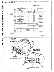
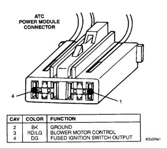
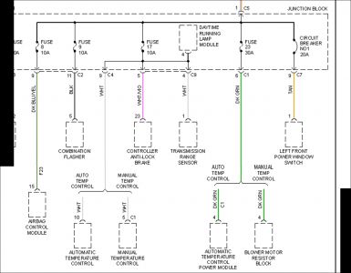
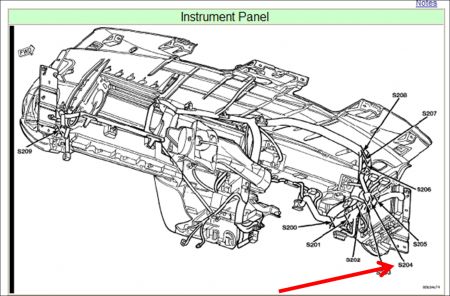
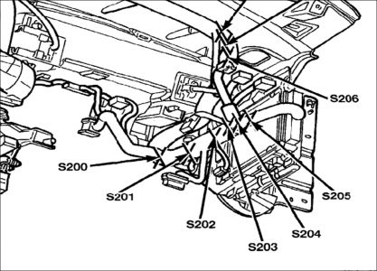
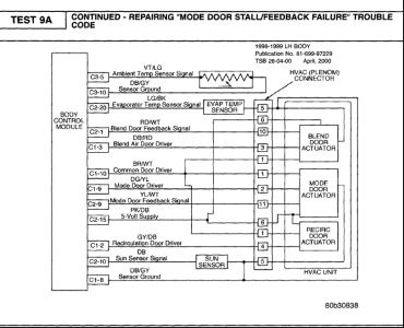
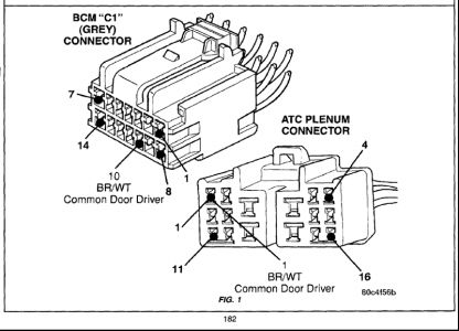
Your suggestion about the ground wire is a good one. And, looking at the BCM and A/C schematics, I see there are several types of grounds that these systems use: BCM-chassis grounds (BCM 20-pin connector, pins 1 and 20) and BCM sensor grounds (BCM C-1 pin 8 and BCM C-3 pin 10). When I can dedicate some time with the ohmmeter, I'll chases each of these and then see if I can't solder in temporary jumpers to ground for the chassis ground connections. For the sensor grounds, they really aren't a "ground" in the sense that they are "common" with the chassis grounds. They are technically signal returns for those circuits. Putting that to chassis ground could adversely affect the systems' operation or damage the BCM. What is interesting about the sensor ground issue is that the A/C system is acting as though the temps are going all over the place and it's chasing them with temp and fan speed variations. This could also be due to an intermittent ground for the system which your suggested jumper might reveal.
One thing that also is happening with the A/C system is that the temp display occasionally goes blank. It may come back in a few minutes or it may not for a longer time. I don't see that as a PCI bus communication failure because I can still control the A/C system manually which would be impossible if the PCI bus were open or shorted to ground.
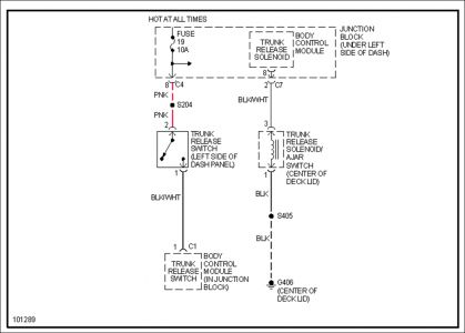
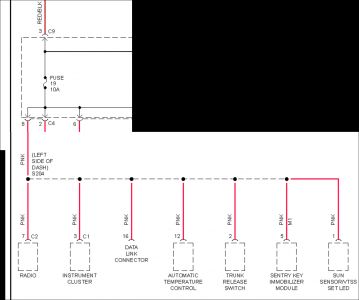
As far as using a jumper for the hot side, I can pull the fuses individually for the BCM (fuse #s 14 and 19) to see what the system reaction is. I'm guessing that fuse # 19 is essential for system operation and will kill everything if it goes away. That would tell me that a jumper wouldn't be necessary. On the other hand, if pulling fuse doesn't give an immediate, obvious reaction, then using the jumper would be the next step. I'll also go through the same process for the ignition switch controlled fuse, # 14. That one, I suspect is just a "signal" input to tell the system that the system can operate because the ignition is in either run or start.
I really need to find out if there is a schematic for the Junction Block. There's a lot going on inside and going through that beast. Without a schematic, I'm assuming that the only info I need to know is what the other schematics tell me. I'm not built that way. I want to be able to wring out the continuity of all the circuits in it to eliminate it as a suspect.
What I'd really like to have is a full up test bench where I can run a complete systems simulation and verify the correct operation of all components. I've actually considered creating a breakout harness and installing it between the BCM and the Junction Block so I can monitor voltages while it's in operation..... It really wouldn't be too hard; there are only 20 pins involved......
Didn't look for a mfr name on the BCMs. I'll do that when I get home tonight.
Last thought, then I'll sign off for now. Do you know if Chrysler has a technical services office we can tap into that might be able to supply me with more in-depth info regarding the operation of the BCM and things like the schematics for the Junction Block...???? You can see that I'm really on a mission now......
Have you seen any of my Personal Messages...???
Back to work..... Talk later, Sir.... Stay warm....
BG
Dec 16, 2008 at 3:21 PM