Alternator burned now problems ensue?

2011 JEEP GRAND CHEROKEE LAREDO
120,000 MILES • 5.7L • V8 • 4WD • AUTOMATIC
Avatar
LEPRIKAAN
  • MEMBER
  • 29 POSTS
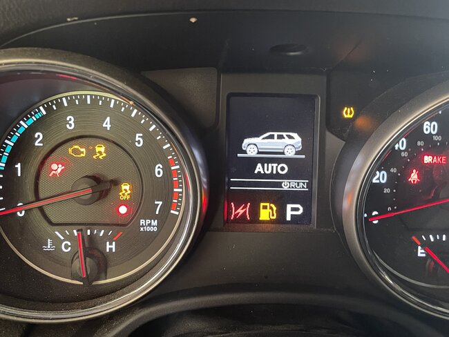
The vehicle listed above is a Cherokee Laredo. I parked the car for about 2 hours and when I came back, I started it and was idling for about 5 minutes while I was preparing to leave. I noticed a whirring noise and some smoke; I popped the hood and saw a red hot ember within the alternator so I got back in and reached for the start/stop button. As soon as I touched the button the battery light came on, i pressed the button and everything went black. I towed the car back home and proceeded to diagnose.
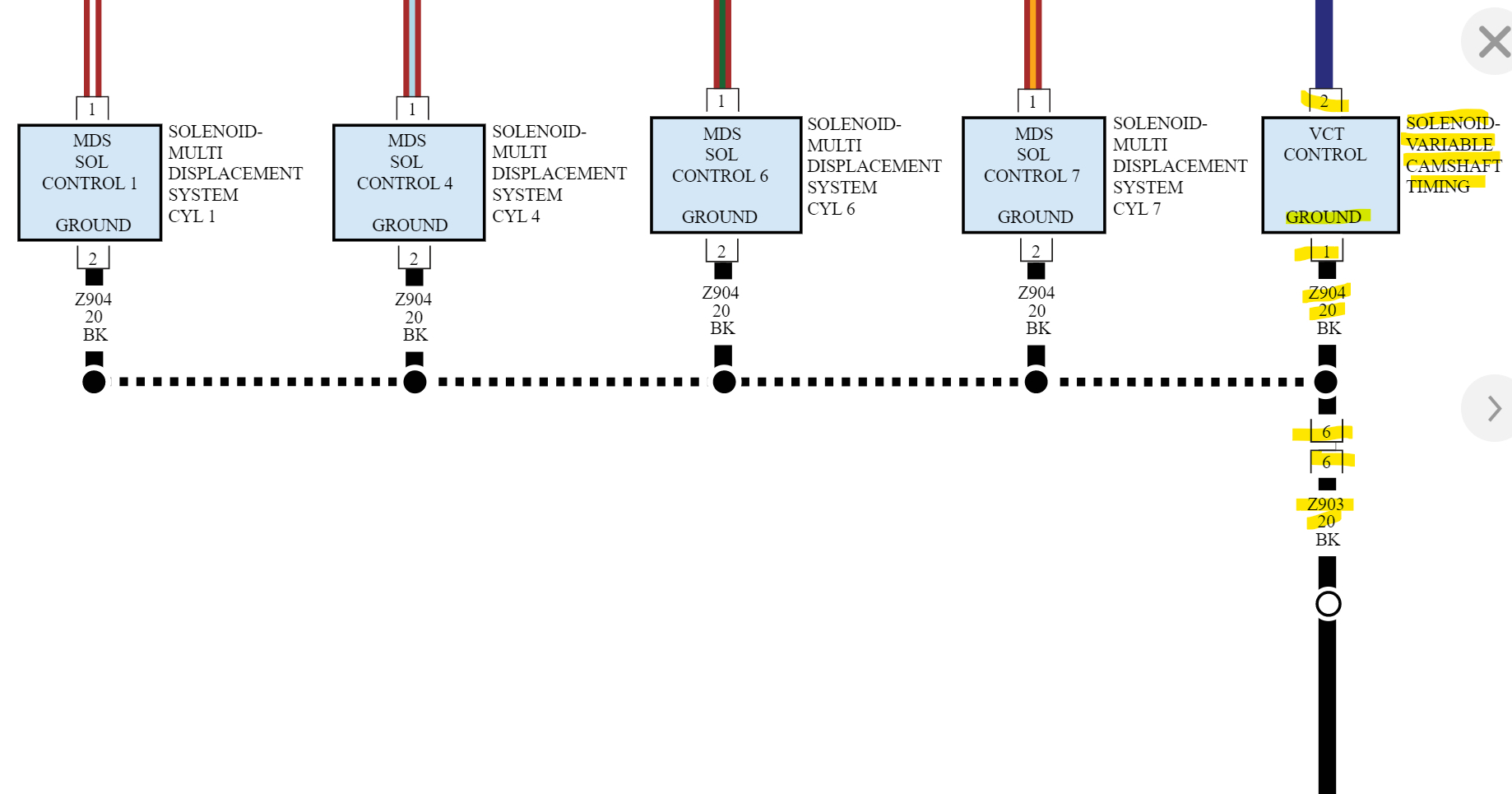
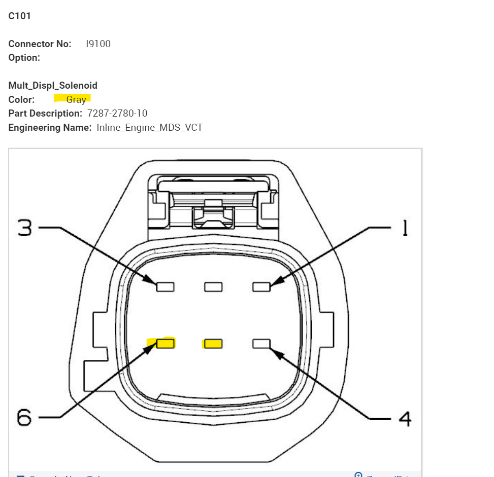
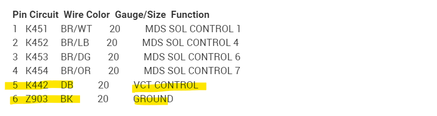
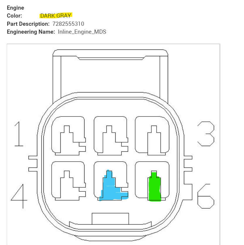
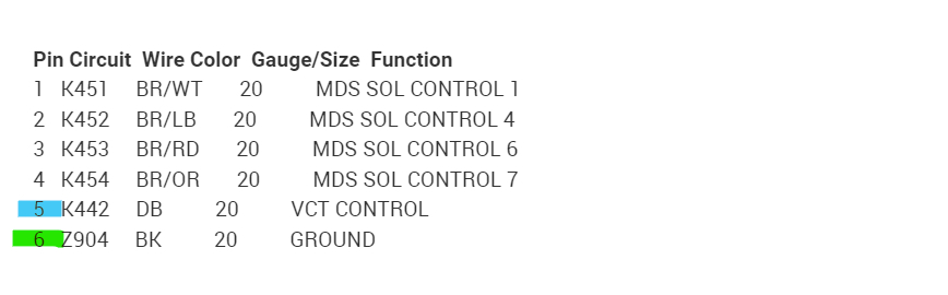
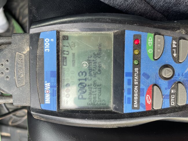
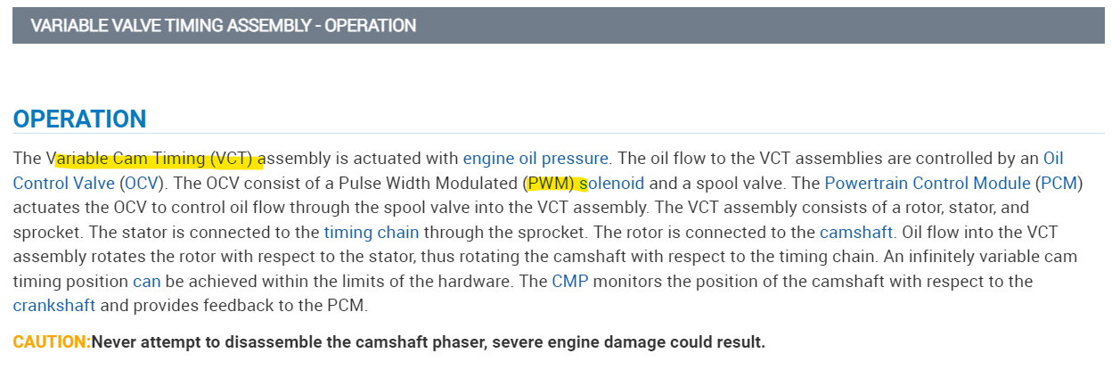
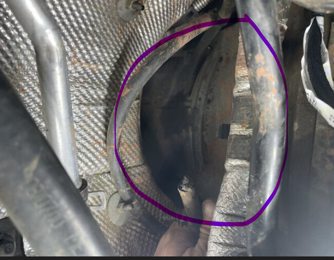
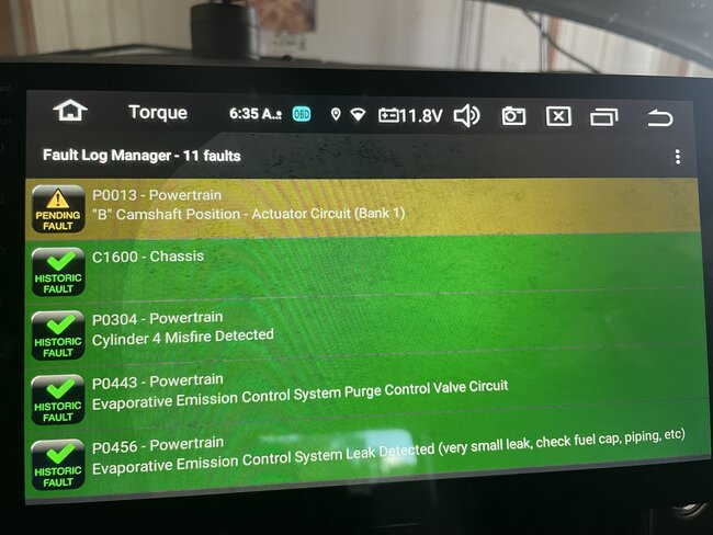
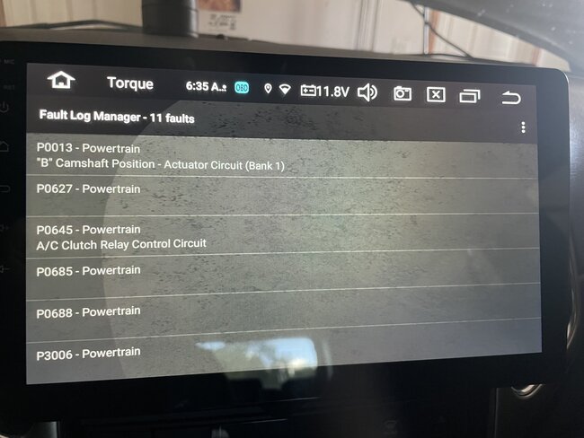
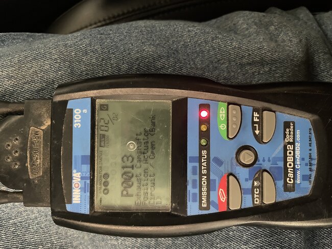
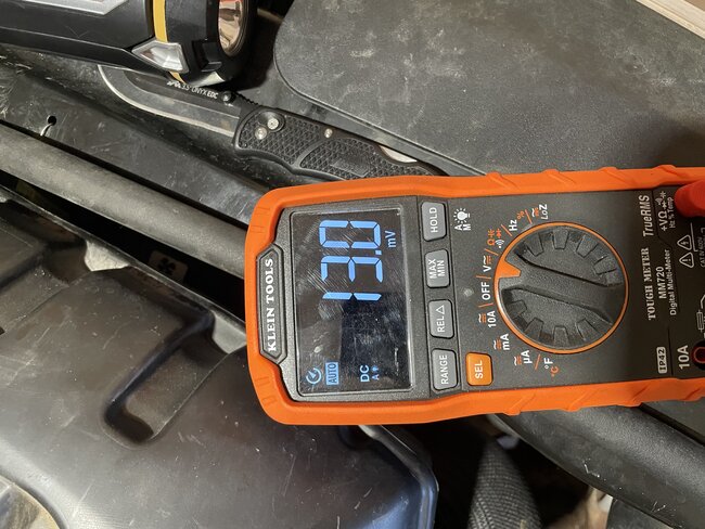
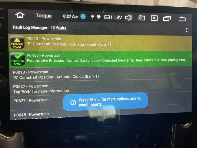
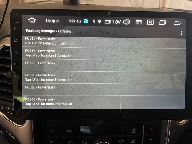
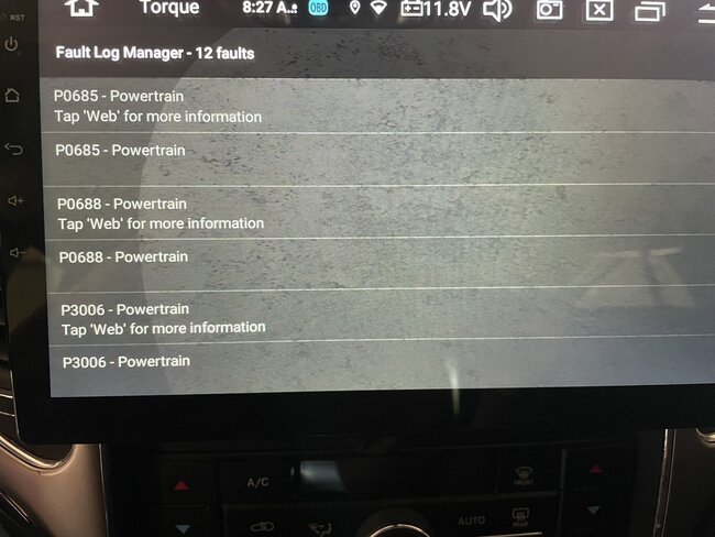
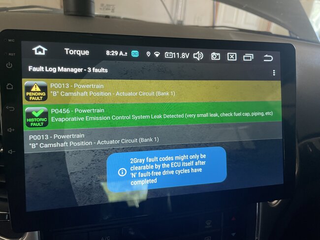
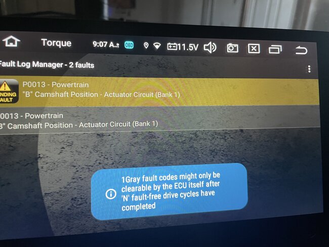
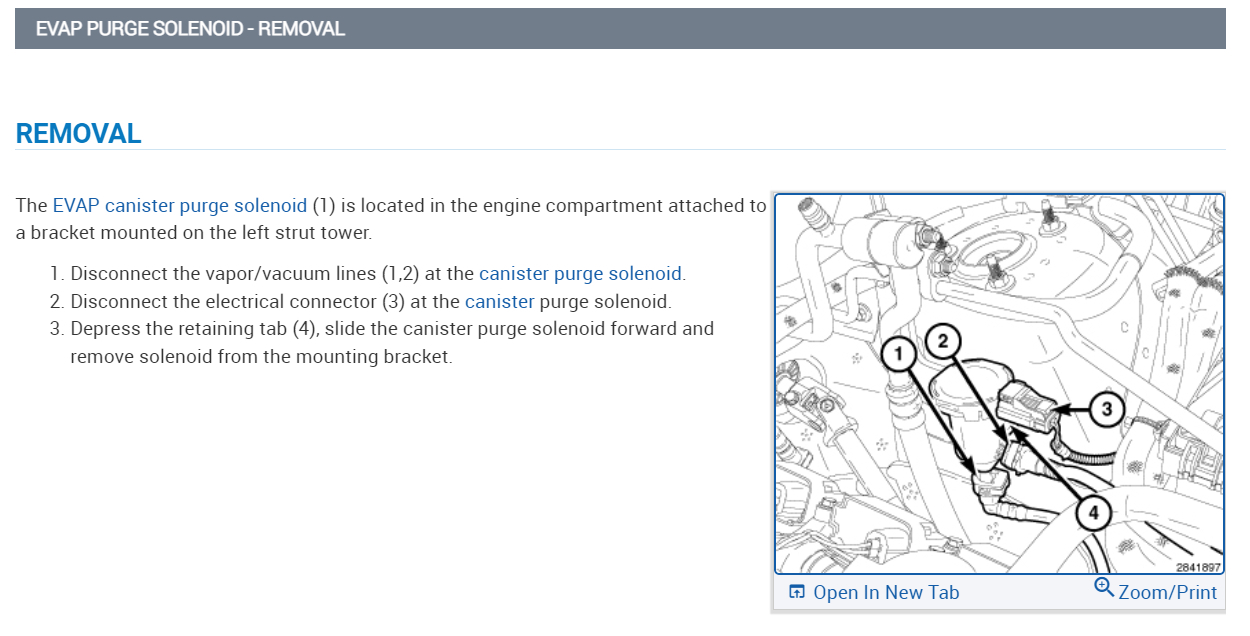
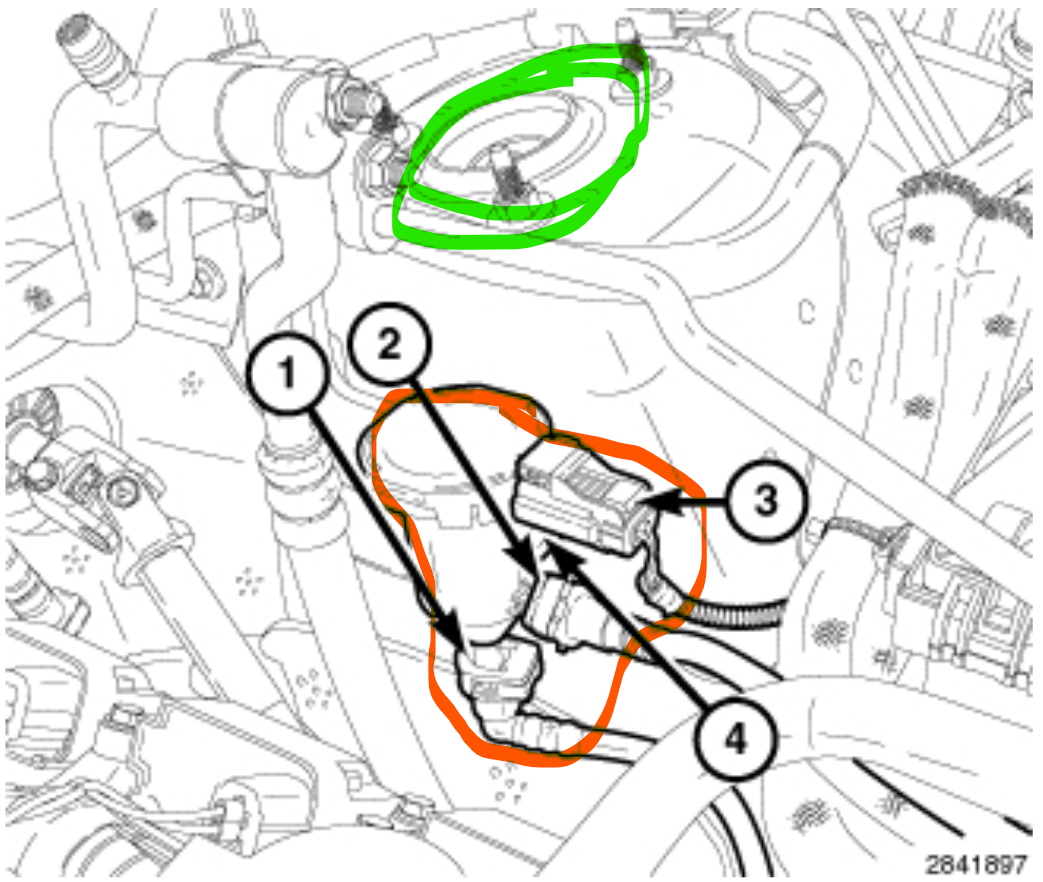
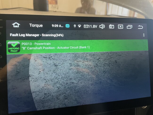
I replaced the alternator with a used one and put in a new AGM battery, started the car and was presented with a CEL. I put my Innova code reader on and got P0013: Exhaust Camshaft Position Actuator Circuit / Open Bank 1. I’ve been racking my brain to figure this out. I’ve pulled the intake manifold off and found bad/bare wires at the VVT solenoid, I repaired/mended the wires where it showed copper and ran continuities on both wires from before and after my mended spots, I then put the manifold back together. Started the car and got the same code. I pulled the manifold back off and pulled the VVT solenoid out. I ran a continuity test on the solenoid about 5 times and it was flat line, so I changed the multimeter to duty cycle and tested the solenoid, it was flat. I tested yet again on continuity, and it registered, every test after has registered with continuity. I put the solenoid to 12v to check for actuation, it actuates but I’m not sure if it’s fully opening. I left the whole thing where it is and ordered a new solenoid and jumper harness. I’m waiting on the new harness to arrive before I do anything further.

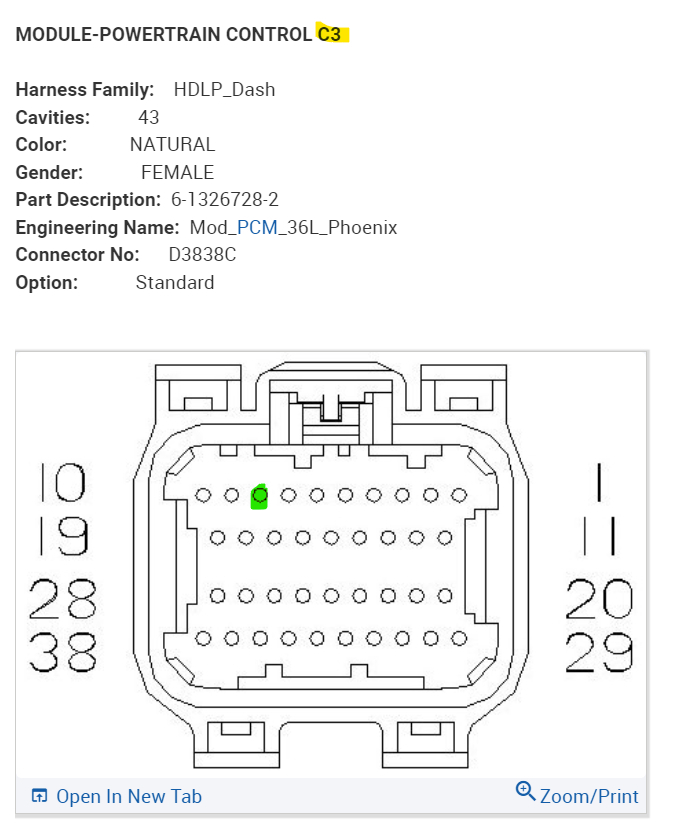
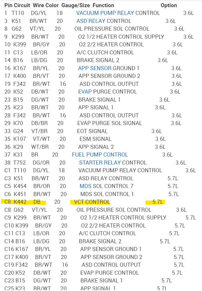
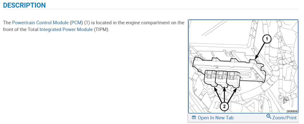
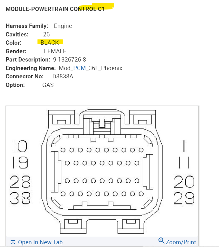
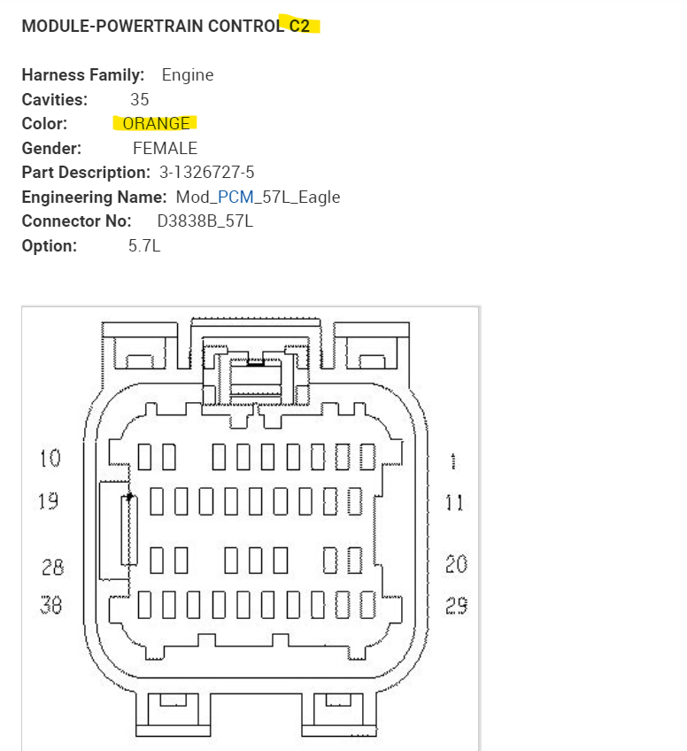
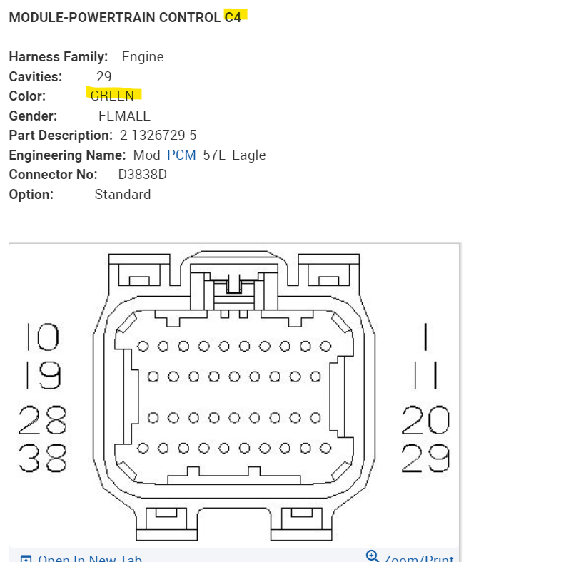
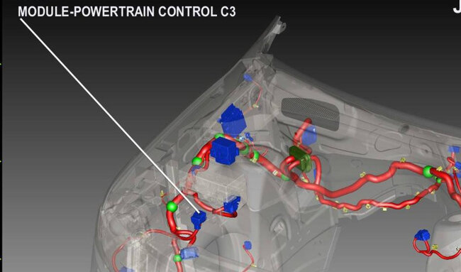
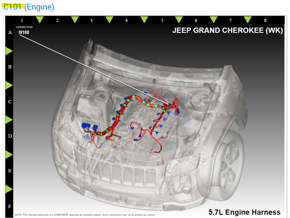
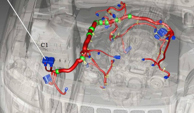
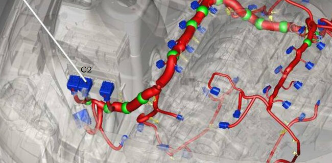
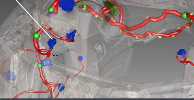
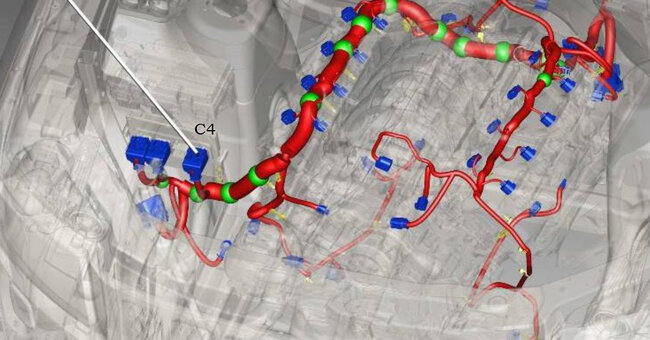
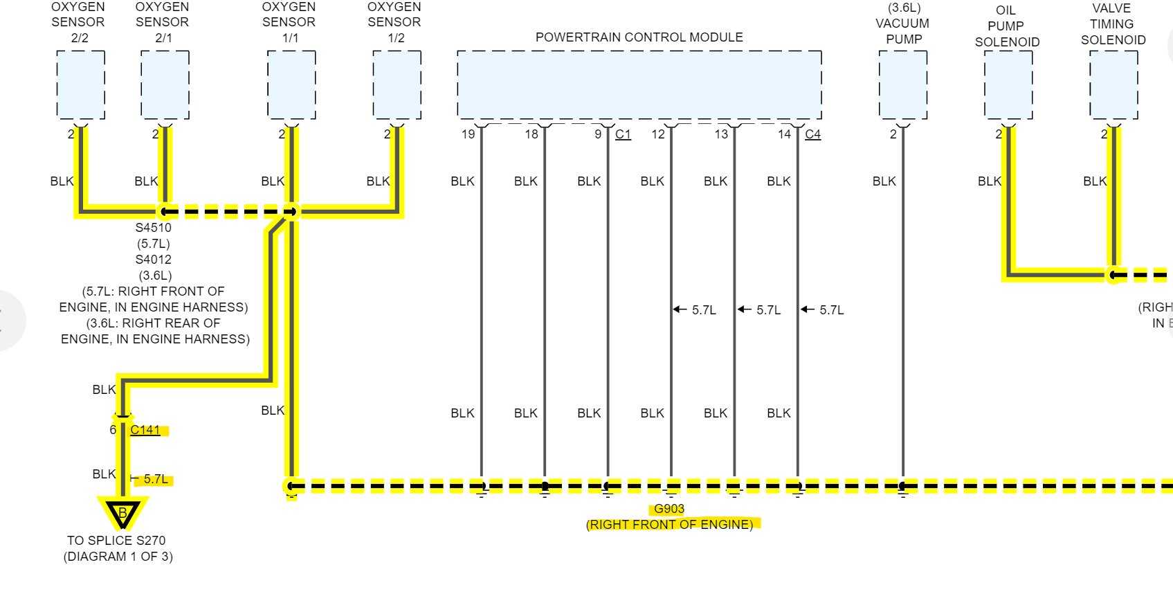
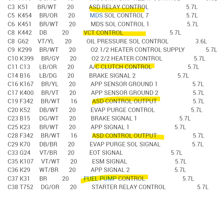
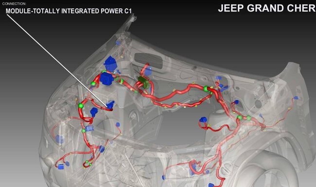
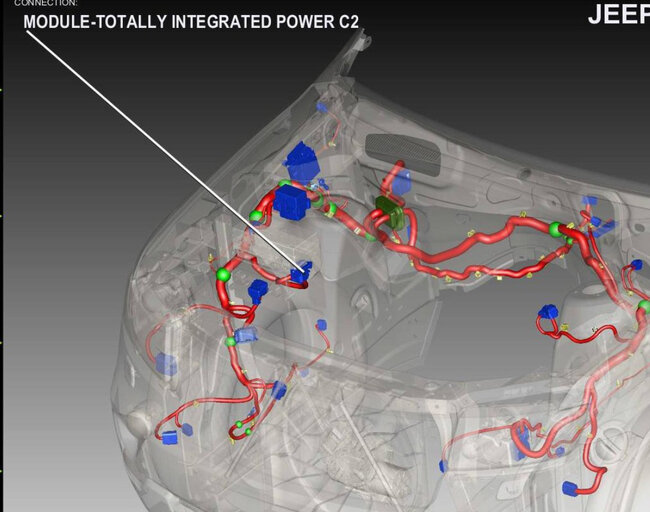
My question is how do I identify all the wires coming out of the PCM? It has 4 big plastic connectors coming out and lots of wires in each.
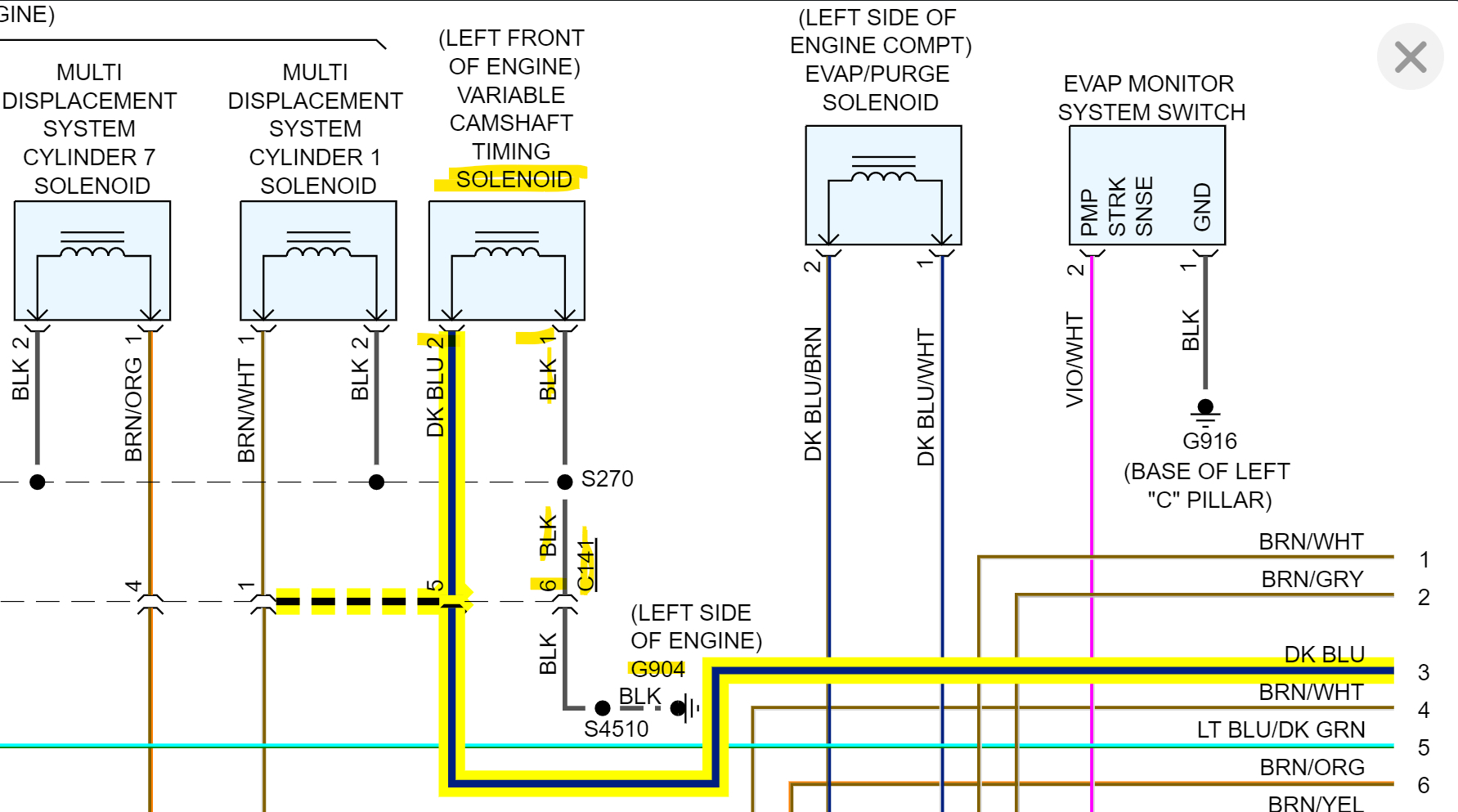
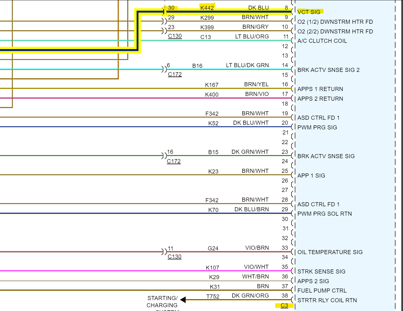
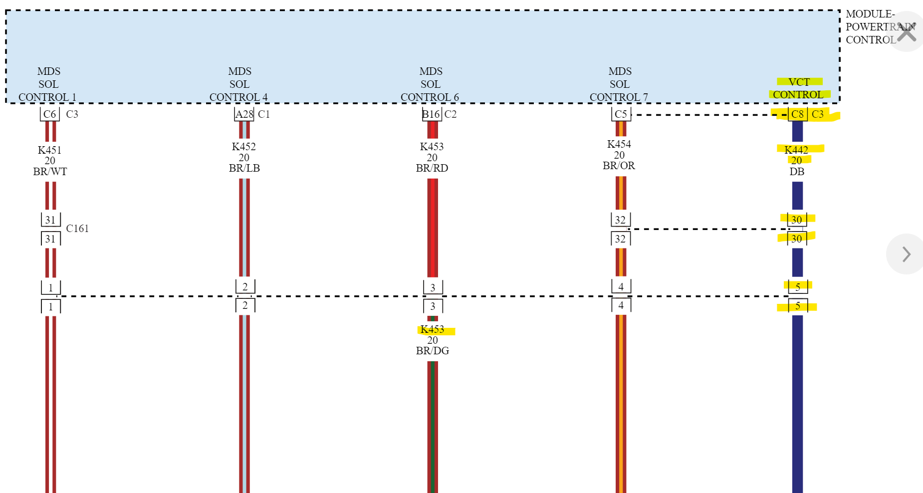
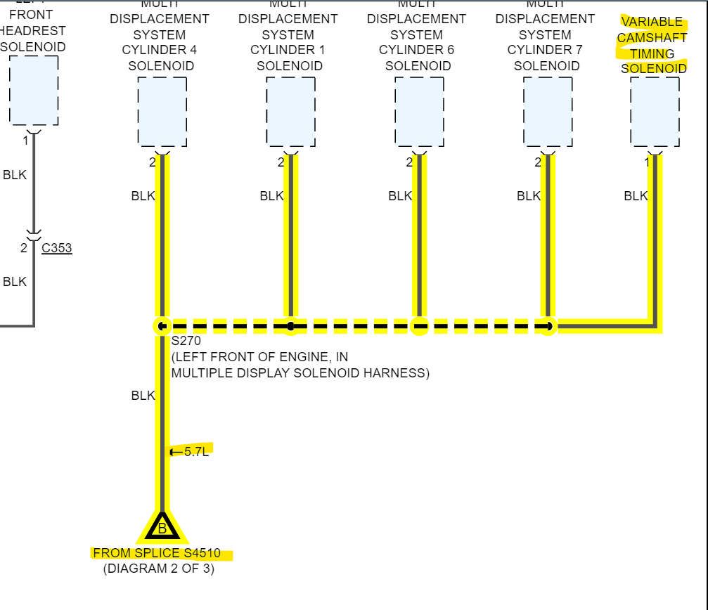
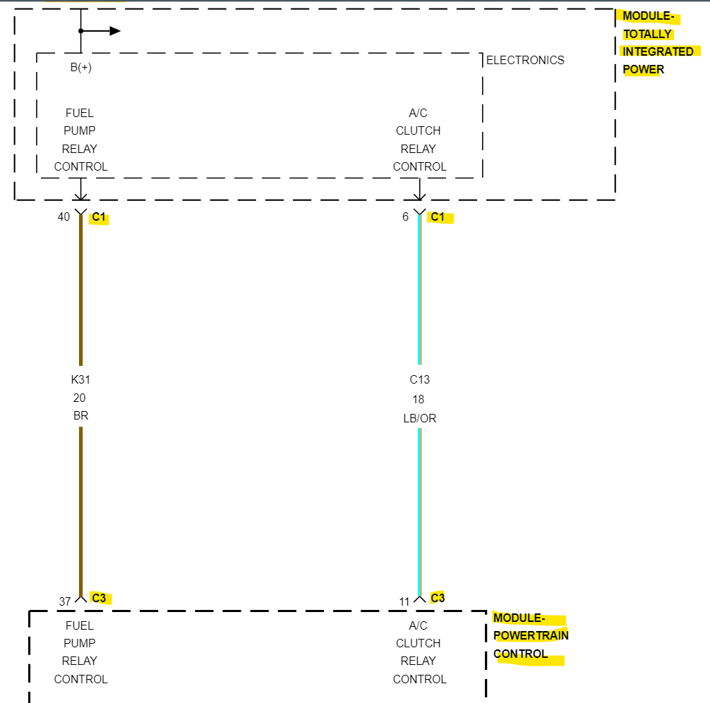
I have sourced a flow chart diagram of the engine electrical, but this doesn’t help me to single out the wires at the PCM side. My worry is that it’s a burn/broken wire further down in the jacket where I can’t see or reach, but if I can pinpoint the wires at the PCM side, I can in theory jump past the bad wire with a fresh wire, therefore saving thousands in repairs and having my vehicle running again.
May 27, 2023 at 11:23 AM
Advertisement
Avatar
LEPRIKAAN
  • MEMBER
  • 29 POSTS
Anyone?
May 28, 2023 at 6:02 AM
Avatar
AL514
  • CERTIFIED EXPERT
  • 5,464 POSTS
Hello, yes, we can pull up a wiring diagram for the ECM for you. Just going through the information, you provided. If the alternator was that hot inside, chances are that the diode set may have fried as well, but you won't have any AC voltage ripple now with a new alternator. Also, your assumption of further wire damage is most likely correct. Let me pull up the ECM diagrams for you.
Diagrams 1 to 8 are the flow chart for checking the rest of the circuit for shorts to Ground, shorts to power, and resistance in the circuit to the ECM, which I'm also getting the diagrams for, as well as the ECM connector C3 which is where the control wire for the solenoid runs to. It looks like this is a power side switched circuit, which I'm not sure why they would control it that way, but they did. Some of the flow chart tests you already did. But at least you'll have them, Hopefully the ECM driver for the solenoid didn't burn out.
May 28, 2023 at 1:12 PM
Advertisement
Avatar
LEPRIKAAN
  • MEMBER
  • 29 POSTS
Awesome, I appreciate all and any help I can get on this. I am basically stranded out in the mountains until I can get this whole thing fixed.
May 28, 2023 at 1:39 PM
Avatar
AL514
  • CERTIFIED EXPERT
  • 5,464 POSTS
Okay, refresh this page, I added some information in my last post.
Okay, ECM connector C3 pin 8 (dark blue wire) is the Solenoid control wire. I've added the other ECM connectors so you can find C3 easier, C1 is black, C2 is orange, C3 natural, C4 is green. Hopefully this service info is all correct.
But you can see in diagram 3, the solenoid has a constant Ground and is power side switched by the ECM. Hopefully they put a resistor inside the ECM to protect it from shorts to Ground but knowing Jeep they probably didn't. The 4th diagram shows the C3 connector pin 8 VCT SIG, there is that K442 connector and I also saw a C141 connector on diagram 3. I will see if I can locate that. But as for circuit testing, with the key Off, you can follow the flow chart and unplug C3 and check with your meter on Ohms setting for any continuity to Ground with the Solenoid unplugged. That will eliminate the ECM and solenoid for now and concentrate on the wiring alone to begin with. There is a key on test on Flow chart number 2. With this being a 2-wire circuit, it shouldn't be too difficult to trace down any other problem areas, I will post that C141 if its listed in service info for you.
I've added OEM diagrams 10 and 11 for you because I don't see a C141 connector listed.

Okay, they don't have this connector listed by C141, I know this is confusing, but they have it listed by circuit number,
Diagram 12 shows its location (C101) and diagrams 13,14 are one half of the connector,
and 15,16 are the other half of the connector.

They should be grey and dark grey in color, 6 pins, it's an inline connector that both the wires for the Solenoid run through. Still a dark blue wire (pin 5), and the Ground is black (pin 6).
May 28, 2023 at 1:44 PM
Avatar
LEPRIKAAN
  • MEMBER
  • 29 POSTS
Awesome information. I appreciate it more than you know!

I'm still unsure how to identify the PCM connectors. So, if I unplug them and look on the inside, they'll have color's or??
The outside of the housing is all black on all four. If the above is correct, when unplugged, the inside of C1 will have a black gromet and C2 will have an orange gromet etc...?
May 28, 2023 at 9:06 PM
Avatar
LEPRIKAAN
  • MEMBER
  • 29 POSTS
Also, is it safe to unplug the PCM connectors while the battery is disconnected? Will I need to resync anything for any reason, eg. I read that if I unplug the CMP sensor that it will have to be resync'd to the ECM or something to that end. I'm taking a guess and thinking the ECM is the same as the PCM. Again, I just can't be sure.


On a side note for later, while I have the manifold removed but resting in place, I was looking at the back side of the engine by the firewall for the ground, and found 2 black rubber hoses coming from the transmission that aren't connected to anything, they're just roaming around the engine bay loose like wild children. Can't for the life of me find a rhyme or reason to them but they're definitely attached to the trans, I can see one connection from the engine bay. The loose ends are rubbish, one has a hard plastic connector smelded into the tip, the other hose end looks like it's spent a life sentence in rubbing alcohol and is deteriorated/dry rotten. I can post photos if needed for any of the above.
May 28, 2023 at 9:21 PM
Avatar
AL514
  • CERTIFIED EXPERT
  • 5,464 POSTS
Each PCM connector itself should be a different color, but it might be referring to an inside grommet. I'm just going by the service information I have available. C3 should be the 3rd from the left I believe anyway, but you can verify C3 by checking some of the wiring colors if you're unsure. For example, pin C1 is a dark green wire with a yellow stripe.

The cam sensor issue you're thinking of is a cam/crank variation relearn procedure. That would need to be done if you replaced components, and the ECM needed to relearn the new positions of camshafts, crankshaft sensors, valve train parts, for example.

You're just going to be unplugging the one connector to verify there are no shorts to Ground or power that you can't see, instead of pulling the entire harness apart, you can do end to end testing and save a ton of time and headache. Since its really only going to be that one wire that controls the solenoid, you'll just be testing from the solenoid plug to the ECM plug. The Flow Chart should be very accurate. Sometimes they tend to have you doing tests that you may have covered already, because the flow charts are designed by engineers, not technicians. Some techs will do loaded voltage drop testing, but since you've already found some wire missing insulation, you know it's a possibility at this point for there to be more of that. You can see from the picture of C101, just about where the entire harness area you'll be needing to check is. From the back of the engine on the driver side to the ECM, I will also see if I can find this Ground location G904 if you have not already found it.

And that color for C3 being "natural", I'm sure is some tan type of color. And on the pinout sheet for C3 take note of where it says 5.7 Liter vs 3.6 Liter on the right side. If you want to post pictures of the rubber hoses you're referring to, that's fine.
May 29, 2023 at 10:35 AM
Avatar
AL514
  • CERTIFIED EXPERT
  • 5,464 POSTS
I want to make sure you these correct, do you have 4 ECM connectors or just 3? Some diagrams and pictures are showing the 5.7liter missing what looks like the 3rd connector over, but that might just be the service info.
This is what I'm seeing. Hopefully they're the same for you.
May 29, 2023 at 11:44 AM
Avatar
LEPRIKAAN
  • MEMBER
  • 29 POSTS
Yes, my PCM definitely has 4 plugins they appear to be symmetrical to each other and the body/housing is all black on all 4. I will unplug one to check for color and compare. Then I’ll check for continuity up to the plug after verifying colors/pins.
May 29, 2023 at 12:02 PM
Avatar
AL514
  • CERTIFIED EXPERT
  • 5,464 POSTS
Okay, the 3rd over should be the one you want. And not sure if i asked, but what scan tool do you have access to? Just wondering if you can pull up live engine data PIDs
Here is the Ground location for the timing solenoid.
May 29, 2023 at 12:14 PM
Avatar
LEPRIKAAN
  • MEMBER
  • 29 POSTS
This is the reader and the code. The Jeep itself has a reader built into the stereo but cannot access it while it’s all powered down.
May 29, 2023 at 1:40 PM
Avatar
AL514
  • CERTIFIED EXPERT
  • 5,464 POSTS
I don't see live data on that scanner. Let's see what you come up with during the harness testing.
May 29, 2023 at 2:54 PM
Avatar
LEPRIKAAN
  • MEMBER
  • 29 POSTS
I’m going to begin testing this morning. I am expecting the new jumper harness today, so I’ll disconnect the - and + battery cables, put the new jumper harness in and confirm C3 plug-in by checking color of grommet or by wire color verification. Then I’ll do a continuity test from the C3 pin 8 dark blue as well as the ground black. Does this sound correct?
May 30, 2023 at 8:17 AM
Avatar
LEPRIKAAN
  • MEMBER
  • 29 POSTS
Update: I ran the continuity test on both the blue and black from the solenoid end to the PCM plugin and to the shock bolt/ground as well as between the two at each end. Both wires have continuity but not between each other, although on the PCM plugin I couldn’t get continuity, I don’t know if my needle is long enough to make contact or if that pin is borked, so I needle probed the dark blue wire just below the plugin and got continuity. The new jumper harness will be delivered within the next hour. I will then replace the jumper and the solenoid, buckle the intake manifold back down, plug everything back in, connect the positive then the negative on the battery, check oil level and add if needed, then push the button to run mode and clear the code, then push the button to off and start the car, hold rpm above 1k for 1 minute and pray it doesn’t come back.
May 30, 2023 at 10:21 AM
Avatar
AL514
  • CERTIFIED EXPERT
  • 5,464 POSTS
You couldn't get a reading from the pin side of the PCM connector? Can you see the pin inside the connector? I would be concerned that the C3 connector pin did back itself out somewhat, that could happen if that wire got hot. Possibly from those wires shorting out. So, if you can, verify that front pin, pin fitment issues can cause you to chase issues for a long time. With those connectors being hooked up for so many years of usage. And they get hot and cool down and that's how pins don't make contact anymore. And really you have no way to monitor the ECM data to see if the cam timing is changing. What you could do is to monitor that wire with your multimeter after you get everything back together. It's most likely going to be a pulse width modulated circuit, so you will see an average voltage with the multimeter and not a full 12volts all the time. If it's 50% duty cycle, 50 on 50 off, you would average 6ish volts because a meter can only average that voltage. If you were to scope that wire, you would see a 0v to 12volt square wave signal. That would vary depending on how much the ECM is changing the cam timing. But I would really check that ECM connector. With the testing you did on the solenoid, it sounds like it over heated and that's why you got those odd readings.
Solenoids are controlled by PWM to prevent them from overheating. I'd feel bad if that code came back after all the work you have done already. It's really great. Those ECM connectors do come apart if that pin has backed out. They take some time, and you have to be careful with them. Or you could try the pierce again on the dark blue wire and then right to the ECM pin to check continuity. That way at least you'll know that connector has a pin fitment issue.
May 30, 2023 at 12:14 PM
Avatar
LEPRIKAAN
  • MEMBER
  • 29 POSTS
Okay, I have everything back together minus the battery cables. I took another look at the PCM plugin side and realized I should’ve been trying the 3rd from the left not the right. It’s a little bit late now but I installed the new solenoid and jumper harness. I plugged everything back in as far as I can tell, doing a double check as I type now.

Before I go any further, I’m wondering what you think my next steps should be.

Also, here are the pictures of the rubber lines coming from the transmission that are messed up.
May 30, 2023 at 12:48 PM
Avatar
AL514
  • CERTIFIED EXPERT
  • 5,464 POSTS
I'm not sure what those lines are. I thought maybe at first it was some overflow type line, but it does look like there is a plug in that one end. I'll take a look on all data for any transmission diagrams. I'd say you can start it, let it get up to operating temperature and see if you notice anything abnormal happening. Ill post what I find on the transmission.
Also on your wire checking, there was the black wire grounded for the Solenoid.
I don't see those being any kind of transmission cooling lines, being rubber like that.
May 30, 2023 at 1:49 PM
Avatar
LEPRIKAAN
  • MEMBER
  • 29 POSTS
Yes, I checked the ground wire for continuity by probing the wire at the solenoid end and touching the strut/shock mount bolt. I will clear the code and start it now.
May 30, 2023 at 1:51 PM
Avatar
AL514
  • CERTIFIED EXPERT
  • 5,464 POSTS
Is this the transmission bell housing?
May 30, 2023 at 1:58 PM
Avatar
LEPRIKAAN
  • MEMBER
  • 29 POSTS
Yes, it is.
I cleared the code, and the light comes back with the same code. I’m going to let it get warmed up to operating temperature which I would assume is about 200, 210, and see what happens. I’ll post back ASAP.
May 30, 2023 at 2:05 PM
Avatar
AL514
  • CERTIFIED EXPERT
  • 5,464 POSTS
Still P0013? This isn't a Natural Gas vehicle, is it? You can try your pierce tool and clear the code, have a test light or multimeter hooked up to the dark blue wire right at the PCM and start the vehicle, see if you're getting any voltage out of that wire. But you will have to do this quickly, once the code is set it will probably disable that circuit. Being that it is a circuit code, there is a voltage issue somewhere. We need to know if there's any voltage coming out of the ECM to command that solenoid.
I'm also wondering about a cam/crank relearn procedure needing to be done.
May 30, 2023 at 2:30 PM
Avatar
LEPRIKAAN
  • MEMBER
  • 29 POSTS
No it’s unleaded 5.7 hemi.
It warmed up to temp then just shut off.
Yes the code is the same. I cleared the code then started the car again and it shutdown again. Here are pictures from after I cleared the code and it came back. This is from the torque app on the head unit.
May 30, 2023 at 2:40 PM
Avatar
LEPRIKAAN
  • MEMBER
  • 29 POSTS
I also see this lightning symbol in the dash, it blinks about 3 times then goes away.
May 30, 2023 at 2:52 PM
Avatar
AL514
  • CERTIFIED EXPERT
  • 5,464 POSTS
You have 11 codes set now?
May 30, 2023 at 2:57 PM
Avatar
LEPRIKAAN
  • MEMBER
  • 29 POSTS
The Innova code reader only shows the 1 code, P0013. The Torque app shows those other codes and the orange is pending, the green I assume are ok because the check mark and the grey it says will be cleared with so many Drive cycles.
May 30, 2023 at 3:04 PM
Avatar
AL514
  • CERTIFIED EXPERT
  • 5,464 POSTS
Well, with the stalling now, I think i know what's going on, I looked up 4 of these codes, P0627 Fuel Pump A Control Circuit open
P0645 AC Clutch Relay Control Circuit open
P0685 PCM Power Relay Control Circuit open - This I assume is the ASD Relay
P0688 PCM Power Relay Sense Circuit open

But all these components- Control circuits are in the PCM C3 connector.
But also, PCM C3 goes to C1 of the TIPM (2nd diagram). I'm not sure if you had unplugged any of the TIPM connectors, but this might be a connector issue since these problems were not there as far as we know before the repair
I would stick with the Torque scan tool for now, I think Torque also has live data. Are you using the ELM 327 with the data link connector?
Looks like Electronic Throttle control.
May 30, 2023 at 3:13 PM
Avatar
LEPRIKAAN
  • MEMBER
  • 29 POSTS
I’m not sure if it’s elm327, here is the link to the one I’m using.
Friencity OBD2 Scanner Adapter Bluetooth, Wireless Diagnostic Code Reader OBD II Scan Tool Reset & Clear Check Car Engine Light, Compatible with Android & Windows (NOT for iOS) https://a.co/d/1kEpy2K

I did check all of the fuses for bad ones but didn’t find any. TIPM is basically the fuse box correct?

I did check for voltage using the multimeter and test light. The light didn’t come on so I tried the multimeter. I took a picture, but when the car started, the voltage spiked to 30 something, and then started dropping. I got the picture at 13 volts, but when the car shut down again, and it dropped to 11.4.
May 30, 2023 at 3:51 PM
Avatar
AL514
  • CERTIFIED EXPERT
  • 5,464 POSTS
The TIPM is more like a smart junction fuse panel, it has canbus data network circuits and works with the PCM. I dent like a 30volt spike, it's possible that is due to the solenoid transient shut off voltage. But I think the stall out issue has more to do with these codes, try clearing them all, and check that C3 is connected fully. These TIPM connectors look to be on the underside of the module, if you can see in the diagrams 1,2 below. I'm not sure how much those connectors got moved around during testing. After you clear the codes and check the connectors, let's see which codes come back first. It's clear the ASD Relay is powering down, that's powering down the PCM, and it's a domino effect of power loss. Hopefully this is just a connector pin issue. Diagnosing a failed TIPM is going to be very difficult.
There is a recall on the Fuel pump relay inside the TIPM failing causing a stall condition, but that doesn't make much sense since the vehicle ran before the solenoid replacement

If you can pull up any live data on the Torque for the PCM, it would help to see what is cutting out first. The TIPM has integrated circuit boards and power bus bar. And it can also set trouble codes itself. They won't be P codes; it will be more of U or B type codes.
May 30, 2023 at 4:36 PM
Avatar
LEPRIKAAN
  • MEMBER
  • 29 POSTS
I opened the torque app and got these codes in images one through three. I cleared the codes, and the app said some vehicles require immediate start when the clear command sent. So as soon as I saw the clear command, I started the engine and waited for the check engine light. When the check engine light came on I ran a fresh skin and got these codes in image four.
May 30, 2023 at 5:03 PM
Avatar
AL514
  • CERTIFIED EXPERT
  • 5,464 POSTS
Battery voltage looks too low in these scans, did it stall out or are these scans just key on engine off? These PCM power relay codes 685, 688 are the concerning point, for some reason the ECM or TIPM is shutting down the ASD relay and then the PCM is detecting that power failure (p0688 power relay sense circuit). You might try shutting everything down, unplug your scan tools and unhook the battery negative for a few minutes and see what happens. If your battery has a battery current sensor on the negative post make sure not to over tighten the clamp. Some of the TIPMs fuses might be encased and need a close look at to verify they aren't burnt. Can you reach the cam timing solenoid you replaced? or is that under the intake? This has to be some kind of connection issue.
This vehicle has a wireless ignition node (module), maybe that scan tool is interfering with some communications on the data link connector.
May 30, 2023 at 5:21 PM
Avatar
LEPRIKAAN
  • MEMBER
  • 29 POSTS
The scans are with engine off and ignition in run. The car is stalling out too soon to complete a scan with it running. On my first running test it ran for about 15 minutes before shut down. I can’t reach the solenoid, it is under the intake. I don’t see any kind of sensor on the cable or post of the battery. What do you mean the fuse might be encased? And what fuses should I be looking for? On another scan just now the 11 codes are up again. I will disconnect the negative cable for a few minutes and try clearing codes again, restart the engine and wait for the CEL, run the scan again and post the results.
May 30, 2023 at 5:30 PM
Avatar
AL514
  • CERTIFIED EXPERT
  • 5,464 POSTS
There looks like there is another power distribution center with some higher amperage fuses, usually those are in small plastic cases. I would check all the fuses in the vehicle you can find. Ive been looking through service info for any procedures after a battery disconnect, but havent found any. With codes setting like they are, the only logical explanation is that some connection has been disturbed. If it was something to do with the anti theft or alarm system it wouldnt be setting those codes. And that you had a successful start up for 15min. Ill ask some other technicians what they think might be going on. It seemed like a simple enough repair. The only thing that comes to mind is harness connections.
Did you have any issues with stalling before the solenoid replacement? Or no start, or just this code setting (p0013)?
And out of the 11 codes, were there any for security system issues?
Ive posted the vehicle on a forum for All Data, lets see what some others have to say on the situation.
May 30, 2023 at 6:07 PM
Avatar
LEPRIKAAN
  • MEMBER
  • 29 POSTS
Here is the results after removing the negative battery cable. I ran a scan right after reconnecting the negative cable and it’s the first picture. I cleared the codes and started the car and this is the result in the second picture. The third picture is the live data screen. I never had any kind of issue until the alternator problem. No security issues either.

I was suggested to look at the CMP sensor and it’s harness as well, I have looked at its physical location and it’s in the front of the engine in the right side of the timing case. I unplugged the wire from the CMP to look for damage, I found none so I plugged it back in. Could the CPM or its harness be the culprit or part of it?.
Is it possible to change the CMP sensor without having to have the computers relearn with a diagnostic tool?
May 30, 2023 at 6:36 PM
Avatar
AL514
  • CERTIFIED EXPERT
  • 5,464 POSTS
So, you're not getting any of the other codes you had on earlier scans? And yes, I was going to mention the cam sensor, but that was kind of useless at the point where it wouldn't run. Another possibility is that those wires shorted out and took out the ECM driver for the cam timing solenoid. I have seen Jeep ECMs take out drivers many times because of circuit design like this., If you do try a cam sensor, you'll have to do a cam/crank relearn procedure. But since this is a circuit code, you can try a new cam sensor and see if that specific code comes back (p0013). Since you don't have a scan tool with special functions right now, there is no way to do a crank relearn. But since the beginning of this, especially with the alternator issue, I was worried about that ECM driver, but you did have voltage there in the after the repair. Does the vehicle run now without stalling?

I was hoping that the live data would have more specific data PIDs like cam timing "Actual" and "Desired" and that would tell us if the timing was able to change or not.
I'm going to look up more info on the cam sensor, because I don't think the vehicle would start at all if the cam sensor was not working, but I don't know how many this has either, so ill check that right now.,
May 31, 2023 at 9:41 AM
Avatar
LEPRIKAAN
  • MEMBER
  • 29 POSTS
No, it runs for a few minutes and stalls out completely, total RPM drops, and the dash display changes a bit and looks like it’s on the run position. It runs for longer if I remove the battery cable, wait a few minutes, then replace the battery cable and start it. Seems to run longest when it’s the first start and cold.

Would a new/used alternator make the problem persist if it was a bad alternator? The alternator I put in is used.
May 31, 2023 at 9:49 AM
Avatar
AL514
  • CERTIFIED EXPERT
  • 5,464 POSTS
It depends on the condition of the alternator, but what initially happened with the old alternator could have potentially damaged the TIPM, they are known for failure. The code that is setting is camshaft position actuator circuit open code, but we are limited here on options. You don't have a scope or any to monitor position sensors, this vehicle only has 1 cam position sensor. It's a 0 to 5volt three wire sensor, so it's a hall effect sensor that will make 0-5volt square wave signals to the ECM in time with the crank position sensor. Since its still stalling out you can try blocking off the Purge valve and see if that will stop the stalling, You do have the historic Evap code, If there is a vacuum leak through the evap system, and the Purge valve is still being turned on, that might account for the stalling and it worth a try, I'm pulling its location right now, give me a sec.
In the 2nd diagram in Green is the strut tower on the driver side, and the Purge Valve is what the ECM uses to pull vapors into the intake manifold. You can try unplugging it first (electrical connector), and if it still stalls you can take a line off coming to the purge valve and block it off, this is just a shot in the dark. But technically the engine could start purging the tank a few minutes after start up.
Next, we would just have to try a cam sensor,
May 31, 2023 at 9:59 AM
Avatar
AL514
  • CERTIFIED EXPERT
  • 5,464 POSTS
Refresh this page again and it will show my last posts.
That Battery voltage is still reading low, I'm not sure if that data is after the stall out or not, but it doesn't seem to be charging correctly either. I don't think 11.8v will shut down the vehicle, but that alternator may have done more damage than we know. If the AC voltage ripple got high enough it could definitely damage the PCM or TIPM. There might be multiple problems here.
May 31, 2023 at 10:05 AM
Avatar
LEPRIKAAN
  • MEMBER
  • 29 POSTS
I’ll try the purge and see it it helps keep it running longer than the warm-up. I’m not sure about changing out the cam sensor as I don’t have access to the computer for relearning.
That voltage does seem low so I could put a multi meter to the alternator to test that. I did multi meter the battery and it was at 12.2 V not connected. I didn’t test it again after I started the car.

After connecting the battery, put the ignition in run mode and did a scan on the codes came back with only one fault code in the first picture, I cleared the code and started the car, and the cel came back, so I did another scan with it running, and it came back with only the one code in the second picture.

I’ll post back with results of testing the purge system.
May 31, 2023 at 10:52 AM
Avatar
AL514
  • CERTIFIED EXPERT
  • 5,464 POSTS
Yeah, the ECM is able to monitor the voltage on that solenoid control circuit, its seeing an issue right when you turn the key on. So, there is still an issue on that cam timing circuit, but that really shouldn't cause it to stall out. It might need a number of key cycles before it can set any of the other codes, since it's probably not running long enough or another possibility is the charging system voltage, check that while its running, leave the multimeter right on the battery when you start it up, That way you can see how low the battery drops during start up and catch the charging system voltage before it stalls out. It's really difficult to tell what is happening, not being at the vehicle with you. Do any warning lights come on the dash just before the stall out?
May 31, 2023 at 11:15 AM
Avatar
LEPRIKAAN
  • MEMBER
  • 29 POSTS
I had an emergency come up and have to stop until tomorrow. As soon as I’m back with the vehicle I’ll try the purge system and post back. I apologize.

I haven’t seen any warning lights other than the CEL and the lightning bolt when the ignition is in the run position. When it stalls, it just goes flat. No bells or lights, rpm’s just drop to 0 and the engine is off by the time the tach hits bottom.
May 31, 2023 at 1:50 PM