codes

2000 SATURN L100
101,000 MILES • 4 CYL • FWD • MANUAL
Avatar
LALFAN
  • MEMBER
  • 179 POSTS
i have a 00 saturn ls2 wiyh a code p0742. would like to know what this might amount to. it seems like sometimes it dont want to shift into od when it should. thanks
Mar 3, 2011 at 10:21 PM
Advertisement
Avatar
SATURNTECH9
  • CERTIFIED EXPERT
  • 30,869 POSTS
So you have the v6 3.0L engine in your car?You said you have a 2000 L100 then you say you have a Ls2 a little confusing.I just want to know what car were talking about so i can give you the correct info.
Mar 3, 2011 at 10:46 PM
Avatar
LALFAN
  • MEMBER
  • 179 POSTS
it is a ls2. the part you click on when you fill this out doesnt have a ls2. sorry
Mar 3, 2011 at 11:20 PM
Advertisement
Avatar
SATURNTECH9
  • CERTIFIED EXPERT
  • 30,869 POSTS
So do you have any other code's besides the P0742?Iam posting the code description and a bulletin i found for that code.

The Torque Converter Clutch Solenoid Valve (TCC So. Valve) is a pulse width modulated solenoid. When vehicle operating conditions are met for TCC application, the PCM/TCM begins the duty cycle at approximately 42% . The PCM/TCM then increases the duty cycle up to 90% in order to achieve full TCC apply. When the TCC Sol. valve is de-energized, the solenoid blocks filtered 2-3 drive fluid, and allows TCC signal fluid to exhaust. When energized, the solenoid modulates fluid into the TCC signal fluid circuit. When fully energized, modulation stops, and the solenoid blocks both 2-3 drive fluid and TCC signal fluid exhaust.

The TCC release switch is a normally closed switch. It signals the PCM/TCM the TCC is released. Torque converter release fluid pressure acts on the switch contact, opening the circuit. When the voltage on the circuit is high, the PCM/TCM recognizes the TCC is no longer engaged.

When the PCM/TCM detects the TCC release switch is closed when the TCC is commanded OFF, then DTC P0742 sets. DTC P0742 is a type A DTC.

DTC PARAMETERS

* Engine is running
* TPS greater than 8%
* Trans fluid temperature between 21°C (70°F) and 130°C (266°F) .
* Engine torque greater than 40 ft-lbs
* Gear ratio 3rd or 4th
* TCC is commanded OFF
* No TPS, TFP, VSS, ISS codes
* No TCC stuck ON code
* No TCC electrical code
* No TCC release switch code
* No engine torque default
* Time since last manual range change greater than 6 seconds

DIAGNOSTIC AIDS
Inspect and repair as necessary:

* TCC Sol. valve exhaust restricted.
* TCC Sol. valve filter plugged.
* TCC control valve stuck in the applied position.
* TCC regulated apply valve stuck in the applied position.
* TCC feed limit valve stuck.
* Pressure regulator valve stuck.
* TCC fluid circuit leaks.
* TCC release switch for damaged or leaking seal, debris in switch, damaged switch contacts, stuck switch contacts.


Bulletin No.: 07-07-30-025

Date: October 01, 2007

INFORMATION
Subject:
Information On 4T40-E (MN4) and 4T45-E (MN5) Front Wheel Drive Automatic Transmission Valve Body Reconditioning, DTC P0741, P0742, P0751, P0752, P0756, P0757, P1811, Harsh Shifts, Slips, No Drive, No Reverse

Models:
1997-2005 Chevrolet Cavalier
1997-2007 Chevrolet Malibu
2005-2007 Chevrolet Cobalt
2006-2007 Chevrolet Malibu Maxx, HHR
1997-1998 Oldsmobile Cutlass
1999-2004 Oldsmobile Alero
1997-2005 Pontiac Sunfire
1999-2005 Pontiac Grand Am
2005-2006 Pontiac Pursuit (Canada Only)
2005-2007 Pontiac G6
2007 Pontiac GS
2000-2005 Saturn L-Series
2005-2007 Saturn ION, VUE
2007 Saturn Aura

with Hydra-Matic(R) 4T40-E (RPO MN4) and 4T45-E (RPO MN5) Automatic Transmission

The following new service information outlined in this bulletin will aid technicians in providing easy to follow valve body reconditioning instructions and new illustrations to simplify reassembly of the valve body. The service bulletin will also provide additional service information documents that are related to the 4L6x transmission family.

Related Service Documents

PIP 3253B - No Move Drive or Reverse

02-07-30-039F - Firm Transmission Shifts

02-07-30-050 - Engineering Change Valve Body

If valve body cleaning is not required, Do Not disassembly bores unless it is necessary to verify movement of valves.

Inspection Procedure

Using the exploded views in this bulletin, inspect each bore for freedom of valve(s) movement and evidence of debris. Pay particular attention to those valves related to the customer's concern.

Verify movement of the valves in their normal installed position. Valves may become restricted during removal or installation. This is normal due to small tolerances between the valves and bores.

If a valve is restricted and cannot be corrected by cleaning valve and bore, then replace valve body. Describe restricted valve on repair order.
Be sure all solenoids are installed with the electrical connectors facing the non-machined (cast) side of the valve body; otherwise, the solenoids will bind against the transmission case as the valve body bolts are
tightened and damage may occur.

Disassembly/Reassembly

If a valve is restricted by a metal burr from machining that bore, remove valve and burr, then inspect movement in the valve's normal position. If no other debris or restrictions are found, then reassemble valve body and install in the transmission.

If the valve body has been contaminated with debris from another transmission component failure, then disassemble all bores for complete cleaning of all valve body components. If possible keep individual bore parts separated for ease of reassembly. Use the following illustrations in this bulletin for a positive identification and location of individual parts:
Mar 3, 2011 at 11:38 PM
Avatar
LALFAN
  • MEMBER
  • 179 POSTS
only other code for trans was a code for park neutral switch tha t i think is on top of trans. is most of the parts in the valve body or everywhere in the transmission. it did seem to have a little slip sometimes my daughter said. i see it has a little leakage on some lines that come out the front side. not sure how bad. dont know when the filter has been changed last. so could be electrical parts mostly.
Mar 4, 2011 at 12:03 AM
Avatar
SATURNTECH9
  • CERTIFIED EXPERT
  • 30,869 POSTS
The solenoid's are in the valve body under the side cover of the transmission.It could be a bad solenoid or plugged solenoid.The neutral safety switch is on top of the transmission connected to the shift cable.What is the exact code number for that switch?The fluid on that car should be changed every 50,000 mile's.I would drop the transmission pan to see how much debris in the pan.Also look for shinny flake's that would be metal debris.You have to have the fluid drained to pull the side cover off as well so keep that in mind.
Mar 4, 2011 at 5:42 PM
Avatar
LALFAN
  • MEMBER
  • 179 POSTS
the code for the switch is p1780. i have a cheap book that does not cover transmissions. so i have to take a side cover off for the valve body. i will have to look cause i dont even know what side at this point.im going to a junk yard tommorrow and thought about trying to pull one. worst problem is not knowing what i will get. is it hard to get one out and does anything fall out when you remove them. so i dont loose anything. have never worked on one like this, just older cars. will have to put in new filter and fluid and hope for the best. should be able to get a different switch for on top. give me any info or diagrams you can on this project if you would. thanks craig
Mar 4, 2011 at 10:21 PM
Avatar
SATURNTECH9
  • CERTIFIED EXPERT
  • 30,869 POSTS
I have replaced very few valve body's on those car's it's usually a bad solenoid or some debris.If you take off the valve body there spring's etc that will go everywhere.The side cover is on the drivers side it's pretty big hard to miss.I would start by seeing how much debris in the pan and go from there.


Circuit Description

The engine control module (ECM), transaxle control module (TCM), and the body control module (BCM) communicate with each other over the controller area network (CAN) BUS circuits 2500 and 2501. The CAN BUS is a communications protocol that is used by the TCM to communicate vital engine control inputs from a stand-alone engine controller. The diagnostic checks the information received in CAN to determine whether to pass or fail a code. Before checking the information, the TCM makes sure the CAN messages are being received by checking the BUS failure timer.

Conditions for Setting the DTC

DTC P1779, P1791, P1792 or P1795 will set if the TCM did not receive a needed engine parameter over the CAN BUS from the ECM when:

* Engine speed is greater than 500 rpm for 5 seconds and not at fuel cutoff.
* System voltage between 8 and 18 volts.

Diagnostic Aids

* This code does not indicate a problem with the TCM. It does indicate the ECM is not sending the required information to the TCM.
* Check for and diagnose any DTCs stored in the ECM related to the ECT, pedal position or TP sensor circuits.
* Check for any DTCs stored in the EBTCM related to the torque reduction/request circuit.


This DTC indicates that a transmission related OBD II failure has occurred. The Transmission Control Module (TCM) controls a dedicated Service Transmission Lamp (STL) which illuminates when a fail is reported by certain non-emissions related TCM diagnostics. The TCM has no direct control of the engine MIL, but if a transmission fault occurs that is emissions related, the engine MIL must illuminate. A MIL request circuit between the ECM and the TCM provides a means for illuminating the MIL, even though the fault was detected by the TCM. This circuit is pulled up to B+ within the ECM. In order to illuminate the MIL, the TCM pulls the circuit low. The ECM detects this and DTC P1780 is set, which illuminates the MIL. DTC P1780 indicates that the ECM has a detected a problem with the MIL Request Circuit.

DTC PARAMETERS
For this code to set, the engine has to be cranking, and the MIL request circuit has to be shorted to ground, open, or shorted to battery voltage. The condition has to be set for 2.5 seconds .

DTC P1780 is a (type B) DTC.

DIAGNOSTIC AIDS
When attempting to diagnose an intermittent problem, use the Scan tool to review freeze frame/failure record diagnostic information. This supplemental data can be used to duplicate a problem.

Check for poor connections at the ECM or the TCM and for a damaged harness.


Mar 5, 2011 at 2:35 AM
Avatar
LALFAN
  • MEMBER
  • 179 POSTS
so i should take the bottom pan and do a filter and fluid change first. o r take the side cover off to and clean. if you change any solenoids do you have to take the valve body off? does any additives to the fluid do any good or is that a bad thing to do. do they make gaskets for all these covers.
Mar 5, 2011 at 10:17 AM
Avatar
SATURNTECH9
  • CERTIFIED EXPERT
  • 30,869 POSTS
The first thing i would do is like i said remove the transmission pan and look for debris/metal if there is metal you have bigger problem's.There is a gasket filter kit you can get for that pan plan on taking the pan and side cover off the same day or you will end up wasting 7qts of fluid.The side cover gasket is reusable you don't have to remove the valve to replace solenoid's there held in with U shaped clips.Also if you not good at fixing car's don't attempt to remove the side cover etc.Follow the bulletin for code P0742 i posted earlier.
Mar 5, 2011 at 4:52 PM
Avatar
LALFAN
  • MEMBER
  • 179 POSTS
i went to school in 79 & 80 but these cars are a little different. is it possible to buy solenoids for these. i hear they are not making any parts. do you have any diagrams that show the solenoids in case i have to get that far. or something i can get on that would show them and print off maybe. thanks
Mar 5, 2011 at 5:34 PM
Avatar
SATURNTECH9
  • CERTIFIED EXPERT
  • 30,869 POSTS
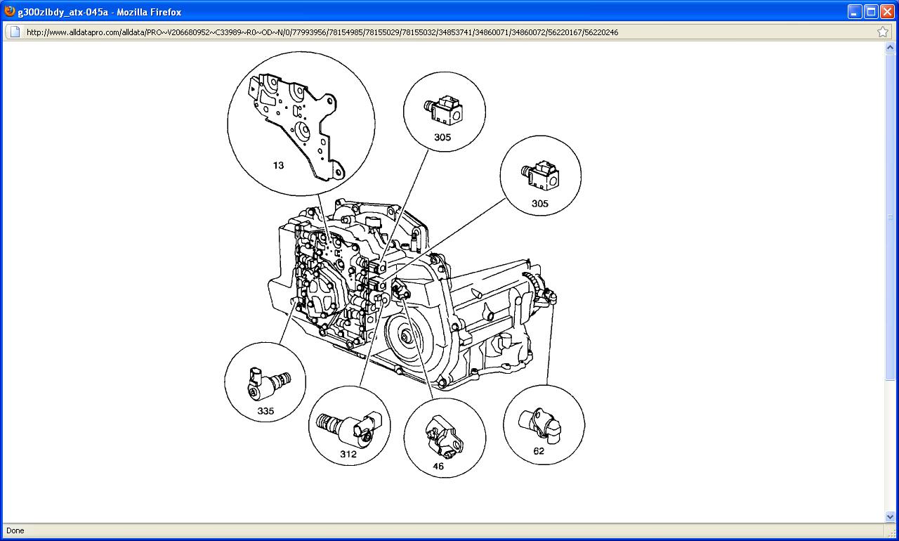
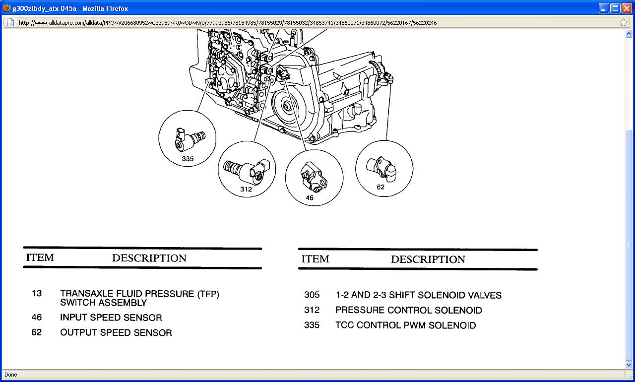
They use that transmission in other cars so there isn't going to be a problem finding part's.They sell the solenoid's at www.rockauto.com and you can find them other place's.I posted diagrams showing you the locations of the solenoids on the valve body.I also posted instructions on how to remove the side cover.


REMOVAL

1. Remove transaxle case side cover.

IMPORTANT: Retainer clips hold in each of the valve line-ups. Use a small screwdriver in order to remove retainer clips. Be careful not to score valve body when removing retainer clips and valves. Before removing valve line-ups, inspect each valve line-up for free travel.

1-2 Shift Solenoid


2. Remove 1-2 shift solenoid retainer clip and 1-2 shift solenoid with O-ring.

2-3 Shift Solenoid


3. Remove 2-3 shift solenoid retainer clip and 2-3 shift solenoid with O-ring.

Pressure Control Solenoid


4. Remove Pressure Control Solenoid (PCS) retainer clip and pressure control solenoid with two O-rings and screen.

TCC Solenoid


5. Remove TCC solenoid retainer clip and TCC solenoid with two O-rings and screen.

INSTALLATION

IMPORTANT: Inspect all O-ring seals for damage prior to installation. Replace any damaged O-ring seals.

TCC Solenoid

1. Install TCC solenoid with O-ring and screen and install TCC solenoid retainer clip.

Pressure Control Solenoid


2. Install Pressure Control Solenoid (PCS) with two O-rings and screen and PCS retainer clip.

2-3 Shift Solenoid


3. Install 2-3 shift solenoid with O-ring and 2-3 shift solenoid retainer clip.

1-2 Shift Solenoid


4. Install 1-2 shift solenoid with O-ring and 1-2 shift solenoid retainer clip.
5. Install transaxle case side cover.
6. Start engine, warm up transaxle, and check for leaks.
7. Check for proper fluid level using "Transaxle Fluid Level Checking Procedure".


Tools Required

* SA105E Engine Support Bar Assembly
* J-43405 Engine Support Fixture Adapter
* J-41102 Axle Seal Protector

REMOVAL


CAUTION: MAKE SURE VEHICLE IS PROPERLY POSITIONED ON HOIST.

1. Position vehicle on hoist.
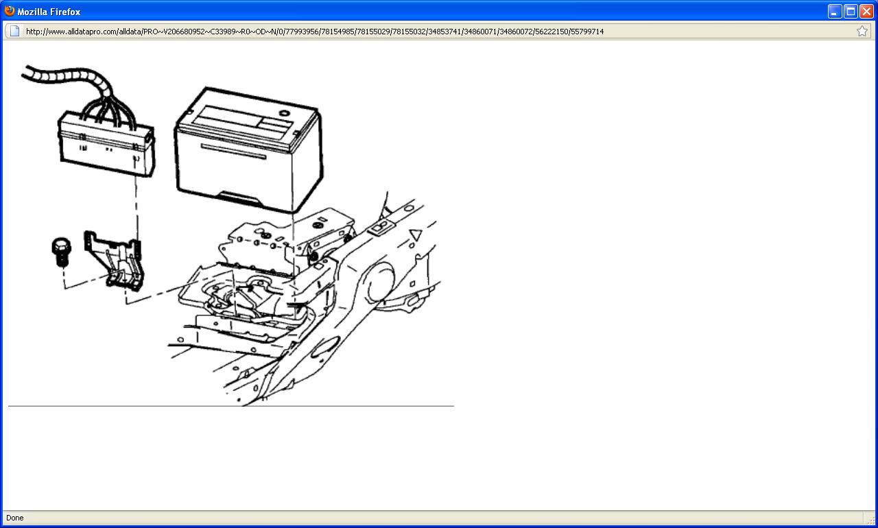
2. Remove battery.

1. Disconnect battery cables (negative first, positive second).
2. Move fan control module. Leave wiring connected, lift module up and away from bracket, and position out of the way.
3. Remove battery hold-down bracket.
4. Remove battery.


3. Disconnect battery feed to underhood fuse block.
4. Disconnect coolant hose from underhood fuse block.
5. Release retaining tabs on underhood fuse block cover and remove.
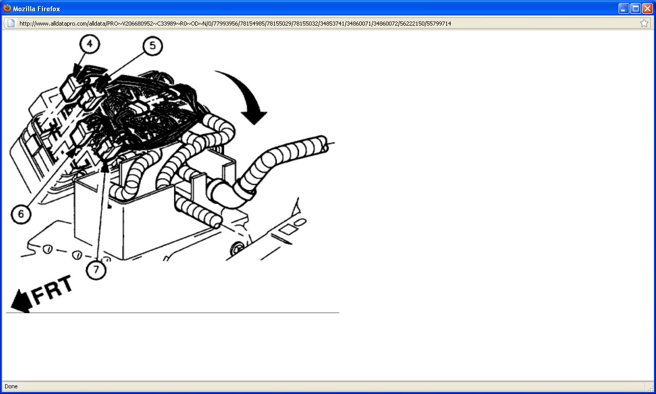
6. Release retaining tabs (2) on underhood fuse block and roll fuse block back (1) to access electrical connectors.


7. Remove following connectors from underhood fuse block: (1) Engine 68-way

(2) Forward Lamp 68-way
(3) I/P 68-way
(4) Forward Lamp 2-way (white)
(5) I/P 2-way (black)
(6) I/P 2-way (green)
(7) I/P 2-way (brown)

8. Lift fuse block off case.

IMPORTANT: There are two tabs that hold the hard shell grommets in place at the bottom of the grommet.
Disengage tabs to remove grommet from case.

9. Remove harnesses from underhood fuse block case by releasing retaining tabs on the bottom of the hard shell grommets.

1. Engine
2. Forward Lamp
3. Instrument Panel (I/P)


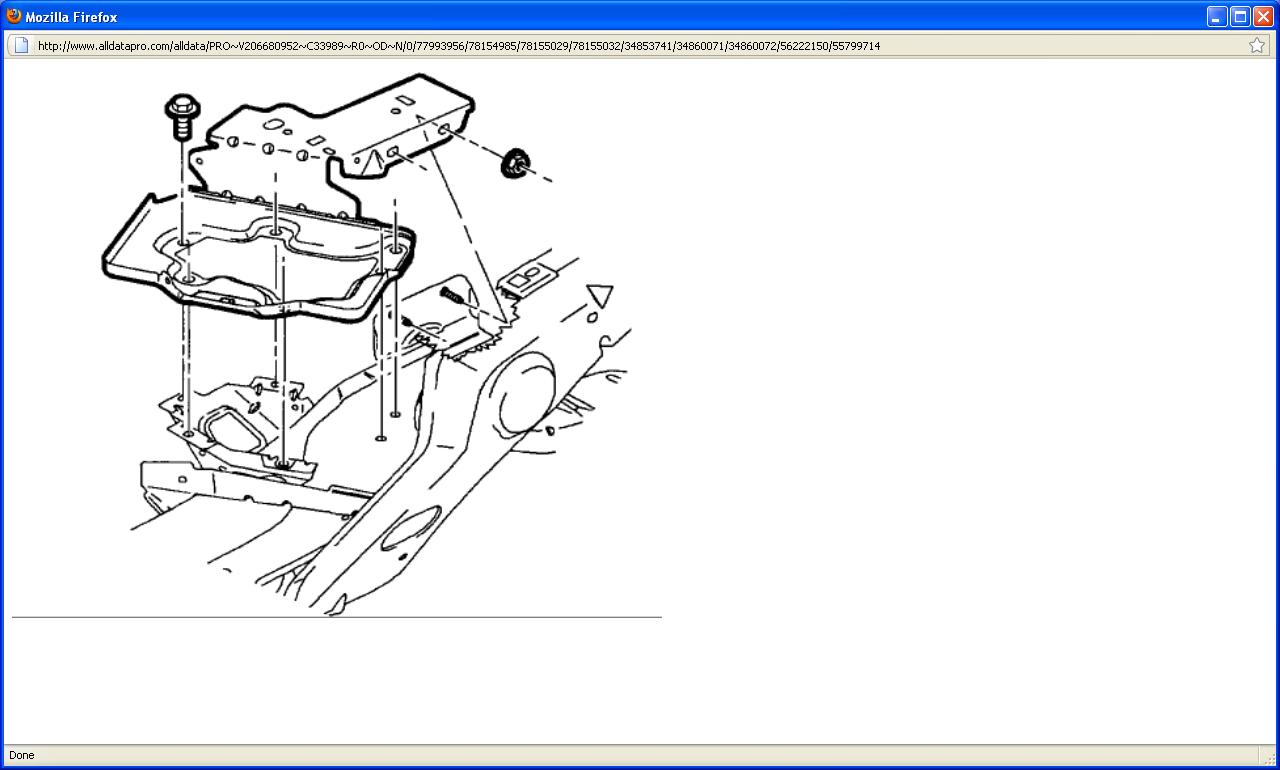
10. Remove underhood fuse block case fastener, and remove case from battery tray.


11. Remove battery tray fasteners and battery tray.
12. Remove wire harness from transaxle case side cover.


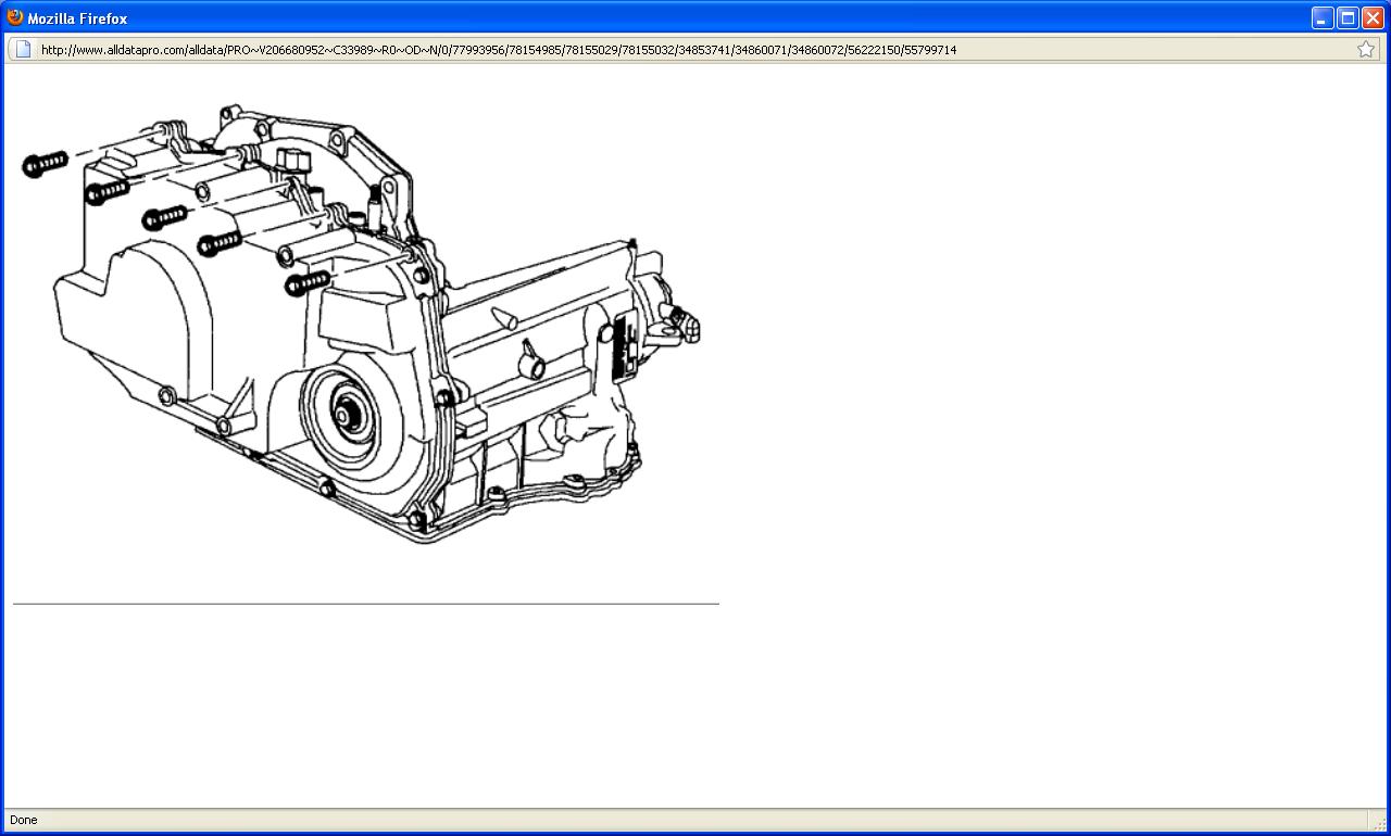
13. Remove upper transaxle case side cover fasteners.


14. Install engine support fixture assembly SA105E with engine support fixture adapter J-43405 as shown. (L4 shown)


15. Install engine support fixture assembly SA105E with engine support fixture adapter J-43405 as shown. (V6 shown)


16. Mark position of and remove left transaxle mount bolts.


17. Remove left transaxle mount from engine compartment rail.
18. Remove frame assembly.


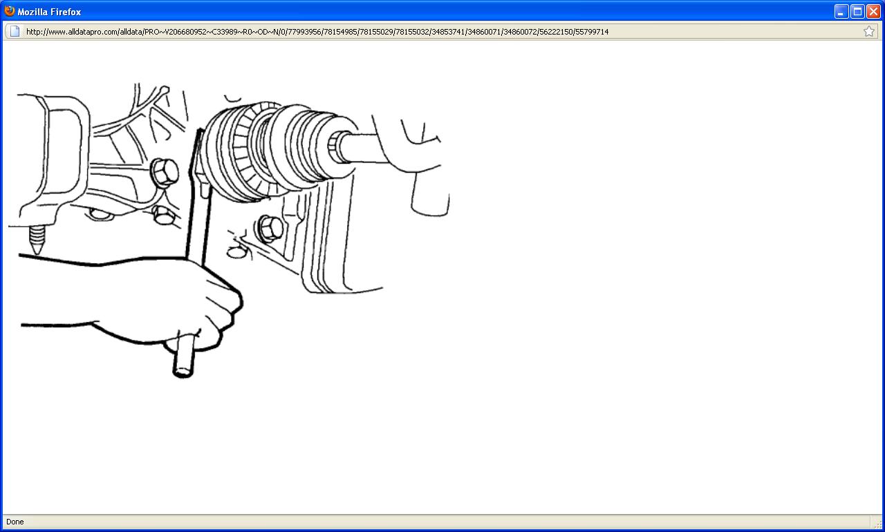
NOTICE: To prevent damage to the CV joint boots, be careful not to allow them to contact other parts during the removal/installation process. Also, never pull on the shaft assembly.

19. Remove left drive axle from transaxle using a pry bar. Remove axle retaining ring from output shaft of transaxle and discard. The axle can be left in the steering knuckle. Tie the axle up and out of the way.


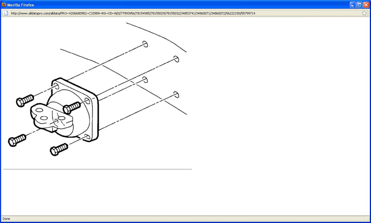
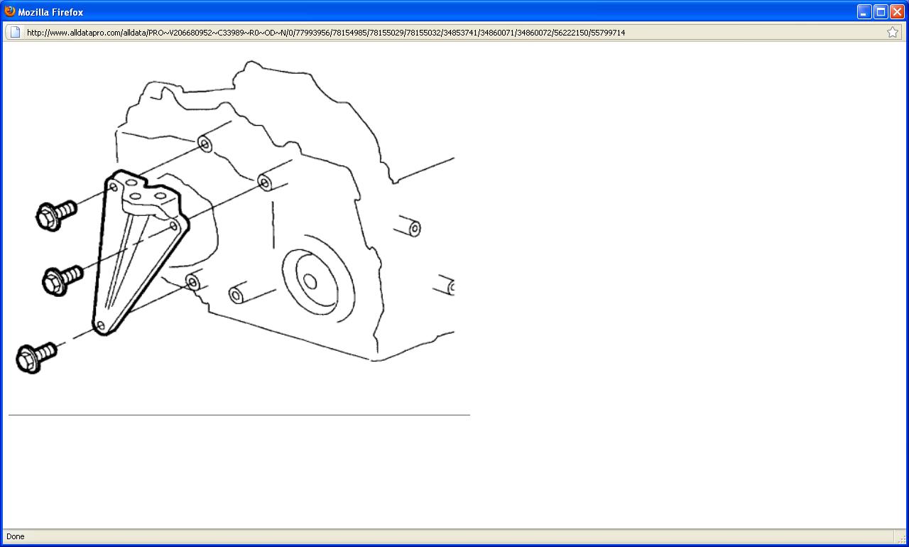
20. Remove power steering lines from left transaxle mount bracket. Remove transaxle mount bracket fasteners and remove bracket.


NOTICE: Pry on side cover near locating dowel pins to prevent damage to sealing surfaces.

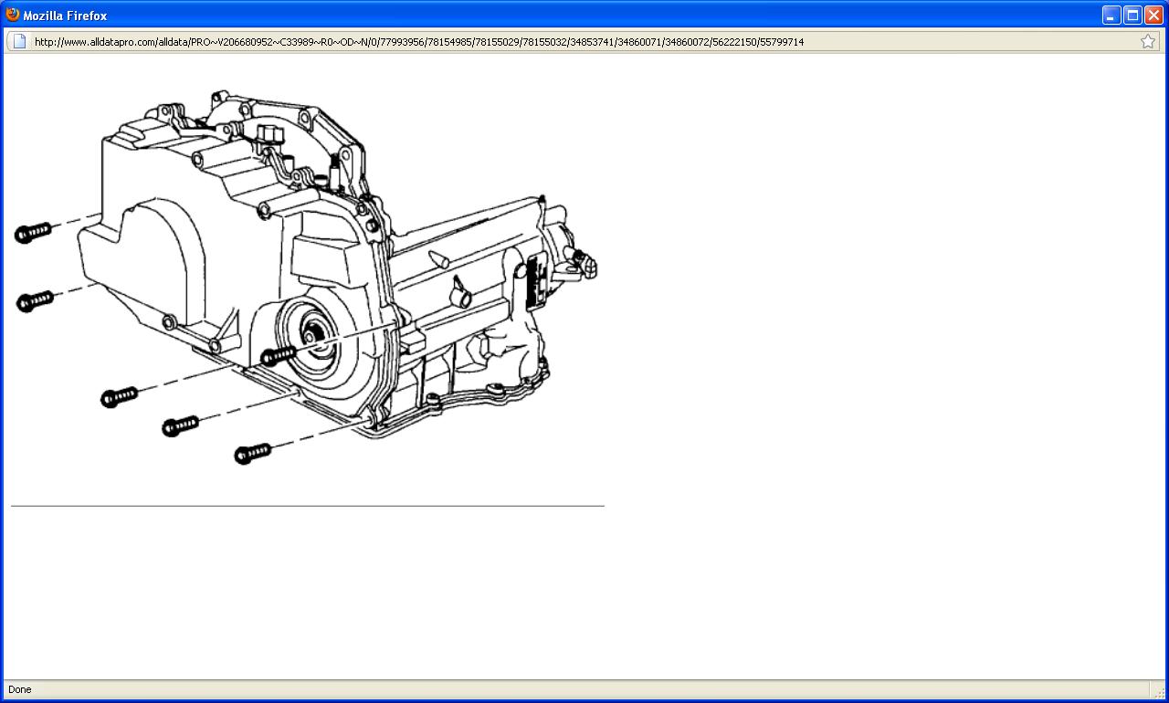
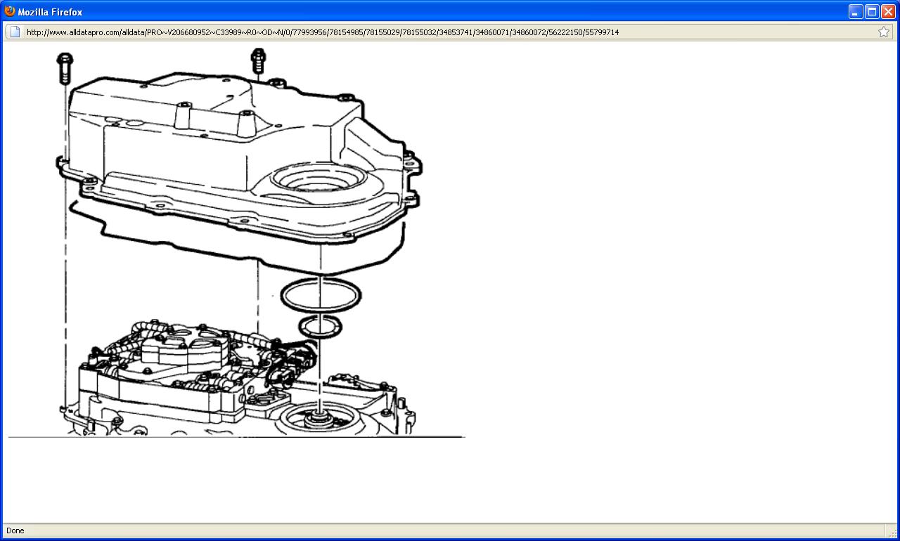
21. Remove remaining transaxle case side cover bolts and remove case side cover.


22. Remove two case side cover gaskets and side cover to driven support thrust washer, if they did not remain with the side cover assembly when it was removed.

INSTALLATION


1. Inspect case side cover for cracks or damage to seal grooves and mounting bosses.
2. Inspect side cover seals for damage. Side cover seals are reusable if not damaged.
3. Thoroughly clean side cover and side cover seals. Clean and dry seal grooves and axle seal bore.
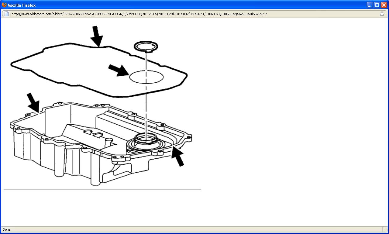
4. Install case side cover gaskets into grooves on side cover. Retain seals with petroleum jelly.
5. Install side cover to driven sprocket thrust washer onto side cover. Retain with petroleum jelly.


NOTICE: Axle seal protector J41102 must be used on the output shaft of the transaxle to protect the axle seal from damage when installing the case side cover. If J41102 is not used, damage to seal may result.

6. Install axle seal protector J41102 on output shaft of transaxle, and install side cover assembly onto transaxle case.
7. Install and hand start lower side cover-to-transaxle case bolts and tighten. Torque: 20 Nm (15 ft. lbs.)


8. Install left transaxle mount bracket to transaxle. Torque: 90 Nm (66 ft. lbs.)
9. Install power steering lines to left transaxle mount bracket. Torque: 10 Nm (89 inch lbs.)

NOTICE: In order to prevent damage to axle shaft splines during vehicle operation, add grease (P/N 7843867) to axle shaft splines prior to axle shaft installation.

10. Install a new axle retaining clip on output shaft of transaxle. Untie left axle shaft and install axle shaft into transaxle.
11. Install frame assembly.
12. Lower vehicle.


13. Install left transaxle mount to engine compartment rail. Torque: 20 Nm (15 ft. lbs.)


NOTICE: If the powertrain mount is not reinstalled in its original position, it could lead to premature mount wear.

14. Reference alignment marks made during disassembly and install left transaxle mount bolts. Torque: 55 Nm (41 ft. lbs.)
15. Remove engine support bar assembly.


16. Install upper transaxle side cover fasteners. Torque: 20 Nm (15 ft. lbs.)
17. Install wire harness to transaxle case side cover. Torque: 20 Nm (15 ft. lbs.)


18. Install battery tray and battery tray fasteners. Torque: 15 Nm (11 ft. lbs.)


19. Install underhood fuse block case to battery tray and install bolt. Torque: 9 Nm (80 inch lbs.)
20. Install wire harnesses to fuse block case. The wire harness grommets have retaining tabs that lock into the case (3) when the harnesses are fully installed.
21. Snap fuse block onto fuse block case hinges.


22. Install following connectors to underhood fuse block: (1) Engine 68-way

(2) Forward Lamp 68-way
(3) I/P 68-way
(4) Forward Lamp 2-way (white)
(5) I/P 2-way (black)
(6) I/P 2-way (green)
(7) I/P 2-way (brown)


23. Secure underhood fuse block to fuse block case by rotating down and snapping into place.
24. Install underhood fuse block cover.
25. Secure coolant hose into place on fuse block cover.
26. Install battery feed cable to underhood fuse block. Torque: 16 Nm (12 ft. lbs.)


27. Install battery.

1. Install battery into battery tray.
2. Install battery hold-down bracket. Torque: 20 Nm (15 ft. lbs.)
3. Install fan control module by sliding down onto battery hold-down bracket.

CAUTION: POSITIVE BATTERY TERMINAL MUST BE CONNECTED FIRST TO PREVENT ARCHING.

4. Install battery cables (positive first, negative second). Torque: 17 Nm (13 ft. lbs.)

28. Start engine, warm up transaxle and check for fluid leaks.
29. Check for proper fluid level.
Mar 6, 2011 at 4:48 AM
Avatar
LALFAN
  • MEMBER
  • 179 POSTS
i put on junk yard parts and so far having good luck. put on switch on top of trans and no more code. also had a problem with mass air flow, so i changed it and no more code. blanked it out sunday and have been driving it since with no codes. it seems like it wants to hesitate to shift into od but if i let up on the gas a little it shifts right away. is their any additives that i would want to try before i change the filter or after i change it. or just put in whatever fluid it calls for. thanks for your help.
Mar 12, 2011 at 1:26 AM
Avatar
SATURNTECH9
  • CERTIFIED EXPERT
  • 30,869 POSTS
You change the transmission fluid every 50,000 mile's don't use any additive's.Also your not getting that code P0742 anymore?As far as having to let up on the gas for it to shift that is usually a plugged cat.When it's doing that you need to have a exhaust back pressure test done.Use DEXRON III or Equivalent also it take's 6.9 qts with change the fluid and the filter.Also look for debris like metal which will be shinny.
Mar 12, 2011 at 4:32 AM
Avatar
LALFAN
  • MEMBER
  • 179 POSTS
i went to freeway muffler and he could only check the back one. it was fine. said it had three couldnt get to the other two. said it didnt feel like they are plugged. had to drill a hole and use a probe. they have a way of power flushing the trans. $169 with fluid and filter. is that a good thing or bad. it flushes through a coolant line. put in gas again, not really doing good. 22 mpg but that is some in town driving to. thanks
Mar 14, 2011 at 10:51 PM
Avatar
SATURNTECH9
  • CERTIFIED EXPERT
  • 30,869 POSTS
He had to drill a hole to test the back pressure?That's crazy they make adapter's and all you do is unscrew the o2 sensor in the exhaust manifold screw the adapter in hook up the gauge and see the back pressure.You can do that to both manifold's that way you can check the back pressure on each bank by itself.Also do it when's hot and you have to let up on the gas for it to shift.As far as transmission flushes go on that car i would not do it bad thing to do.We used to do those at the saturn dealer i worked at and we had car's come back because debris's were pushed into the shift solenoid's and plugged them up.
Mar 15, 2011 at 12:17 AM
Avatar
LALFAN
  • MEMBER
  • 179 POSTS
i will check on a screw in tester. and i wont power flush. thanks
Mar 15, 2011 at 1:02 AM
Avatar
SATURNTECH9
  • CERTIFIED EXPERT
  • 30,869 POSTS
Your welcome the testers are only like 30-40 let me know what you find.
Mar 15, 2011 at 2:18 AM
Avatar
LALFAN
  • MEMBER
  • 179 POSTS
changed the filter and fluid. was not able to take off side cover at this time, but did crack the bootom lose to let smoe fluid run out. hoped it would help flush anything out along the side. then dropped the pan. it did have fine metal dust in it. nothing big. cleaned everything up and tried to straighten pan alittle. it had been bottomed out in the front. haveing problems with it sealing up with cheap gasket. ordered a saturn one today. $60 if its like the one that was in it, it should work. then i can try it. i also have a 00 ls1 with a 5 speed. it has a left axle leak that this shop cant get stopped leaking. how much movement should the axle have up and down going into the housing where the bearing is in the inside. it seams to move alot. they say these bearings usally dont go bad. needs to be fixed. thanks
Mar 21, 2011 at 10:12 PM
Avatar
SATURNTECH9
  • CERTIFIED EXPERT
  • 30,869 POSTS
Did you ask about that seal leak on here recently because if you did i worked with you on that question.Let me know so i can answer that question.Also they have back pressure tester's that screw in where the o2 sensor's are there pretty cheap i think there like 40 something.
Mar 21, 2011 at 10:25 PM
Avatar
LALFAN
  • MEMBER
  • 179 POSTS
yes this is the same axle leak. i can move that shaft up and down a lot it seems right where it goes into the seal. oreillys wants $60 for a screw in tester. one of the guys that works there says he has one and would do it for 20.
Mar 22, 2011 at 12:09 AM
Avatar
SATURNTECH9
  • CERTIFIED EXPERT
  • 30,869 POSTS
Here's a back pressure tester check it out http://www.amazon.com/Tool-Aid-33600-Exhaust-Pressure/dp/B0002SQW9S/ref=sr_1_1?ie=UTF8&s=automotive&qid=1300753341&sr=1-1.If you get a tester i can give you the instructions on how to test it.As far as your axle seal leaking there is only a few things it could be the axle seal itself the axle or the axle moving around too much.I have only seen a few leak and it's always just been the seal.You said something about they changed the axle did they change the axle because of the leak or after the new seal leaked?
Mar 22, 2011 at 12:29 AM
Avatar
LALFAN
  • MEMBER
  • 179 POSTS
they put in a new seal first. then it leaked again so they changed both . then they changed the seal again. now its leaking again. it seams to have alot of movement in it. this is the forth time.
Mar 22, 2011 at 1:10 AM
Avatar
SATURNTECH9
  • CERTIFIED EXPERT
  • 30,869 POSTS
Like i said there is the seal the axle the case and the bearing that can cause excessive movement that can cause a leak.I would put some leak dye in the transmission and follow the leak back to it's source.
Mar 22, 2011 at 7:11 PM
Avatar
LALFAN
  • MEMBER
  • 179 POSTS
i will have to ask them about this. they say they can see it come from between the seal and shaft. if so, will i need to replace the bearing inside and how much work and money does this usally run. i dont think they could ruin that many seals. they been in buisness a long time and ive had good luck with them.
Mar 22, 2011 at 10:34 PM
Avatar
SATURNTECH9
  • CERTIFIED EXPERT
  • 30,869 POSTS
They should be able to figure it if they are that good and have been in business that long.They should be able to pull the seal and see if there is a lot of play where the axle goes in.To replace the bearing it's a lot of work and labor.Might be cheap to just find a used transmission if that's the case.
Mar 22, 2011 at 11:07 PM
Avatar
LALFAN
  • MEMBER
  • 179 POSTS
do you know what years and models of cars the transmissions will interchange withmine? just in case i have to get to that point. i really think it is to sloppy to seal up. then i will have to price fixing or changeing it out. thanks
Mar 23, 2011 at 9:13 PM
Avatar
SATURNTECH9
  • CERTIFIED EXPERT
  • 30,869 POSTS
Let me know if it get's down to replacing or fixing and we will go from there.I would have to search thru all the year's and match part number's etc.Which i don't mind doing for you i just don't want to have to do it for no reason.I could spend that time helping other user's with there car's.So keep me posted on what you find and i will be more then happy to help you out with that.
Mar 23, 2011 at 9:44 PM
Avatar
LALFAN
  • MEMBER
  • 179 POSTS
drove the ls2 today. seems to shift smoother than before. the rpm's going down the road seem to be less than before. went to omaha and back and only got 24 mpg. the service engine light came on again. p0421 andp0431. warm up catalyst efficiency below threshold bank 1 and 2. i guess more problems. my scanner does not give me misfires per cyl. on this car but the 99 sl1 i have it does. dont under stand why it does that. thanks
Mar 27, 2011 at 10:50 PM
Avatar
SATURNTECH9
  • CERTIFIED EXPERT
  • 30,869 POSTS
Are you sure you don't have a P0422 and a p0432?I can't find the one's you listed.Let me know.
Mar 27, 2011 at 11:04 PM
Avatar
LALFAN
  • MEMBER
  • 179 POSTS
that is what it says. they are in my chilton l series manual. and i did order a back pressure tester. should get it this week. thanks
Mar 27, 2011 at 11:38 PM
Avatar
SATURNTECH9
  • CERTIFIED EXPERT
  • 30,869 POSTS
I can't find the ones you posted but the code's P0422 and p0432 is the same code description warm up catalyst efficiency below threshold bank 1 and 2 i posted the code descriptions and the trouble tree's for you the first two posted ones is the code P0422 and the number 3 and 4 images is the code P0432.Let me know what you find.


The catalyst is a device used to control emission content. Although the catalyst is active as soon as exhaust gas is passed through it, this diagnostic will not run until the front and rear oxygen sensors are both in open loop. The oxygen storing capability of the catalyst is monitored by viewing the rear oxygen sensor's response to an oscillating air-fuel ratio. The ECM computes how a near-failure catalyst would cause a rear oxygen sensor to react to an oscillating air-fuel ratio. These values are compared with the actual rear oxygen sensor response. If the actual response deviates a calibrated amount from the computed values, this code will set.

DTC PARAMETERS
DTC P0422 will set when:

* Closed loop is enabled
* Engine Speed is between 1400 and 2200 rpm
* Catalyst temperature greater than 380°C (716°F)
* No front or rear, misfire, MAF, TP, purge solenoids codes set

DTC P0422 a (type B) DTC.

DIAGNOSTIC AIDS
Once set, this code should remain active. Under certain driving conditions the catalyst monitor test may pass. This condition may occur if driving the vehicle at highway speeds (high air flow) but if this code is set, and there are no exhaust leaks, the converter should be replaced. If a misfire code is detected, the catalyst monitor test will not run. Be sure to correct a misfire condition before replacing the converter.

Possible causes:

* Exhaust system leaks between front and rear sensors, or rear sensor leaking.
* Catalyst deteriorated due to excessive time operating vehicle with a catalyst damaging misfire.
* Contamination of converter due to incorrect sealant, fuel, or fuel additive.


The catalyst is a device used to control emission content. Although the catalyst is active as soon as exhaust gas is passed through it, this diagnostic will not run until the front and rear oxygen sensors are both in open loop. The oxygen storing capability of the catalyst is monitored by viewing the rear oxygen sensor's response to an oscillating air-fuel ratio. The ECM computes how a near-failure catalyst would cause a rear oxygen sensor to react to an oscillating air-fuel ratio. These values are compared with the actual rear oxygen sensor response. If the actual response deviates a calibrated amount from the computed values, this code will set.

DTC PARAMETERS
DTC P0432 will set when:

* Closed loop is enabled
* Engine Speed is between 1400 and 2200 rpm
* Catalyst temperature greater than 380°C (716°F)
* No front or rear, misfire, MAF, TP, purge solenoids codes set

DTC P0432 a (type B) DTC.

DIAGNOSTIC AIDS
Once set, this code should remain active. Under certain driving conditions the catalyst monitor test may pass. This condition may occur if driving the vehicle at highway speeds (high air flow) but if this code is set, and there are no exhaust leaks, the converter should be replaced. If a misfire code is detected, the catalyst monitor test will not run. Be sure to correct a misfire condition before replacing the converter.

Possible causes:

* Exhaust system leaks between front and rear sensors, or rear sensor leaking.
* Catalyst deteriorated due to excessive time operating vehicle with a catalyst damaging misfire.
* Contamination of converter due to incorrect sealant, fuel, or fuel additive.
Mar 27, 2011 at 11:57 PM
Avatar
LALFAN
  • MEMBER
  • 179 POSTS
so what is the pre-converter. suppose i need to check the hole they put in the exhaust to check the back pressure at freeway muffler. why would my scanner not show misfires on the ls2 but wil show them on the 99 sli. ita auto x-ray 6000. on the front down pipe on the exhaust thereis a small rounded piece in the pipe, just down from the manifoldi dont no what it is or does. is there anything else on my scanner to look for in the run data. thanks i think i owe you more money.
Mar 28, 2011 at 12:32 AM
Avatar
SATURNTECH9
  • CERTIFIED EXPERT
  • 30,869 POSTS
The pre converter is that part right below the exhaust manifold that is attached to the exhaust manifold.I can't tell you why your 1999 SL1 shows miss fires per cylinder and your 2000 LS2 doesn't.So does your 2000 LS2 miss firing or have miss fire code's?I would follow the trouble tree's i posted there pretty straight forward they really don't have any scanner data to watch or look at.They just ask if you have a exhaust leak a miss fire etc.If you want to donate more feel free too.
Mar 28, 2011 at 12:47 AM
Avatar
LALFAN
  • MEMBER
  • 179 POSTS
we had a different scanner on it before and it showed misfires on 2 different cylinders. plugs were good and tried different coil packs and it didnt change anything. i had it in the shop for that and it didnt help. same shop as the leaky seal. no codes for that. may be i can him to try his scanner again. how do you donate more money? thanks
Mar 28, 2011 at 12:57 AM
Avatar
SATURNTECH9
  • CERTIFIED EXPERT
  • 30,869 POSTS
Was it setting a code for the miss fire's?What cylinder's were miss firing?Are there still miss fire's?Does your engine burn oil?If so how much?I will find out how you can donate more money they change the whole site recently i'm still getting use to it.
Mar 28, 2011 at 1:02 AM
Avatar
LALFAN
  • MEMBER
  • 179 POSTS
no codes for the missfires. will try to find out what cyl. dont seem to be burning oil. dont smoke
Mar 28, 2011 at 1:28 AM
Avatar
SATURNTECH9
  • CERTIFIED EXPERT
  • 30,869 POSTS
you said there is no miss fire code's but is there miss fire's?Because it says to fix that before addressing the code's.If you have oil burning that can make cats go bad.Kinda funny how you have code's for both pre cats at the same time.
Mar 28, 2011 at 1:30 AM
Avatar
SATURNTECH9
  • CERTIFIED EXPERT
  • 30,869 POSTS
Here is the answer i got for making another donation.

you can have him post another question that is just a thank you and choose to donate there. They can send it directly thru paypal using [email protected]
Mar 28, 2011 at 3:33 PM
Avatar
LALFAN
  • MEMBER
  • 179 POSTS
ok sounds good. you have given me alot of infoand i probably need more. you will be sick of this when we get done. the light went out when i started the car to come home from work today. its 12 miles home and it stayed out. so not sure what its doing. thanks for all the info.
Mar 28, 2011 at 9:24 PM
Avatar
SATURNTECH9
  • CERTIFIED EXPERT
  • 30,869 POSTS
Alright keep me posted on what you find.
Mar 29, 2011 at 6:53 AM