altnator not chargeing bit checked ok.

2000 DODGE NEON
140,000 MILES • 4 CYL • 2WD • MANUAL
Avatar
CREAPN4LIFE
  • MEMBER
  • 36 POSTS
How do i bypass ecm voltage regilator in 2000 dodge neon? Im not sure where field wire from after market voltage regulator goes on factory voltage reg.. and if i have to cut factory voltage reg wire to kill circuit so i dont fry the ecm? Please help befor i blow my car up. I love this car and only have had for couple months. Note this started after my alt belt broke.
Jan 28, 2011 at 4:08 AM
Advertisement
Avatar
CREAPN4LIFE
  • MEMBER
  • 36 POSTS
I also have ran a obdll scan on it and its comeing back with the fallowing codes.p0118,p1594,p0622,p0108,p0123,p0132, & all of these codes at the bottom say high input or system tovhigh.. replaced map sensor,coolant temp sensor,ambiant temp sensor put new batt connectors,,, + new ground wires.. fixed any bare wires.. alt + batt checked out ok off the car but today had checked on car and alt not putting out any charge.. i just want 2 bypass ecm voltage regulator tell i can afford to get new ecm.. please help would be most greatfull.
Jan 28, 2011 at 4:23 AM
Avatar
CARADIODOC
  • CERTIFIED EXPERT
  • 34,306 POSTS
The voltage regulator inside the Engine Computer gives extremely little trouble. I can help you install a 1970s regulator but first, measure the voltages on the three alternator wires. The fat output wire must have 12 volts all the time. One small wire will have 12 volts and the other small wire must have less than that but not 0 volts. Those last two voltages will only be there when the engine is running, not just with the ignition switch turned on. Holler back with those readings.

caradiodoc
Jan 28, 2011 at 6:04 AM
Advertisement
Avatar
CREAPN4LIFE
  • MEMBER
  • 36 POSTS
K i was able 2 test the wires on alt and fat wire was a lil under 12 volts and one of the lil wires was like 14 vlots and this is when batt at 100% charged and car running.. whats up with
that??
Jan 31, 2011 at 11:27 PM
Avatar
CARADIODOC
  • CERTIFIED EXPERT
  • 34,306 POSTS
Not sure how you got higher voltage on the small field wire than what was on the output wire, but the secret is the voltage on the second small wire. It's going to be the same as the first small wire, less than that, or 0 volts. My bet is for 0 volts. That would mean the brushes are worn. If you find between around 4 - 11 volts, that circuit is working. In that case, suspect a shorted diode in the alternator.

caradiodoc
Jan 31, 2011 at 11:50 PM
Avatar
CREAPN4LIFE
  • MEMBER
  • 36 POSTS
K well ill check it agian and ill have alt checked agian.. i checked it in a rush cause its like -20 below zero out. Soo ill let ya know when i check it agian..

Feb 1, 2011 at 1:05 AM
Avatar
CREAPN4LIFE
  • MEMBER
  • 36 POSTS
Do u think charging system could cause sensor codes 2 throw
Feb 1, 2011 at 9:55 PM
Avatar
CREAPN4LIFE
  • MEMBER
  • 36 POSTS
Checked both lil wires both are reading high like jumping between 12 and 14.5 volts fat wire reading 11.5 volts.. whats with that is it my alt or ecu???
Feb 1, 2011 at 10:55 PM
Avatar
CARADIODOC
  • CERTIFIED EXPERT
  • 34,306 POSTS
Yup. System voltage that is too low can affect sensor readings, however, there is a set of conditions for a code to set. One of those conditions is that other certain codes can't already be in memory. As an example, you can get a high manifold vacuum reading from the MAP sensor by snapping the throttle while you're standing beside the car. The only way to get a high manifold vacuum reading for seven seconds or longer is if you're coasting with your foot off the gas. That's how the computer knows the car is moving. No pulses from the vehicle speed sensor is a legitimate condition when the car is standing still, but if the computer knows the car is moving, there had better be a signal coming from the speed sensor. If not, it will set a code. If there is already a fault code set in memory for the MAP sensor, there is no way to know what to expect from the speed sensor, so no code can be set for him.

Some codes will not set below a certain temperature, or unless the problem acts up for a required period of time. In the case of the alternator, the code will be "field circuit not switching properly".

Any code for something that could have an adverse effect on tail pipe emissions will turn on the Check Engine light. That includes charging system codes, but not because it will affect sensor readings. It's because low voltage to the injectors or ignition coil(s) could cause misfires and raw, unburned fuel in the exhaust. So the charging system won't CAUSE sensor codes to set but it could result in other codes being set.

caradiodoc
Feb 1, 2011 at 11:17 PM
Avatar
CARADIODOC
  • CERTIFIED EXPERT
  • 34,306 POSTS
It suggests the field circuit is ok. What I think is happening is the circuit is switching on and off about 400 times per second. The percentage of on-time varies to vary average current flow through the field circuit. That's the way vcr power supplies work. Digital voltmeters take a reading, analyze it, then display the reading while taking the next measurement. Subsequent readings might be taken while the field circuit is turned off or turned on. This all happens multiple times per second and is why the display jumps around.

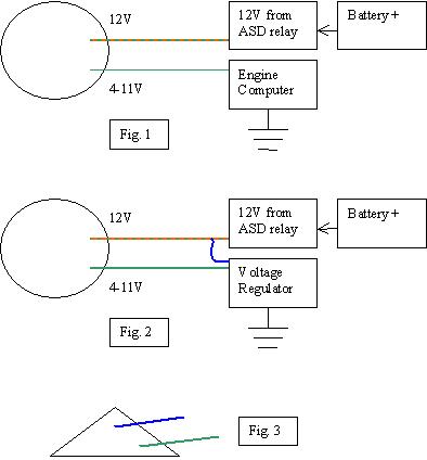
What we need to do is to perform a "full-field" test to bypass the voltage regulator. That involves grounding the dark green wire between the alternator and the voltage regulator in the Engine Computer. The best way to do that, if you can get to it, is to ground that wire at the back of the alternator while the engine is running, and measure the voltage on the output wire. That dark green wire can also be grounded at the Engine Computer but I don't know how hard that will be to access the connectors so you can back-probe it. It's in pin 8. The trouble is both connectors are black, but there is no pin 8 in the wrong connector. Each one has four rows of pins with ten pins in each row. Pin 8 is in one of the outer rows, third from the end. Just be sure it's a dark green wire.

If the two wires are plugged into the back of the alternator, it will be safer to ground the dark green wire there. The wrong wire is dark green with an orange stripe. On some models those two wires go through a small black plastic block so you can't tell which wire goes to which terminal. If that's the case, I can paste a copy of a procedure that might help identify the right terminal.

When you ground that wire, watch the voltmeter or the brightness of the head lights. You'll hear the alternator strain. If the voltage doesn't go up significantly, suspect a shorted diode in the alternator.

caradiodoc
Feb 2, 2011 at 1:01 AM
Avatar
CREAPN4LIFE
  • MEMBER
  • 36 POSTS
K i just did a full field test and when i ground the dark green wire on back of alt it made the volts go even higher but i also checked both wires with meter and they both were just jumping in the 12 volt range what do i do now?
Feb 2, 2011 at 3:35 AM
Avatar
CREAPN4LIFE
  • MEMBER
  • 36 POSTS
Green wire with orange stripe is reading about 12.1 volts and the solid green wire is readinding betwen 11.7 & 11.9 volts.
Feb 2, 2011 at 3:42 AM
Avatar
CARADIODOC
  • CERTIFIED EXPERT
  • 34,306 POSTS
What was the voltage on the fat output wire during the full-field test? It should have gone up to at least 16 volts.

caradiodoc
Feb 2, 2011 at 3:43 AM
Avatar
CREAPN4LIFE
  • MEMBER
  • 36 POSTS
Ya it was jumping around 15 and 15.9 and it did jump a few times to 16.. and dont know if it matters but throuugh all of this i have 2 keep vacum line that runs into pvc that runs into valve cover is un hooked cause when its hooked up it wants to kill my motor.
Feb 2, 2011 at 4:07 AM
Avatar
CARADIODOC
  • CERTIFIED EXPERT
  • 34,306 POSTS
Boy, that sure would seem like the regulator is defective. Darn the bad luck! The last thing is to find that dark green wire in the connector for the Engine Computer. I never had one apart, but I'm guessing there is a plastic cover that can be snapped off so you can back-probe the terminals while they're still connected to the computer.

Stick a stretched out paper clip in next to that wire so you can measure the voltage on it. If you find 0 volts, that wire is broken somewhere between that plug and the alternator. If there is some voltage there, you can use a jumper wire to ground that terminal and it should also cause the system to full-field. If that works, I guess I'd have to agree the regulator circuit is the problem.

If the battery was recently disconnected, that would explain the low idle speed. There's an easy fix later once the charging system is working. It just involves driving it.

caradiodoc
Feb 2, 2011 at 4:21 AM
Avatar
CREAPN4LIFE
  • MEMBER
  • 36 POSTS
K well with car not running it reads 4 volts for some reason it wont start now but i think i might be out of gas..lol.
Feb 2, 2011 at 4:51 AM
Avatar
CARADIODOC
  • CERTIFIED EXPERT
  • 34,306 POSTS
That 4 volts must be coming out of the computer. It can show up from the internal circuitry. If you measure that same voltage at the alternator, the wire must be ok.

caradiodoc
Feb 2, 2011 at 5:31 AM
Avatar
CREAPN4LIFE
  • MEMBER
  • 36 POSTS
K got gas its running. Checked while running solid green whire only,putting out 2.5 volts... And i ground that solid green wire right at the compuer and it reads o... What do i do know??
Feb 2, 2011 at 5:44 AM
Avatar
CARADIODOC
  • CERTIFIED EXPERT
  • 34,306 POSTS
What reads 0? Where are you measuring?

caradiodoc
Feb 2, 2011 at 5:51 AM
Avatar
CREAPN4LIFE
  • MEMBER
  • 36 POSTS
Wire comeing out of computer..how do i wire this after market voltage regulater???
Feb 2, 2011 at 6:00 AM
Avatar
CARADIODOC
  • CERTIFIED EXPERT
  • 34,306 POSTS
Hope this diagram comes out ok. Figure 1 is what you have now. Current flows from the battery, through the automatic shutdown relay, (when the engine is running), through the rotating field winding, through the voltage regulator inside the Engine Computer, to ground and back to the battery.

In Figure 2, the external regulator takes the place of the circuit in the Engine Computer. The blue wire must be added from the green / orange feed wire to the blue wire in the regulator's connector. That is the power wire to run the regulator and it's the system voltage sensing wire. That wire exists in your current system too.

Figure 3 shows what the wire end of the 1970s regulator connector looks like. The blue wire in the middle connects to the green / orange wire. Cut the green wire from the computer's connector and connect it to the green wire in the regulator's connector. The new regulator must be bolted to the body sheet metal because the metal housing is the third connection.

caradiodoc
Feb 2, 2011 at 7:11 AM
Avatar
CREAPN4LIFE
  • MEMBER
  • 36 POSTS
Ok so do i cut the solid green wire at the computer & run that wire to the field wire on the new voltage regulator? Then cut the green/orange wire and run that to the 12volt switch wire on new voltage regulator?? Sorry the voltage regulator i got dont have the connector i had to make one.. if th is not correct could u just explan it useing term field wire and the switch wire please. Im kind of a dumb **** when it comes to **** like this..
Feb 2, 2011 at 8:47 AM
Avatar
CARADIODOC
  • CERTIFIED EXPERT
  • 34,306 POSTS
Don't cut the green / orange wire. Just splice into it and connect it to the center terminal on the new regulator. This diagram might help. The green / orange wire on top is original on your car. Splice into it and run that wire to the center terminal for the regulator. That's the blue wire in my drawing. (I used blue because everything dark blue under the hood in the '70s had 12 volts when the ignition switch was on. That's the color you'll find if you grab a regulator connector from the salvage yard).

The green wire is cut anywhere between the alternator and computer. The end still hooked to the alternator goes to the regulator terminal in the corner of the connector.

caradiodoc
Feb 2, 2011 at 9:23 AM
Avatar
CREAPN4LIFE
  • MEMBER
  • 36 POSTS
Ok that makes much better sence ill let ya know when i get it done and how thingss work.. thanks much for all the help. This site has been the best ever.. if this dont work i think im just gonna have to blow my car up.. if ya f
Feb 2, 2011 at 1:37 PM
Avatar
CREAPN4LIFE
  • MEMBER
  • 36 POSTS
K done system is chargeing but not seem to be running right and now it wont start what now??
Feb 2, 2011 at 9:13 PM
Avatar
CARADIODOC
  • CERTIFIED EXPERT
  • 34,306 POSTS
Hold the gas pedal down 1/8 inch. If it starts but won't stay running with your foot off the gas, the Engine Computer must relearn "minimum throttle". To meet the conditions for that to take place, drive it at highway speed with the engine warmed up, then coast for at least seven seconds without touching the brake or gas pedals.

caradiodoc
Feb 2, 2011 at 9:30 PM
Avatar
CREAPN4LIFE
  • MEMBER
  • 36 POSTS
K well thanks for all ur help but car still not running right so im giveing up and i broke down and i just ordered a used ecm for 90 bucks.. should be here tuesday of next week.. so will see if that does the trick.
Feb 3, 2011 at 12:30 AM
Avatar
CREAPN4LIFE
  • MEMBER
  • 36 POSTS
K i just put my new used ecu and car started but then died right away. Did this 3 times but now it wont even turn over & there is a lil red light that comes on???
Feb 8, 2011 at 4:23 AM
Avatar
CARADIODOC
  • CERTIFIED EXPERT
  • 34,306 POSTS
A four-digit security code has to be entered with the Chrysler DRB3 scanner. I think you can get the code from the dealer. That code is already programmed into the SKIM anti-theft module. The vehicle mileage has to be entered too.

caradiodoc
Feb 8, 2011 at 5:21 AM
Avatar
CREAPN4LIFE
  • MEMBER
  • 36 POSTS
Is that a special scan tool? That would require me to have the dealer do?and as far as the milage being entered is that the miliage thats on my car??Is that av
Feb 8, 2011 at 6:04 AM
Avatar
CARADIODOC
  • CERTIFIED EXPERT
  • 34,306 POSTS
Yup. Mileage on the car. That isn't critical, but even after fault codes are erased, there is some information that is stored permanently in the computer and only Chrysler can retrieve it. That will let them see when various fault codes set.

Yes to the scanner. That's the DRB3. Some independent shops have them too. I have one but I've never used to to enter the number. I think the dealer has to get that number.

caradiodoc
Feb 8, 2011 at 6:34 AM
Avatar
CREAPN4LIFE
  • MEMBER
  • 36 POSTS
well last i was here i had just bypassed the ecu voltage regulator. Why indeed that did fix one of my main problems and system is chargeing now, but now that system is chargeing one of the exsiting problems is still there which is the ecu is still telling the sensors there at high circut.. So there for my car still runs like **** its sucking gas like a v10 floods back smoke out tail pipes. The rev limiter kicks in, it sputters. All the same problems other than system is charging. How the hell can i fix this problem and get the ecu to tell sensors what there sapose to in order to run right.
Mar 11, 2011 at 2:10 AM
Avatar
CARADIODOC
  • CERTIFIED EXPERT
  • 34,306 POSTS
I think you have that backwards. The computer takes in the sensor readings then determines how long to hold the injectors open to spray in the calculated amount of fuel. If there is a sensor problem, the computer should detect it, set a fault code, and turn on the Check Engine light. A sensor can still stay within the acceptable range but send the wrong value. The biggest offender of that is the MAP sensor and it has the biggest say in how much fuel is delivered. Try unplugging the MAP sensor while the engine is running. If it runs better, suspect that sensor. Next, check fuel pressure. That is not monitored by the computer. If the pressure is too high, too much fuel will be forced in each time the injector opens. Don't overlook a jumped timing belt. That should cause the Check Engine light to turn on but it's still not something to overlook. Finally, you can use a scanner to view live sensor data while the engine is running. That will let you see what the computer is seeing and how it is responding.
Mar 11, 2011 at 3:18 AM
Avatar
CREAPN4LIFE
  • MEMBER
  • 36 POSTS
ok well i have already checked fuel pressure and it checks out ok.But as far as the timeing belt goes that i think very well could be. Back when this all started was i was parked eating my food with car running cause it was like -15 below zero. I then started driveing not even a block all of sudden car just went ****ty. I then pulled over shut car off looked under hood dident see anything thing wrong started car severl times still ran like ****. Left car over night tell daylight came to find it was my belt that ran a/c etc but not the belt that runs the alt. replaced belt car then would run but yet like ****. So here i am as you can see looking back every thing ive replaced fixed etc still nothing has fixed this problem.. So i guess im asking could the belt breaking that runs the a/c cause this to happin but sorrey belt dident break it just came off yes the belt had shredded a bit.i got codes from scan tool but all codes that came back seemed to be all linked in one way or another which was something to do with circut high or something like that so what do you think this is all meaning and could be?
Mar 11, 2011 at 5:18 AM
Avatar
CREAPN4LIFE
  • MEMBER
  • 36 POSTS
K i just looked back at some of my notes from when i ran scan tool and codes were saying high circut or input voltage to high or low.Also just as a reminder some codes did go away after bypassing ecu voltage reg but some are still comeing up and there saying the same think. Also took car in to a battery shop and they tested charging system and they said the charging system was a lil high but nothing to have any concern that it was nothing out of the norm..
Mar 11, 2011 at 5:35 AM
Avatar
CARADIODOC
  • CERTIFIED EXPERT
  • 34,306 POSTS
If you have multiple codes for high sensor readings you might have an open ground wire in common with all of them. I ran into that a couple of weeks ago with a full-size van. Measure the voltage on the throttle position sensor. You should find 5.0 volts, 0.2 volts, and the middle one will be between 0.5 and 4.5 volts depending on throttle position. If you find 5 volts on two or all three wires, we'll have found something to fix.
Mar 11, 2011 at 6:05 AM
Avatar
CREAPN4LIFE
  • MEMBER
  • 36 POSTS
k well i disconnected voltage regulator and hooked back up to factory. Then after doing so started car and while was running unpluged throttle position sensor. Once TPS was unplugged cars rpm droped to what seems normal which i think is bout 1,000. Pluged back in RPM jumped back up to over 1,000 but evem if TPS in pluged in or unpluged the car wont rev past 4,000 rev limiter kicks in. As far as voltage goes on the TPS its reading bout 4.5 and thats testing all wires thats all i could get for voltage reading.Tested voltage on map sensor also is 4.5 volts.Not sure if i ever brought this up but the car is running rich as hell and sucks gas like ive never seen my escalade v8 6.0 liter high output gets better gas milage than my car is right now.Also there is black **** comeing out the tail pipes and is all over the ground..So please help me get this figured out..
Mar 12, 2011 at 12:08 AM
Avatar
CARADIODOC
  • CERTIFIED EXPERT
  • 34,306 POSTS
If you have high voltage on all three MAP and TPS wires, you have an open ground wire. That is usually the black / blue wire. 4.5 volts on the TPS signal wire tells the computer the throttle is wide open and needs a lot of gas. 4.5 volts on the MAP tells the computer intake manifold vacuum is 0 hg which means heavy acceleration and more gas.
Mar 12, 2011 at 12:34 AM
Avatar
CREAPN4LIFE
  • MEMBER
  • 36 POSTS
ok so what should i do then to fix the problem or to figure this out?
Mar 12, 2011 at 1:15 AM
Avatar
CARADIODOC
  • CERTIFIED EXPERT
  • 34,306 POSTS
Step 1: Measure the voltage on the black / blue wire for the TPS or MAP. If it is not 0.2 volts, there is a break in that wire back to the Engine Computer. That same circuit is the ground for the camshaft position sensor and the crankshaft position sensor so if that wire is broken at the computer the engine wouldn't run. The break would have to someplace between the MAP and TPS and the cam and crank sensors. Look for a corroded splice in that wire between those sensors.
Mar 12, 2011 at 2:29 AM
Avatar
CREAPN4LIFE
  • MEMBER
  • 36 POSTS
ok after i do this what is the next step?
Mar 12, 2011 at 11:24 AM