Engine will not start

1978 JEEP CJ5
100,000 MILES • 4.2L • 6 CYL • 4WD • MANUAL
Avatar
GPLOUCHARD
  • MEMBER
  • 26 POSTS
I purchased this vehicle in a non running condition in July. It was turning over but slowly. I have fuel. I replaced the fuel pump and filter just to eliminate that. I have the Motorcraft ignition module, I replaced it with one I had from my 1979 F250 and I had original tested ( it was okay). I replaced the starter, solenoid, battery and starter cables, coil, plugs and plug wires. I was not getting a strong spark and after reading one of your previous posts found that I am not getting twelve volts at the coil when in start condition. I ran a wire straight to coil from battery and it sparks much stronger, but still no start. I also have a lot of play in the distributor, I changed that today. It does crank better but is not starting.
Sep 6, 2014 at 7:53 PM
Advertisement
Avatar
GPLOUCHARD
  • MEMBER
  • 26 POSTS
I forgot to add that the CJ5 has a 4.2L engine.
Sep 6, 2014 at 9:18 PM
Avatar
HMAC300
  • CERTIFIED EXPERT
  • 48,601 POSTS
Check pickup coil in distributor for resistance 400-800 ohms orange and purple wire. also, if busing in distributor bad it will cause poor starting because of to large a gap in pickup coil.
Sep 7, 2014 at 8:19 AM
Advertisement
Avatar
CJ MEDEVAC II
  • MEMBER
  • 222 POSTS
Hey,

Keep on responding-we will get you going!

Ignition module?

Is it the one that has "blue plastic" around the wires where they exit the module? (other colors are for different different applications).

See my picture below.

Is it possible the distributor is in wrong or your plug wires are on wrong? This is a little more involved than looking a picture it is easy to do [just a little hesitant/scary if you have not ever "dug into" something like this!].

Your turn,

The medic

Sep 7, 2014 at 1:46 PM
Avatar
GPLOUCHARD
  • MEMBER
  • 26 POSTS
It is a blue grommet module. I had it tested. Plug wires and distributor are correct. I lined up TDC with timing marks, number one cylinder and distributor ( rotor pointing at number one on cap.
Sep 7, 2014 at 2:17 PM
Avatar
CJ MEDEVAC II
  • MEMBER
  • 222 POSTS
Can you do these test?

I have been meaning to re-do these pictures so that they might explain better.

Does not hurt to double check things.

http://www.2carpros.com/questions/1979-jeep-cj7-79-that-started-ran-prior-problem-now-wont-start-get-spark-out/page/2

Keep the details coming.

The MEDIC

Sep 7, 2014 at 3:26 PM
Avatar
GPLOUCHARD
  • MEMBER
  • 26 POSTS
I have been reading your information on as many Jeep CJ posts as possible. I did the continuity check on all the ignition module/distributor wires. All checks were good. My coil does not say anything about resistor. It says "for electronic ignitions". It is brand new from AutoZone. I am planning on following your plan and a second wire to the coil, just bought resistor.
Sep 7, 2014 at 3:42 PM
Avatar
CJ MEDEVAC II
  • MEMBER
  • 222 POSTS
Your auto zone coil should be a part number c832, c832g, or a c832vc.

And yes, a new part can be bad too!

first two pictures below are how to test it.


You did install your wires in a clockwise firing order sequence on the distributor cap?

what happens (exactly) when you pour two teaspoons of gas down the carburetor and attempt a start?

Ignition "on" what value are you getting at the positive side of the coil? See third picture.

Please answer to the best of your ability!

Helps me a lot!


The medic
Sep 7, 2014 at 7:10 PM
Avatar
GPLOUCHARD
  • MEMBER
  • 26 POSTS
Answers:
1. It is a C832 coil.
2. Wires are correct - I use a Haynes manual.
3. Tried gas - no good.
4. Voltage is 6.8 at coil.
Primary resistance - 1.5 ohms.
Secondary resistance - 8800 ohms.

Cranking voltage is listed as six volts in the manual. Is that correct?
Sep 7, 2014 at 8:00 PM
Avatar
CJ MEDEVAC II
  • MEMBER
  • 222 POSTS
When you got to "TDC" and the rotor was pointing at a tower (position for number one wire to be)(start of the sequence).

Did you start the sequence there, or did you go by the picture in the haynes manual to set this up?

Number one could start anywhere around the distributor- the engine does not care-it will still run fine!

The sequence must start there and go clockwise


To get the distributor's rotor "textbook", one must get back to TDC and drop the distributor back in as the book shows (towards number one tower in the book)

Just so happens-mine is in "textbook"-see my picture.

You are doing good! Is the distributor sitting all the way down on the block?

Do you know about the oil pump below it and how it might need "tweaking" so the distributor will drop in all the way?


I understand you are frustrated-but stay motivated!

Lots of your stuff sounds like it is in right.

We will find the glitch.

Insure your battery is fully charged!

Your coil voltage at the positive pole seems low


Your Haynes covers several engines and years, make sure you are in the right section!

I am pretty sure "twelve volts" is what we need at the starter, it would also "work" at the coil for short time periods. In order to not burn stuff up, the "resistance wire" will lower coil voltage (if it is still there, and not tampered with).

Want a partial wire diagram for the ignition system?

Bedtime/ work/see you afterwords!

THE MEDIC


Sep 7, 2014 at 8:56 PM
Avatar
GPLOUCHARD
  • MEMBER
  • 26 POSTS
I do not have a wire going to the "I" terminal on solenoid. After looking over your diagrams I do not understand the resistance wire location. It looks like it goes to the positive on the coil via a splice and then continues on to the red wire coming out of ignition module. Is that correct? If so then I need to run one.
I am going to double check my distributor setup also.
Sep 8, 2014 at 8:40 AM
Avatar
GPLOUCHARD
  • MEMBER
  • 26 POSTS
I ran into another problem. The gears on the oil pump that engage the distributor are broken off. I just pulled oil pan and I am headed into town for parts. I am done working on this for a couple days. Got go to work.
Sep 8, 2014 at 4:01 PM
Avatar
CJ MEDEVAC II
  • MEMBER
  • 222 POSTS
Let's talk this over a bit.
If this is going to be a keeper

Get a "high volume oil pump" it is well worth it on older engine- here's a link -"Melling" may be the only one to offer it.

http://www.autozone.com/autozone/parts/Melling-Oil-Pump/1978-Jeep-CJ5/_/N-imt8aZ8zn8y?itemIdentifier=429886_25402_4698_

We also need to figure out what shelled them off, before you do it again!

Hope I caught you in time.

Ignition stuff will be in my next response.

THE MEDIC
Sep 8, 2014 at 4:50 PM
Avatar
CJ MEDEVAC II
  • MEMBER
  • 222 POSTS
Okay,

I have looked for a 1978 wire diagram with Motorcraft ignition.
All of them seem to show the ole crappy "Prestolite system" (some 1978's and 1977 rearward).
The first one showing "Motorcraft" is a 1979 (for me, a 1979 diagram usually gets me by for nearby years).
I did find this diagram, which may aid you.
Can you follow your pos coil wire to it's end?
Can you get me a reading at positive coil, key on, fresh battery?
In the first diagram i sent, the "writing" at the "t" intersection of the module and resistance wire- is actually the red wire continuing to the module
If nothing else we can run a new wire from the ignition wire at the firewall and install a ballast resistor to cut the voltage down
This is exactly what i did when i "upgraded" my 1977 from Prestolite to Motorcraft. I have some pictures!
Below is the 1980 ignition diagram and more.

THE MEDIC
Sep 8, 2014 at 5:06 PM
Avatar
GPLOUCHARD
  • MEMBER
  • 26 POSTS
I will get a high volume oil pump. Thanks! I have 7.1 volts at positive on coil with key on. The 1980 schematic is much easier to read. You do not need a magnifying glass! Lol
I am not sure if age of Jeep is correct. It has a rebuilt title, VIN has an 83 in it. Intake has 1978 cast in it. It has Motorcraft ignition. I went through a lot of under hood wiring today. It is much simpler now. I have 12.4 volts coming out of four prong module at firewall ( not sure if that helps).
Sep 8, 2014 at 7:09 PM
Avatar
GPLOUCHARD
  • MEMBER
  • 26 POSTS
Added picture.
Sep 8, 2014 at 7:16 PM
Avatar
CJ MEDEVAC II
  • MEMBER
  • 222 POSTS
Looks really nice
What did it cost you?
Needs to be on the road!
Look in your book under identification
"83" means cj-5
"85" means cj-7
Vin begins "j" second digit is year- mine is "7" - meaning 1977.
My 1979 of years ago was "j9".
The other digits include, place of mfg, tranny, engine, etc, the last digits are a sequential number as the rolled off the line.
Our type of cj-5 was made between 1976 and 1983 (cj-5s began in 1955).
On my 1977 with prestolite there was no "resistance wire" it used a coil that had an internal resistor.
The wire to the coil went the same route as a "resistor wire" and tied in at the same place (basically).
In order to use "1979" (and later) motorcraft ignition on my 1977, i had to do some minor wire changes.
I got the harness from the module to the coil off of a Ford in the salvage yard
In order to keep things 1979 "correct", i used a 1979 coil which required external resistance (the need for the ballast resistor).
So i simply installed the ballast resistor onto the "regular wire" that lead to the coil, as it was already in place for the prestolite crapsome say i should have kept the prestolite coil and no ballast resistor.
I did it "my way" so that when i need anything for the ignition, i simply say "1979 cj-5" at the parts store!
I do now have the extra part (the ballast resistor) should it "break" (lose voltage to the coil), i can simply and temporarily hook the wires together (full twelve volts) to get me in.
Last three pictures are on my 1946 Willys
Are "we" jeeping' well or what?
Past bedtime,


The MEDIC

Sep 8, 2014 at 8:59 PM
Avatar
GPLOUCHARD
  • MEMBER
  • 26 POSTS
It is 78 based on your information. Thanks! Paid $2,000.00 as it sits.
I am working today and tomorrow. So next time to work on it is Thursday.
So should I run the extra wire with ballast resistor?
Have a good day!
Sep 9, 2014 at 3:32 AM
Avatar
CJ MEDEVAC II
  • MEMBER
  • 222 POSTS
Why not "temporary" it to the coil and get a voltmeter reading at the coil (run it in the harness' later)
Then trace out the other wire to insure it is not shorting somewhere (then you can "cut the cord").
You might try to hook the new one where the old started out, just so that the ignition switch will still control it.
We still are not out of the woods. We may have a bad ignition switch or etc.
Try moving the distributor a little, one way or the other to get it to bust off. Lining up with a tower only gets number one "close"
Once up and running, timing and also tweaking the carburetor will make things better and an easy crank-up!
Keep me posted, the most fun i have had since the last guy kept responding again and again!

The MEDIC


Sep 9, 2014 at 12:53 PM
Avatar
GPLOUCHARD
  • MEMBER
  • 26 POSTS
I could not locate a high volume oil pump in Evansville, had to order online and it should be here by next Wednesday. So I am down for a few days. Any tips on getting the oil pan to seal. It has a broken bolt that I am work on. Someone put wrong bolt!
Sep 11, 2014 at 7:56 AM
Avatar
CJ MEDEVAC II
  • MEMBER
  • 222 POSTS
Ok buddy,
I do not mean to keep slinging stuff at you! we are already in the oil pan. what about a new rear main seal? we will need the part (see the link), a 1/2 drive ratchet (maybe a breaker bar), a 1/2 drive 3/4" socket, a four to six inch extension, a dab of RVTsilicone, a dab of Vaseline, an 1/8 inch punch (or a small six inch piece of brazing rod), a small hammer , needle nose pliers. A can of spray brake cleaner (we can use the rest of it doing the oil pan!) Most importantly, a torque wrench.
I can talk you through it, if need be!


http://shop.advanceautoparts.com/p/felpro-rear-main-seal-set-bs-40612/5991587-P?searchTerm=rear+main+seal+set&zoneAssigned=1

This may not help with this purchase, but coupled with other stuff you need, it might! If you have not already seen it (depending on your location, it may not help at all, but! The technique might!) A124 still worked for me two days ago.

http://www.2carpros.com/questions/2001-dodge-neon-milage-just-want-put-fliuds-their-locations

The pan? Which bolt is broke (big or little, front, rear, driver/ passenger side) can you get out the piece with your fingers?
I have a couple of possible ways that may minimize damage, depending on situation. can you send a good picture?


I will give you some better (real good) pan gasket instruction when we make the bolt situation better you will feel really proud that you tackled your fixes, without a shop being involved!

In fact, with every Jeep that shows up at my place, i might demonstrate stuff, use my tools, but i talk the owner through doing his own repair (how else how is he going to learn when i am not there?). I never ask for money, but most do donate something to me, money or something useful!

I am always here sometime every day in good ole s.c.!

The MEDIC
Sep 11, 2014 at 4:04 PM
Avatar
GPLOUCHARD
  • MEMBER
  • 26 POSTS
The broken bolt is at driver front. Its 1/4", I have not touched it yet. I had a friend come and look at the crank and bearings today. He said they are very worn. He said that crank is not smooth and bearings have lots of play. I am debating my next move, I have not worked on internals of motor. Just problem solving what is causing the trouble such as oil pump. Whatever I do I do it right. Like you said about the rear main seal.
Your opinion is important to me.
Sep 11, 2014 at 4:19 PM
Avatar
CJ MEDEVAC II
  • MEMBER
  • 222 POSTS
How did the bolt break? Like that when you got it? Think it i's the wrong thread pattern?
Is it broke flush?
Do you have a dremel tool (or like)?
Let me know, we will decide on an extraction method!
So far we are not into big money.
I have learned that the "previous owner guy" might tell you most anything! Maybe not the truth!


If it were me, i would fix the stuff we have discussed, let's get the "ignition all good" and make this puppy run!
You will never know if it's a smoker or knocker (hard knocks), until we make it run as well as it can! (rattles and ticking may be easy fixable stuff in the valve train).
We are hoping it was shut down really soon after the oil pump stopped turning.

I would then make the decision on maybe a rebuild.
The new oil pump could be reused on a rebuild if it comes to it.

Can you turn the old oil pump shaft with your fingers?
If not, remove the cover and see if there is a broken gear, rock, etc. Binding the two gears.


There is (or was) a dowel ring that centered the oil pump to it's hole (that is, the shaft hole) is it still on the block or on the pump? How bad is it chewed up, if any?
I know this is probable the first one you seen like this, did the hole in the block get chewed up by the two floating broken pieces?

Should you jump ahead with the pump- take off the cover and cram it slap full of Vaseline around the gears (inside, not in the tube!). No more turning of the shaft with your fingers, we want the Vaseline in there as long as possible. This is going to make it prime (pick up the oil) really fast when we start cranking.


This would be really easy to do if you had a Willys! A few years ago i had a piston problem with number four. I had to buy the full set of bearings, rings and pistons although i only needed the stuff for number four. I replaced the stuff for all four, yes, since i was already in there and it was all in hand.

THE MEDIC

Sep 11, 2014 at 7:10 PM
Avatar
GPLOUCHARD
  • MEMBER
  • 26 POSTS
I broke the bolt, I have a little nub sticking out. I will get it out. I do have a Dremel tool. I took the oil pump apart. I saw the two broken pieces down in the oil pump and removed them with a magnet. Nothing is tore up in motor. I believe the shaft on the drive gear is bent. It has a tight spot and is off center in hole. I also found a small piece of spring in the oil pan.
Sep 11, 2014 at 7:26 PM
Avatar
CJ MEDEVAC II
  • MEMBER
  • 222 POSTS
You will need to find and reuse "dowel pin?/ circle dealee
It may stay in the block/ it may have come off and be on the pump.
It "centers" the oil pump in the block hole (which keeps the distributor shaft centered to it) .
Sounds like the pump "bound up", the camshaft continued to turn the distributor shaft (which could no longer turn the oil pump) wah-lah - breakage!
Look over the distributor for twisting and/or damage to the straight screwdriver-like end. Also for bending.
Hold the shaft still with a pair of channel lock pliers, wrap a piece of rubber (or like material) around the gear. With another pair of pliers, see if you can gently (key work "gently") turn the gear.
Do not turn it hard! Just more than your fingers can do. (this is a test to see if the roll pin sheared off - do not shear it off now.
Meaning: did the "roll pin" shear off during the havoc (which usually does happen)?
This results in the gear moving/ turning a little (or 'round and 'round a lot!).
End result, the cam/ pistons (both) are not in time with the rotor button.
If you fail to catch this, you will install the distributor perfectly, upon cranking, the gear moves (and the shaft do not) you are "not" synchronized again! This might be the case now!


As far as dremel tool.

With a rock cutting wheel (thin wafer) if you can, cut a slot in the broke bolt, cut it front to back of the motor (if you dig in too deep, it will be fully covered by the pan gasket (a "cross ways" mistake might leak). This may let you insert a straight screwdriver into the newly cut slot and "simply" screw the bolt out!

Otherwise, i can talk you through using an "easy out".
Inform me of the plan/schedule and progress.
I will talk you through the rear main seal.
And then the pan gasket (which is four pieces) and has to be installed a certain way to prevent leaking (it is the things you overlook/do shoddily that get you!).


The MEDIC

Sep 12, 2014 at 3:49 PM
Avatar
CJ MEDEVAC II
  • MEMBER
  • 222 POSTS
If i was confusing, it is the distributor shaft gear that may have sheared the pin!

The MEDIC
Sep 12, 2014 at 3:52 PM
Avatar
CJ MEDEVAC II
  • MEMBER
  • 222 POSTS
Send a good picture of mystery oil pan spring beside a quarter.

The MEDIC
Sep 12, 2014 at 3:55 PM
Avatar
GPLOUCHARD
  • MEMBER
  • 26 POSTS
I understand. I have not found the centering piece for the oil pump.
Can that be purchased separately, or will it come with the new pump?
I forgot to tell you but I plan on donating when we are done.
I know how to do the easy out process.
Sep 12, 2014 at 3:59 PM
Avatar
GPLOUCHARD
  • MEMBER
  • 26 POSTS
Lets try the picture again.
Sep 12, 2014 at 4:05 PM
Avatar
GPLOUCHARD
  • MEMBER
  • 26 POSTS
One more time.
Sep 12, 2014 at 4:09 PM
Avatar
CJ MEDEVAC II
  • MEMBER
  • 222 POSTS
The one that is a circle "could" be the centering ring for the pump. But only if it is 3/8 to a 1/2 inch tall.
The thing i am trying to describe is going to look like a slice off of 3/8 - 1/2 inch tubing. it will snugly fit in a recess in the bottom of the block and then the oil pump. It may be stuck in the block still.
I had a few in my stuff, i cannot locate them to take a picture.
Still thinking about the pieces-how thick are they? Are they steel?
I am sure a donation will be appreciated by the site. i am not the donation person. i can connect you to them when you are ready.
Meanwhile, my main interest is cyber fixing your Jeep, i am not paid to do this. I have answered with over 7,000 responses. I just enjoy doing this!
This is my "beer joint" in the evenings so that i can wind down. I do get a warm fuzzy when i get a compliment, or almost hear the ole Jeep-a-purring so do not feel like you are obligated to reward me. I appreciate your fortitude to keep things going, and you are able to comprehend and wrench on your baby!
I will consult with another person about your pan objects.


The MEDIC
Sep 12, 2014 at 8:12 PM
Avatar
GPLOUCHARD
  • MEMBER
  • 26 POSTS
There was no bushing/keeper on old oil pump. I checked online and said I do not have one. What do you know about that? New pump shaft is very tight tolerance to pump body. Old one was not like that.
Sep 15, 2014 at 6:56 AM
Avatar
CJ MEDEVAC II
  • MEMBER
  • 222 POSTS
Tight?
Maybe the old one was just that worn/wallered in the hole.
I got this diagram from Morris 4x4's "online repair manual", which is copies of factory manuals (i almost thought i was wrong, but then i realized that i was wrong about being wrong!).
It could be that some of these puppies just did not have one.
I did look in their parts list diagram (not this factory diagram i am showing) i did not see it listed (i did not look real long).
Maybe you could call them?

The MEDIC
Sep 15, 2014 at 3:35 PM
Avatar
GPLOUCHARD
  • MEMBER
  • 26 POSTS
When I said I meant no play in it. Tight clearance between pump body and shaft. The old one was not like that.
What do I have to do to prime pump?
What do I need to do to replace rear main seal?
I will try and contact Morris.
Sep 15, 2014 at 6:53 PM
Avatar
CJ MEDEVAC II
  • MEMBER
  • 222 POSTS
Take off the cover and cram it slap full of Vaseline around the gears (inside, not in the tube!) and re-install the cover.
No more turning of the shaft with your fingers, we want the Vaseline in there as long as possible, playing with the shaft will start squirting it out.This is going to make it prime (pick up the oil) really fast when we start cranking.
I will give you rear main instructions soon as we get back from dinner.
Yes, it will be a detailed novel like i usually write! But, it will be correct and easy to understand!


The MEDIC
Sep 16, 2014 at 3:56 PM
Avatar
CJ MEDEVAC II
  • MEMBER
  • 222 POSTS
Sorry, i am a slow at typing. Family emergency limited time on here. i hope to gave you the step by step actions (mega detailed) on the rear main and oil pan. you will not go wrong! Give me another day to write it up.

Thanks.

The MEDIC
Sep 17, 2014 at 6:56 PM
Avatar
GPLOUCHARD
  • MEMBER
  • 26 POSTS
I am sorry to about your family. You have my condolences and prayers.
I installed the rear main today. Very easy and took all of ten minutes! I used Haynes manual and video! I have everything ready to go and now waiting on oil pump bushing. I have to work every day until next Thursday. So that will be next chance to get it done!
Sep 17, 2014 at 7:31 PM
Avatar
CJ MEDEVAC II
  • MEMBER
  • 222 POSTS
Rear main seal
Sorry-long and boring-but thorough!
We will skip all the way through draining, dropping the pan.
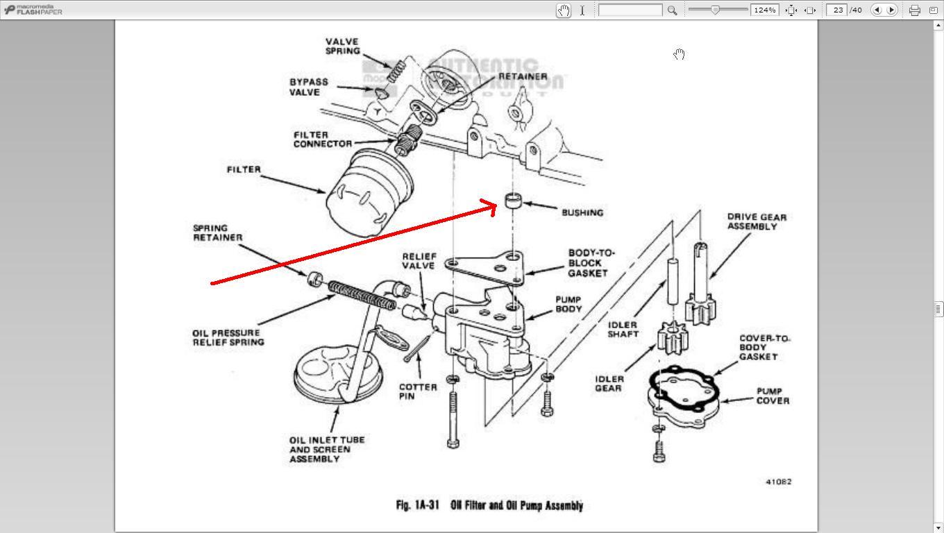
The rear main is the last cap on the engine block, closest to the flywheel (duh!).
We only need to remove this "last cap" that supports the crankshaft.
Do not even think about turning the crank over at all until we are all back together.chock your wheels, be in "neutral" with the transmission.
Take a minute to look at the design of the cap and how it is installed on the block- take a picture, if need be.
Using a 1/2 drive socket of the proper size, a 4" or so extension and a 1/2 drive ratchet. Back the two bolts out, till they are "hanging" by their last thread
Now, with your fingers, back 'em out all the way, - but leave them in the holes almost touching the block
They are now your "handles".
With one hand, grab both bolts and squeeze 'em together (hard!).
Gently-gently-gently rock the bolts fore and aft and sideways until the cap breaks loose
Gently lower the cap, do not turn it upside down! - (slinging, snatching it, or dropping it, will result in the "half moon" bearing half falling out/getting bent/getting dirty).
The other half of the bearing is still in the block above the crank it stays there. Moving the crank might move the bearing, so do not.
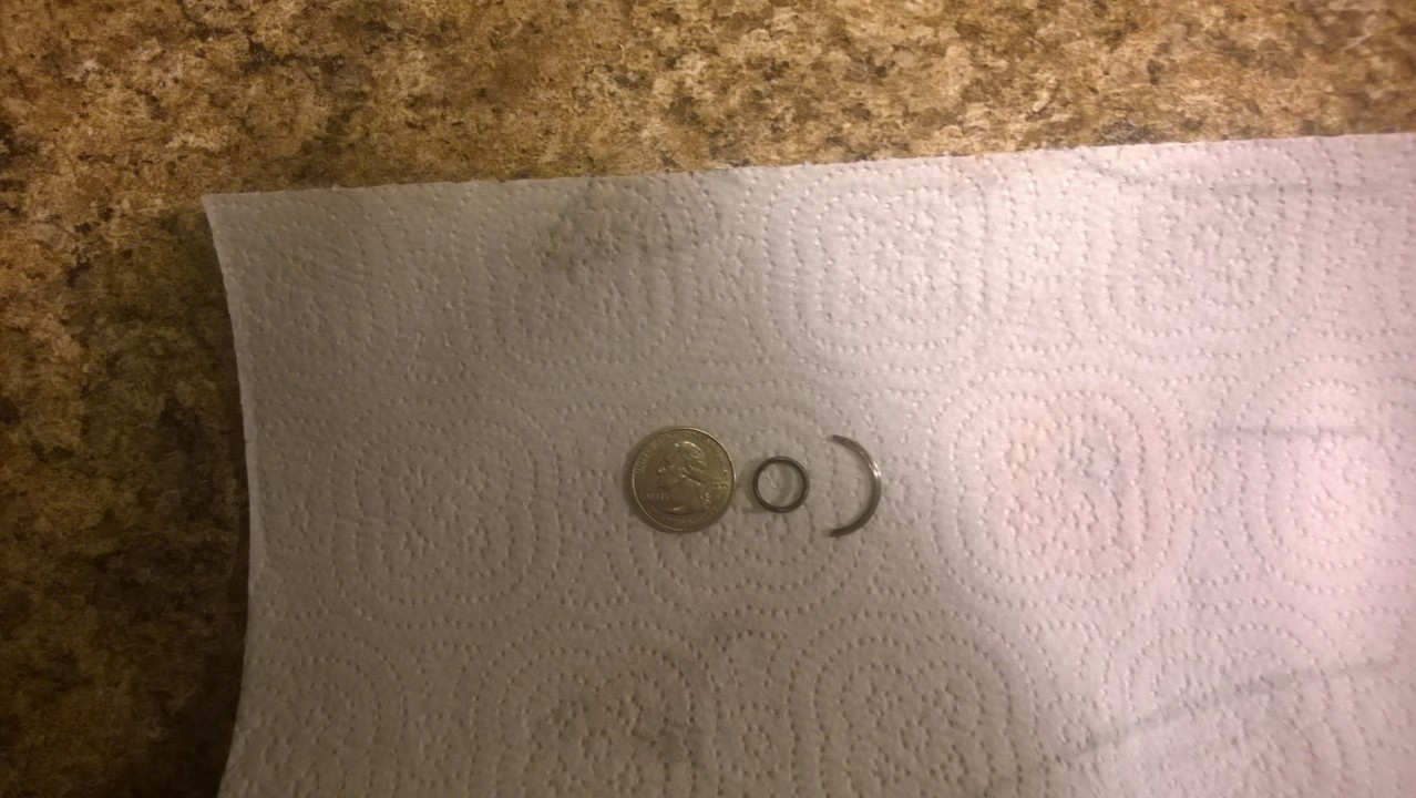
Warning (sort of) the lower bearing half could stick to the crank/or fall out, even being careful, it might fall out. If it did not get damaged, wipe it off really good and put it back in the cap. It should be obvious how it fits in (there is a groove that keys it in), the edges should be flush on both sides of the cap.
A "so called" good bearing will be smooth (it still may be worn) , if it has deep gouges in it, the rest of you bearings may be in the same boat, this maybe a sign of lack of oil lubrication. It is not a real good sign.


Yes, you can remove the bolts from the cap, once the cap is under your control
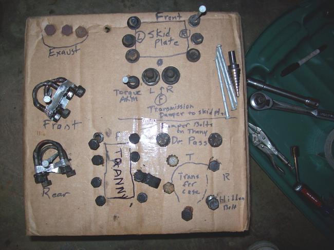
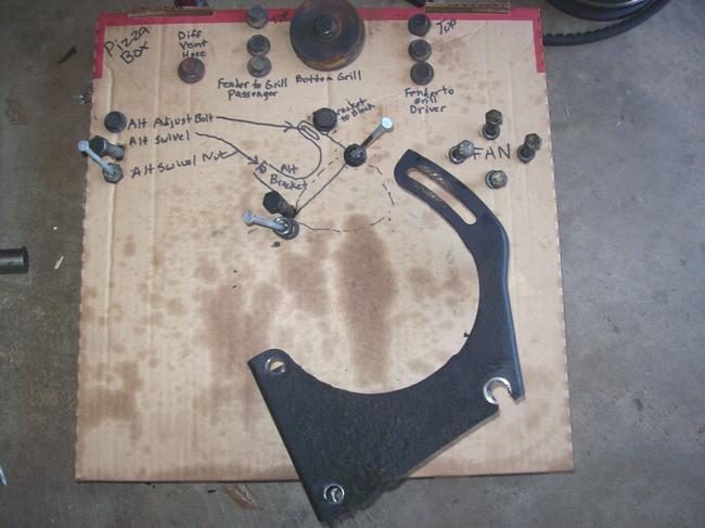
I always put bolts/ washers/ etc., back in the same holes and in the same direction, if at all possible, that they came out of. I use cardboard/ boxes/etc., to keep things in order. Normally, on the floor invites the kids or the dog to kick through them.
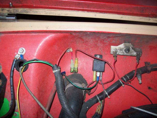
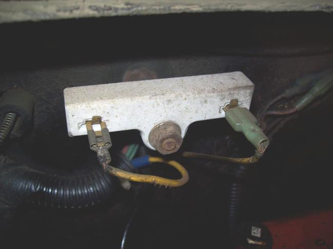
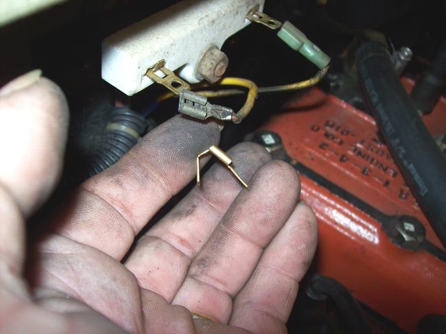
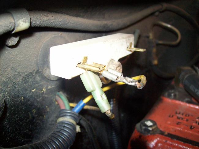
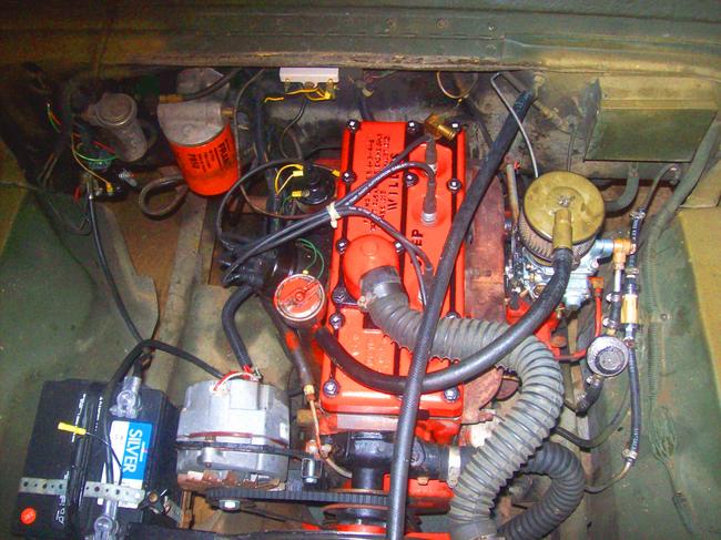
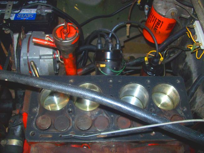
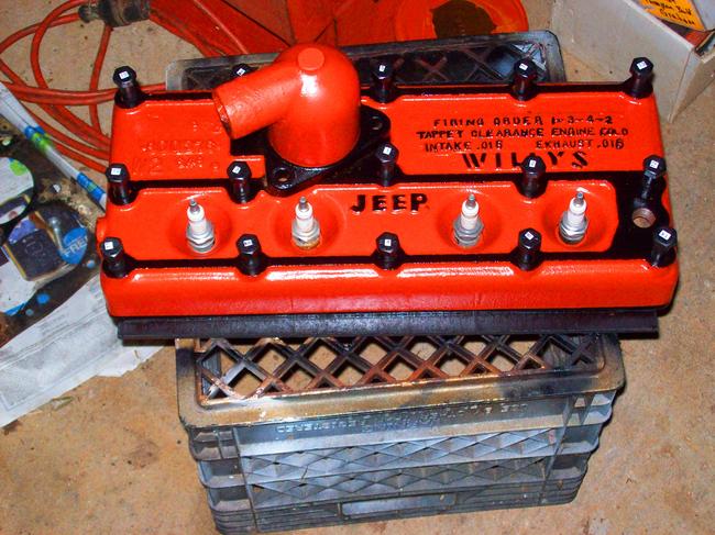
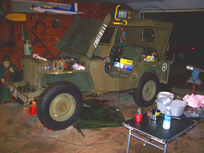
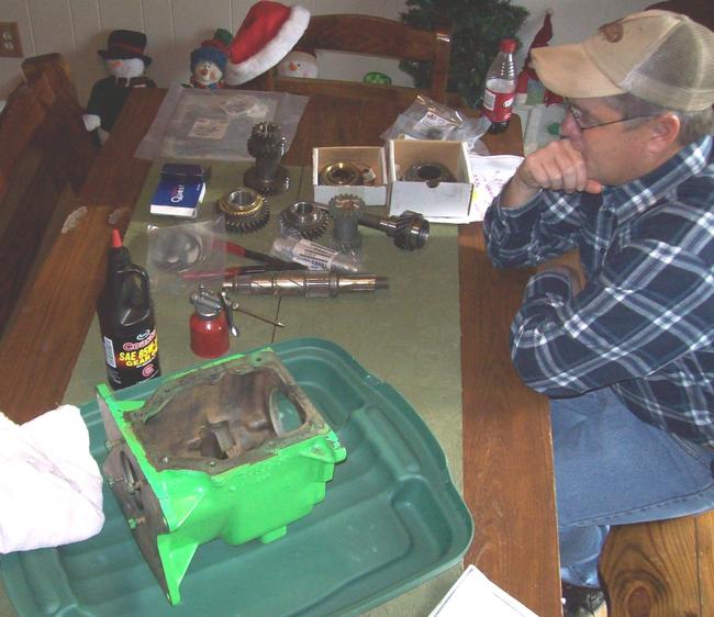
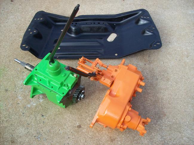
Below, see my pictures my "system" of transmission and timing chain repairs that i did to mine.
You will now see the rubber "ears" of the bottom half of the seal in the cap. Look at the shape of the ends of the actual seal part (not the ears).
The other half is in the block still, it has no ears. it has a definite shape that matches up with the bottom half (your new seal instructions may show you which way to "face the seal"- it may be written on the new seal).
This two piece seal (as with some one piece seals) is made to be directional. meaning, that when your crank is turning (in our case) clockwise, oil "wants" to push through the seal anyway. The seal has "fins" or raised "turbine like" diagonal hatches which sort of "sweep" the oil back inwards as the crank turns.


This is why it is going to be so important to get the upper half installed correctly.
The seal in the cap is a "no brainer" as far as direction-the one in the block requires some "thinking.
Lets use some brake cleaner on area on the block where the cap came from.
Clean the cap as well. Do not knock out the bearing half.
Remove the old seal from the cap clean some more if need be.
Install the new lower half seal (dry, when you put it in the cap).
With a very, very, very thin coat of Vaseline lubricate the half moon bearing surface a thin film, not a gob.
The same goes for the half moon rubber part of the seal. do not get any near/or on. The rubber "tips" that will "mate up" with the upper seal (these tips will soon have RVT silicone on them to seal them to the upper half of the seal) Vaseline/oil will not all them to bond. Lay it to the side. We have more to do on it later.

We will now extract the upper half.
Ever so carefully, with a small punch/piece of a brazing rod/etc., center up on one side of the rubber seal in the block. careful not to be on the block at all.
With a hammer, drive the seal in about a 1/4-1/2 inch.
The other side of the seal will protrude out of the other side. Grab it with some pliers remember, this puppy is "rotating out" pulling straight down will not get it out.
"inching it out", a little at a time, with the pliers close to the block is the trick.
Stop along the process and look at its direction (how it faces) so you will understand.


Now it is out!
Let's clean some more with the brake cleaner.
Now grab the new upper seal and give it a thin film of Vaseline- rotate/push it into the block with your fingers. remember it sort of has to start in the hole, but will "kind of" looking like it is the lower seal ( it will be a half circle on the lower side of the crank, in order to get it started in its hole).
Insure front is front and back is back.
If you get it in so far and it just do not want to go anymore with your fingers. you can use "smooth jawed" pair of pliers to continue pushing. i recommend pushing about a 1/4 inch at a time, 1/4 inch from the block-as not to "fold it over" by taking to big a bite at a time.
It is in!


It is flush/close to flush/if it protrudes slightly and evenly on both sides (just a little bit) that is fine. This will be a tight compression fit to the other half.
Once again, clean the seal ends with brake cleaner, the Vaseline got it to slide in, it now needs to come off for our RVT silicone to work right
Okay, now we are ready to assemble.
The new seal will keep the oil in around the shaft.
The cap itself (once installed) is gonna create a seam split/a tight fitting crack where it meets the block.


Yes, oil can squeeze through there.
So we are going to fix that!
On the block, where the cap "tucks in" there will be a step/rail/short wall that sandwiches it side to side.
We must add a teeny-weeny bit of silicone to the inside of this "wall" (the little corner) the full length of the little corner, do the same for the other side of the block.


Back to the cap.
Continue a by applying the RVT silicone on the flat machined surface around the bolt holes on the cap.
We must add a teeny-weeny bit of silicone to the ends of the seal in the cap (just where it mates up with the other half).
The amount of RVT silicone you use on a surface should be about the same thickness as the cardboard on your "corn flakes" box, a bit more will not hurt.
The cap will squish it and form a seal, most of it will squish out and get in the inside of the motor , so let's not use half a tube.
Time to get this on the road.
Insert your bolts into the cap, start the bolts evenly screw them up all the way by hand (if possible) and evenly the whole way.

Three things might happen now:
1) the cap will fit/seat, just with the finger tight bolts.
2) with the bolts tight by hand, a "love tap" with a block of wood and hammer in the center of the cap, might seat it.
3) alternating from one bolt to the other, a millionth of a turn each time, might seat it (i prefer the other two).


Once seated, grasp the head of your ratchet like a doorknob (do not lever using the handle) and "snug it" hard as you can with only that pressure.
Look at the cap with a good light, insure it is not "cocked" (backwards-ha!) All looks fine. now then, set torque wrench on 20 ft/lbs. Insure you are looking at the right scale (most have newton meters on one side and ft/lbs on the other (a YouTube class might aid you on setting the torque wrench correctly).
Torque each bolt to 20 ft/lbs, a "clicker type" torque wrench works better than an old needle type (but you must do what you must do!) I prefer doing "steps" if the torque spec is higher on my task.
Most clicker type torque wrenches "break" or "click" when the desired torque is reached. with mine, lower settings barely click, (i usually feel it break, as the click is so low, and may not be heard) so do not over do it.


So now, we must finalize with "80 ft/lbs" (which could have been done all at once, first go-round)(we will do this in a minute).
i like steps, just in case something went wrong, maybe i did not warp/break the item at this point in the game i could maybe "back out" with not damage.
Let's look at the cap again. Is all okay? Yes? Continue! torque both bolts to "80 ft/lbs" (we will not use additional steps to get there, as the bolt must turn a certain amount to reach proper torque) stop-stop-stop when it clicks.
I do not use "steps" with small torques like 50 ft/lbs and under, other than my initial snugging.
This is easier when building on an engine stand, underneath is a bit more challenging.


You have just installed the rear main seal
Inspect it again.
This whole deal can last for fifteen to thirty minutes, if you are with it. Take your time, you can go two hours if need be.


Oil pan procedure may come tomorrow!
It too has its quirks that you must pay special attention. To me, the oil pan is harder to do, as it is cumbersome.

The MEDIC


Sep 18, 2014 at 8:22 PM
Avatar
GPLOUCHARD
  • MEMBER
  • 26 POSTS
I got rear main in there correctly. Now I am waiting for the bushing on the oil pump, and priming the oil pump.
Sep 19, 2014 at 4:49 PM
Avatar
CJ MEDEVAC II
  • MEMBER
  • 222 POSTS
I have always used the four piece. Cork and rubber gasket set, as there were no other types available a while back.
I scrape off any old gasket, then i use brake cleaner to remove any oil from surfaces that get gasket-ed.
Now a days they have a one piece set (rubber) i have heard mostly good stuff about it, if installed as per the instructions.


http://shop.advanceautoparts.com/p/felpro-oil-pan-gasket-set-os-34308-r/5991498-P?searchTerm=oil+pan+gasket

This gasket, as with many others (rubber or cork), will scoot/ slide/push out from under the surfaces it is supposed to seal if you use "RVT silicone" on both sides of the gasket (at the same time- or i mean a "one step" installation).
Case in point, the valve cover gasket.
I usually use RVT silicone on the cover-and "a thousand" clothespins to hold it perfectly to the cover-then twenty four hours to dry with one side "dry", it cannot slip out between the bolt holes.
Then i RVT the bottom side of the gasket and install the valve cover to the head-and let it dry at least eight hours or so.

Normally the gasket gets sucked into/under the valve cover. they have no clue that the gasket is no longer between the two surfaces.
Keep me posted on progress and any questions!


The MEDIC
Sep 20, 2014 at 4:38 PM
Avatar
GPLOUCHARD
  • MEMBER
  • 26 POSTS
I really appreciate all the information. I am currently out of town for work, unplanned. I am not sure when my next day to work on it. I currently have oil pan cleaned up and gasket sitting on it so it has time to relax into shape. It is the one piece Felpro one. I tacked in place with small dabs of high temperature RTV.
Sep 20, 2014 at 5:30 PM