Wiring schematics needed

1977 JEEP CJ5
100,000 MILES • 5.9L • V8 • 4WD • MANUAL
Avatar
FRANK REID
  • MEMBER
  • 13 POSTS
To begin with my vehicle would crank if you jumped it off. It just wasn't charging the battery,but if you disconnected the battery cable it would shut off. I drove it to a shop bout 20 miles after a guy " helped me " wire it up correctly it just turns over but won't start. I need help with wiring diagrams. It's got a 360 in it I need to know how to completely rewire the alternator.ignition control module.coil.and distributor. I also am not good at wiring schematics. It gives me a headache just looking at them. Any help I can get would be great.
Aug 3, 2019 at 5:45 PM
Advertisement
Avatar
CJ MEDEVAC
  • CERTIFIED EXPERT
  • 11,004 POSTS
What type of ignition do you have? (Motorcraft, Prestolite, etc.)

The Medic
Aug 4, 2019 at 7:49 PM
Avatar
FRANK REID
  • MEMBER
  • 13 POSTS
I'm guessing Prestolite the wire color matches most diagrams I've been looking at. I got it to crank but it still doesn't charge the battery. I had to put a new ECM on it and it fired right up I need to know how to wire up the voltage regulator now I guess. Sorry for the late response.
Aug 5, 2019 at 5:02 PM
Advertisement
Avatar
CJ MEDEVAC
  • CERTIFIED EXPERT
  • 11,004 POSTS
Just want to see what we are looking at!

Can you remove the breather, lay your hood against the windshield?

Take a few left side, right side, overhead and well lit good pictures and post them?

You say it will run? We will get you charging again! This should not be a hard task.

I have some good, colored the wires myself, diagrams!

I too, have a 1977 CJ-5, he has a 258 6 cylinder now with a 4 barrel 390 Holley, I've upgraded many things, to include a Motorcraft ignition system (AMC started using in 1979, it is such an improvement over Prestolite)

The Medic
Aug 5, 2019 at 6:19 PM
Avatar
FRANK REID
  • MEMBER
  • 13 POSTS
This is my first jeep an it's driving me nuts not being able to figure it out. Someone has done away with the plugs on the wiring harness and have just added random wires. The only plugs I have are on the distributor, ECM. I'll take pictures for you tomorrow. I only have 3 wires coming fro inside I have 2 from fuse box and one coming from tachometer. it's got a 360 in it with a summit 650 dual feed carburetor. my wiring is a total nightmare.
Aug 5, 2019 at 6:40 PM
Avatar
FRANK REID
  • MEMBER
  • 13 POSTS
I'm pretty sure I inherited someone's nightmare headache.
Aug 6, 2019 at 5:00 AM
Avatar
CJ MEDEVAC
  • CERTIFIED EXPERT
  • 11,004 POSTS
Many diagrams from 1976-1986 have much of the same information.

My favorite all around is the 1979 schematic, it has Motorcraft ignition (which mine is upgraded to) lots of the rest is common to the other years.

Just so I don't have to re-write this explanation on how and why I colored my diagram.

See my 1st answer (SUNDAY, JULY 5TH, 2015 AT 7:41 AM) at this link

https://www.2carpros.com/questions/1979-jeep-cj5-wiring-issue

The two 1979 halves are at the bottom of that answer should you want to explore further. (like where the other end of wires wind up)

What I did now to make this easier for you to see is I chopped out everything except for the alternator stuff from the diagram.

I "arrowed" the fusible link that maybe has been overlooked.

See diagram below.

Let me know what you find or need!

The Medic
Aug 6, 2019 at 8:17 PM
Avatar
FRANK REID
  • MEMBER
  • 13 POSTS
Sorry I haven't had time to look at this. I worked 14 hours today. Thanks for all your help. Hopefully I'll have the time to go over it tomorrow.
Aug 7, 2019 at 6:37 PM
Avatar
CJ MEDEVAC
  • CERTIFIED EXPERT
  • 11,004 POSTS
We're always here!

Take your time.

The Medic
Aug 7, 2019 at 7:26 PM
Avatar
FRANK REID
  • MEMBER
  • 13 POSTS
Hey sorry I've been so busy I've decided to go with a 63a Delco Remy alternator. Can you show me a wiring diagram for this?
Aug 14, 2019 at 5:02 PM
Avatar
CJ MEDEVAC
  • CERTIFIED EXPERT
  • 11,004 POSTS
This is the one?

Pictures below.

The Medic
Aug 14, 2019 at 7:07 PM
Avatar
FRANK REID
  • MEMBER
  • 13 POSTS
Where is the wire go to from the #1 spot on the alternator?
Aug 15, 2019 at 3:38 PM
Avatar
CARADIODOC
  • CERTIFIED EXPERT
  • 34,306 POSTS
That's a common GM generator. If you're referring to the brown wire, that goes to the dash "Battery" warning light. With the ignition switch on, current flows through the bulb, then through that brown wire into the internal voltage regulator. You'll find the remaining approximately two volts at terminal 2. That is the turn-on signal that tells the regulator to turn on and start allowing current to flow through the generator's rotating field winding.

Besides the stationary coil of wire and the magnet, (electromagnet, in this case), the third needed ingredient is movement between them, to generate a voltage mechanically. That means the engine has to be running and the belt is spinning the field winding. At that point, an output voltage and current is produced. Part of that output current is tapped off and goes back to the regulator to tell it the charging system is working. When the regulator sees that, it puts 12 volts back out on the brown wire. With that 12 volts on one side of the bulb, and the battery's voltage on the other side of the bulb, the difference in voltage is near 0 volts, so the warning light turns off.

A common problem is a break in the circuit for that brown wire. A burned-out bulb is not sufficient to cause a no-charge condition because there is also a 510 ohm resistor on the instrument cluster to pass the start-up current in case the bulb has burned out. If there is a break in the brown wire, the regulator will not get the 12 volt signal to turn on, however, there is often enough residual magnetism in the core of the rotating field winding that it can self-excite and get a little output current started. All it takes is a tiny tickle of current, then the magnetic field will build and build on its own until it's strong enough for the regulator to step in. The symptom is typically a no-charge condition at first while the engine is idling, and it can take a few seconds to many minutes before charging starts. It has a much better chance of starting when engine speed is raised. Once charging starts, it will continue until the engine is stopped.

Terminal 1 is where the regulator senses system voltage. In this case it is tied right to the output wire which is tied to the positive battery cable. For some custom applications, that red jumper wire is placed internally inside the generator. The reason for having that terminal available outside is in some vehicles they want to measure system voltage at some remote point rather than right at the battery. For those vehicles that red wire will come from someplace else that still has full system voltage. On newer trucks in particular, GM had a real bad problem with flickering digital instrument clusters. To reduce that flicker, they tied this red wire right to the 12-volt feed at the cluster. It was more important to hold the voltage steady right there. The result was a slight fluctuation in system voltage at other places on the truck, but those other places, such as head lights, computers, and the radio, are not so susceptible to those fluctuations. It wasn't bad enough to notice, for example, flickering head lights.

As a temporary measure, when you're stranded with a break someplace in the brown wire, and the generator won't start up on its own, just use a stretched-out paper clip, or needle-nose pliers to momentarily touch terminals 1 and 2 together. That will put voltage on terminal 2 which will get charging started. From then on, the small input current is supplied by tapping off a small sample of the output current, so the system will keep right on running until you stop the engine.
Aug 15, 2019 at 4:16 PM
Avatar
FRANK REID
  • MEMBER
  • 13 POSTS
I'm getting no reading from alternator. I think I got a bad one at battery term on back of alternator meter reads 0.00.
Aug 15, 2019 at 4:26 PM
Avatar
CARADIODOC
  • CERTIFIED EXPERT
  • 34,306 POSTS
I can't find a diagram for this so we'll have to rely on my memory. If you're missing the 12 volts on the large output stud, (red arrow), that should be a solid piece of wire going back to the battery's positive cable. GM often ran it down to the large "Battery" cable stud on the starter solenoid as a convenient tie point, rather than running it back to the battery. That second wire could get overlooked when replacing the starter. They used that for other circuits too, so the entire electrical system could be dead if that wire is overlooked.

There is also going to be a fuse link wire spliced into that wire. Those can be hidden in the wiring harness somewhere because you aren't expected to have to get to them very often. A fuse link wire is a regular wire that is smaller in diameter than the wire it's spliced into, so it is the weak link in the chain. That piece only needs to be an inch or two long, but it's usually around four to six inches in length. This is a special piece of wire because its insulation is designed to not melt or burn. It will be a dull color compared to the normal shiny wires. The color denotes its current rating.

Where unsuspecting people get into trouble is when they replace their generator with one with a larger output current capacity. An AC generator will always only develop exactly the amount of current needed by the electrical system, and no more. Just because a generator with a larger capacity is installed, it isn't going to develop more current except for one condition. That is during a full-load output current test with a professional load tester. During that test, which lasts all of a few seconds, the generator is going to develop its maximum current it's designed to deliver. The fuse link wire was selected at the factory for the size of the generator installed there. While the rest of the output wire is capable of handling the maximum current of the largest generator available at the time, the fuse link wire is not. During the full-load output current test, an "upgraded" generator could develop more current than the fuse link wire is rated for, so that link could burn open.

While less common, if multiple high-current accessories are added to the vehicle, along with a larger generator, that combination could also overload the fuse link wire. A winch is a good example of that.
Aug 15, 2019 at 5:08 PM
Avatar
FRANK REID
  • MEMBER
  • 13 POSTS
I don't have any fuse links. Some one has ripped wiring out of jeep I have solid wires. I have a solenoid on the fire wall. That's where I have my alternator wire tied in but I touch the big red battery stud on back of alternator with ground on negative battery post I get no voltage.should I try to jump them like you said an see if it starts charging?
Aug 15, 2019 at 5:25 PM
Avatar
CJ MEDEVAC
  • CERTIFIED EXPERT
  • 11,004 POSTS
Go back to my diagram on TUESDAY, AUGUST 6TH, 2019 AT 8:17 PM

This shows everything alternator under the hood.

Here's the whole 1979 diagram. I colored it, any questions about it just ask!

The Medic
Aug 15, 2019 at 6:12 PM
Avatar
FRANK REID
  • MEMBER
  • 13 POSTS
I'll have to print it out when I try to enlarge the picture it gets distorted. My question is, when the engine is running shouldn't I be able to get 14 volts showing from back of alternator I'm getting nothing at the solenoid or the alternator. This is confusing me lol. I'm going to have to pay someone to fix it and I'm going to feel stupid because it's probably a simple fix.
Aug 15, 2019 at 6:24 PM
Avatar
CJ MEDEVAC
  • CERTIFIED EXPERT
  • 11,004 POSTS
This should be easy to check.

The Medic
Aug 15, 2019 at 8:07 PM
Avatar
FRANK REID
  • MEMBER
  • 13 POSTS
Okay, I'll check this when I get home from work. thank you for being patient.
Aug 16, 2019 at 5:22 AM
Avatar
CARADIODOC
  • CERTIFIED EXPERT
  • 34,306 POSTS
On CJ's first diagram, the fuse link wire is way at the top, right under the digit, "3". In his later post, it is drawn differently, but he has it circled. When you have an aftermarket wiring harness, or any other non-standard part, there's no way for us to know what someone else did, so we can only tell you what we know relative to standard parts. In this case, you have a GM charging system, and a Ford starting system. Ford uses the large "Battery" terminal on the starter solenoid as their convenient tie point. This is a good place for someone to make a mistake and connect the generator's wire to the wrong large stud. If that was done, you would find 12 volts on the generator's output stud only while you were cranking the engine. A better guess is that wire got overlooked and is not connected.

Regardless, you absolutely must have battery voltage, (12 volts), on the generator's output stud all the time. If 12 volts can't get from the battery to that stud, it can't get from the stud to the battery when the engine is running.
Aug 16, 2019 at 4:16 PM
Avatar
CJ MEDEVAC
  • CERTIFIED EXPERT
  • 11,004 POSTS
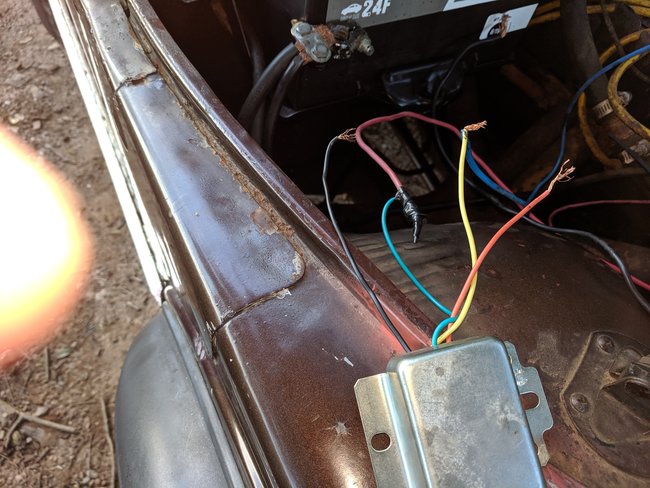
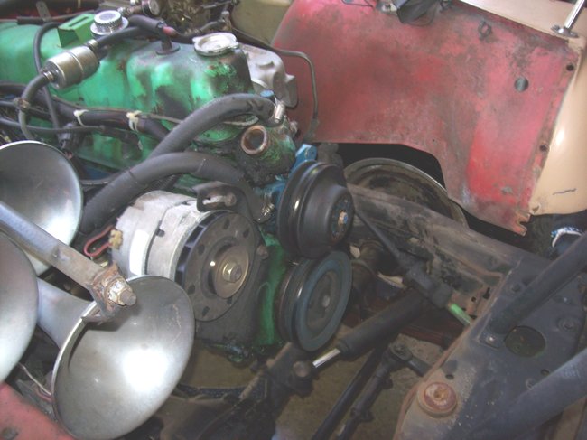
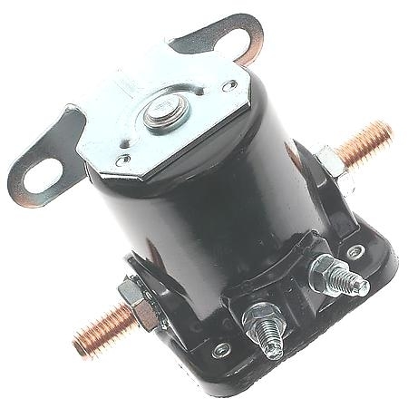
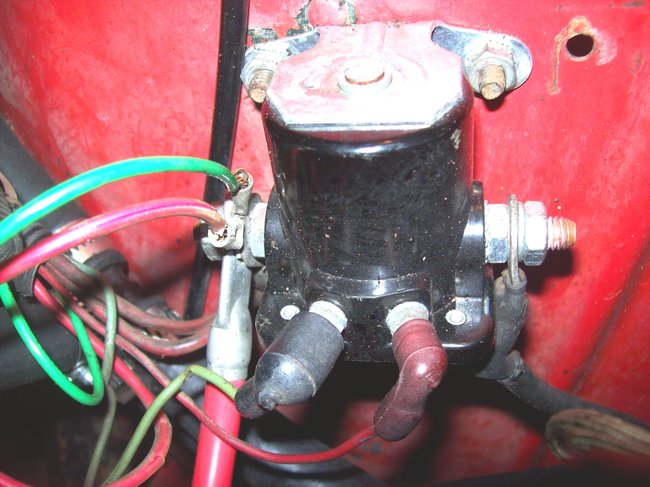
Ford (starter) solenoid mounted on fender.

We will orient it as in picture 1.

The 2 little studs we will call the front.

The one on the left is "S" (and always will be!) the one on the right is "I" (and always will be)-I don't care if you turn it around or upside down.

Usually the "S" and "I" are marked in/ on the plastic above the little studs.

To make this short and sweet!

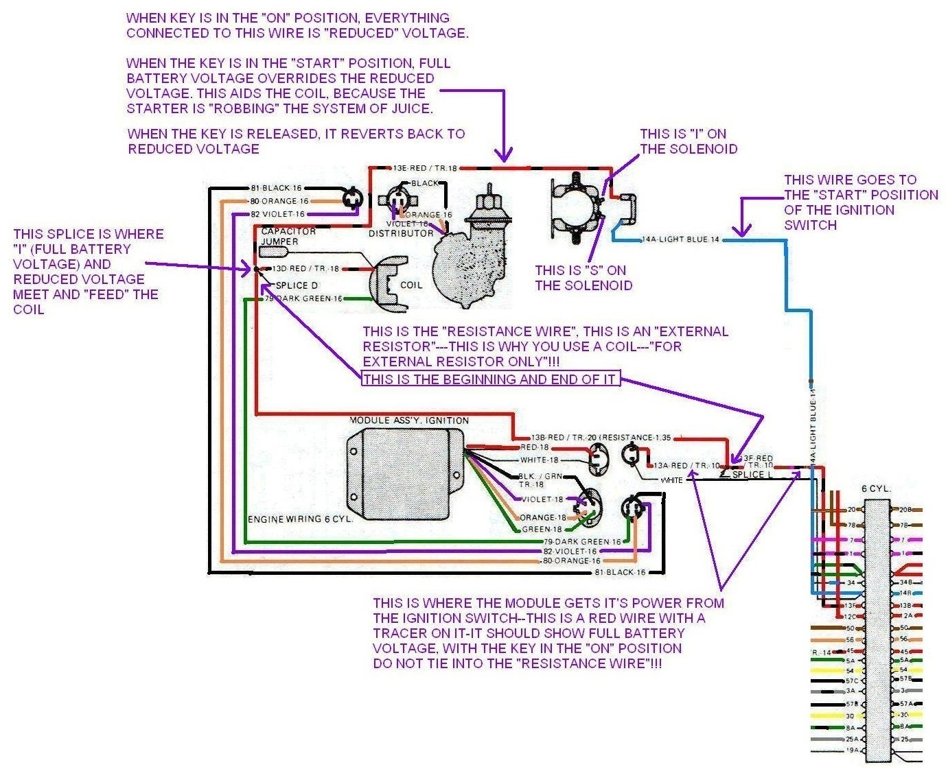
"S" is dead until 12 Volts is fed to it by way/ route to the ignition switch.

When the ignition switch gives it 12 volts (or you fake it out/ bypass the switch) the solenoid "activates" or engages the copper plates with in it.

These "so-called" plates are actually (in a manner of speaking) The big ole stud on the right temporarily connecting to the big ole stud on the left.

If the starter is not hooked to the solenoid at all, the solenoid will make a heavy click each time the key is turned to "start".

If everything is "right" and the starter is connected, turning the key to start should make the stater start spinning!

"I" ?

"I" gets power from the solenoid, it get's 12 volts, this 12 volts "assists" the coil with full voltage while the Jeep is being started (many Jeeps will not start without this assist)

Once you let go of the key, "I" 12 volts dies!

However, the voltage that now feeds the coil when the Jeep runs (Like let's say 7 volts) will travel down the "I" wire and will show 7 volts at the "actually dead" "I" terminal. I threw that in because at one time I did not understand why if it were dead, why does it have voltage?!

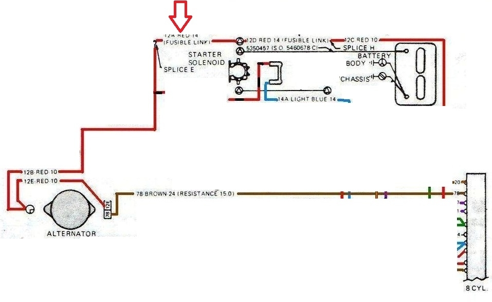
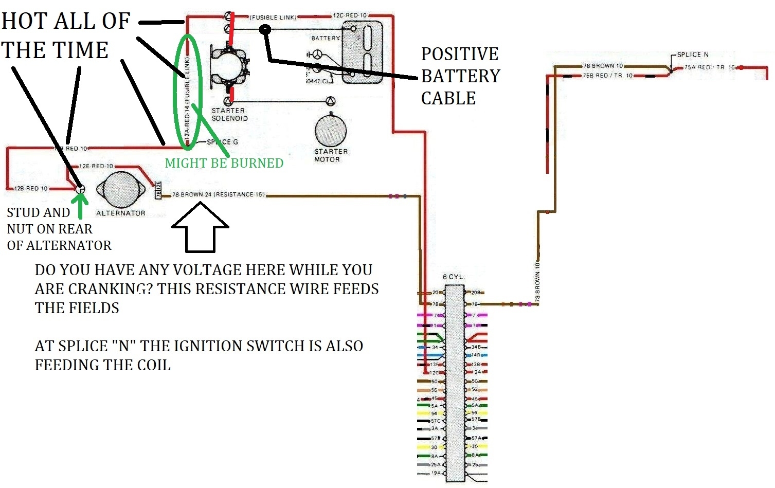
You can see why at the "tee" in my last diagram. That's the red wire off of the coil.

Now then

The funny part!

Those 2 big studs on the left and right.

Thinking in stupid terms.

Those two studs normally in the static position act like a solid bar with a cut down the middle (not connected to each other)

When the solenoid is activated, they act like "one" solid bar (connected together)

Here's the thing:

The solenoid does not care which side is which!

In fact, most Fords use the left big stud for the positive battery cable with all 12 volt feeds and the starter is "all by itself" on the right big stud (always by itself wherever you put it)

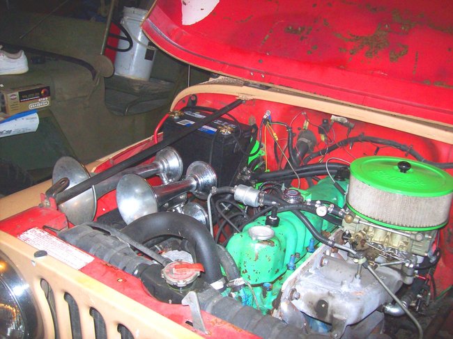
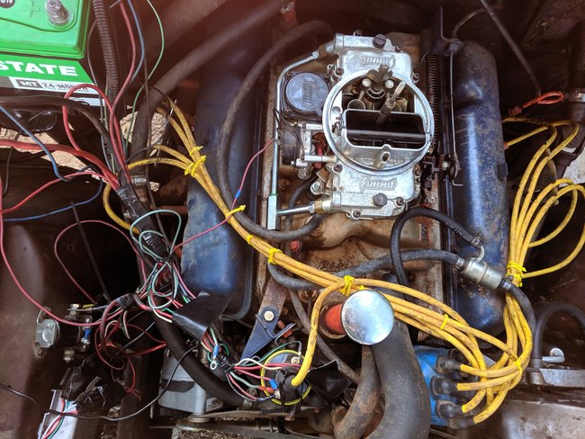
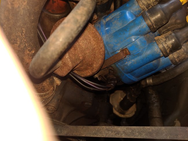
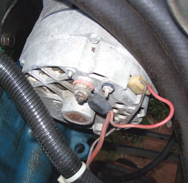
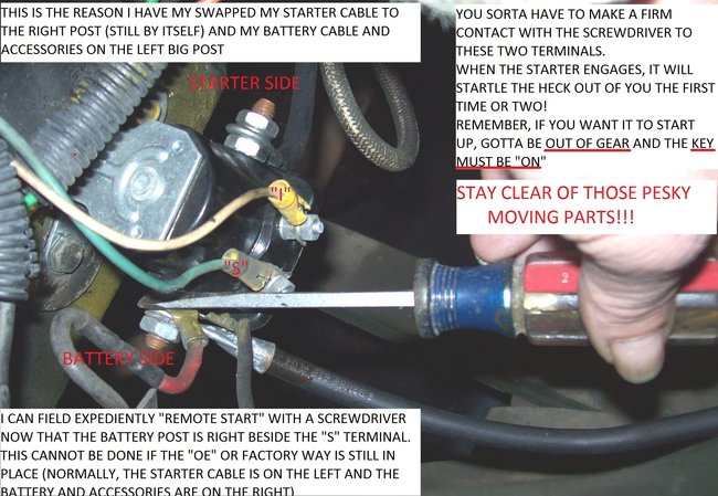
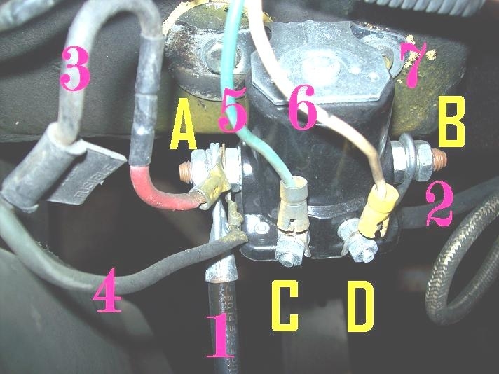
I do my both of my Jeeps this way, even though this is exactly opposite from how the Jeeps came from the factory! I have a good reason why I do this! See pic 2.

AMC (Jeep people from the 80's) Had their positive battery cable on the right big stud with all 12 volt feeds up against it and the starter was on the left big stud (again and always by itself!). All AMC Jeep diagrams show the solenoid connected in this manner. (Still, the solenoid don't care!)

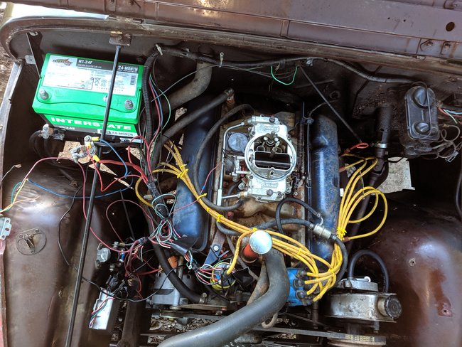
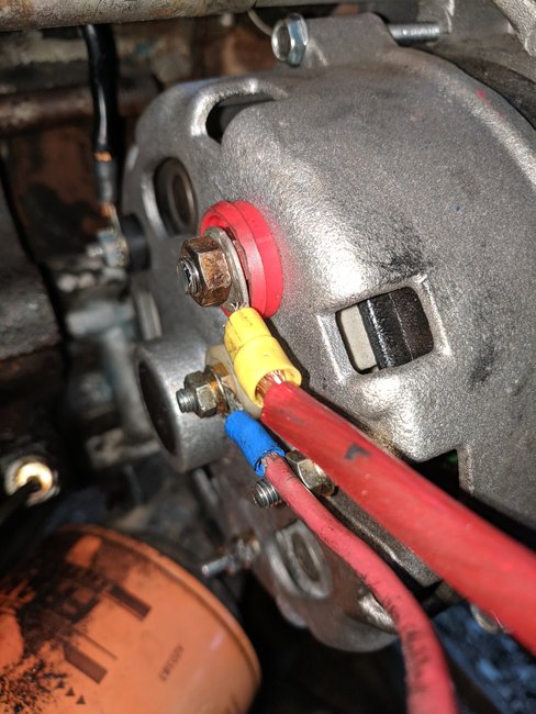
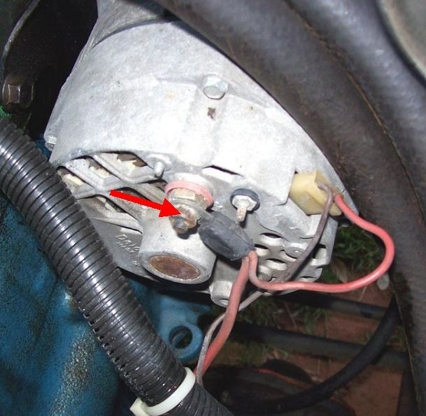
Picture 3 is my 1977

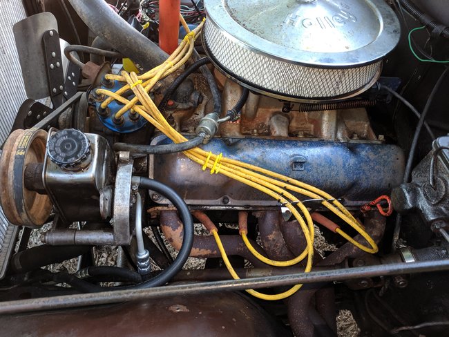
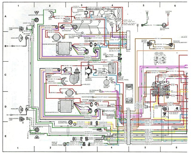
Picture 4 is my 1946 Willy's (which I wired to be mostly like a 1979). Wire "3" and wire "4" are fusible links. One is marked the other is not. The previous pic, 1977 also has fusible links, they are not labeled and are the two wires a little lower than the left big stud.

Moral of the whole long story.

Battery power and anything requiring battery power go together on the same big stud.

The starter goes all by itself on the other opposite big stud.

The Medic


Aug 17, 2019 at 11:22 AM
Avatar
FRANK REID
  • MEMBER
  • 13 POSTS
I think I've finally gotten it figured out. Thank you for all your help and time.
Aug 17, 2019 at 11:35 AM
Avatar
CJ MEDEVAC
  • CERTIFIED EXPERT
  • 11,004 POSTS
So did that novel actually help you or did you get tired of reading?

The Medic
Aug 17, 2019 at 6:48 PM
Avatar
FRANK REID
  • MEMBER
  • 13 POSTS
No I enjoyed the learning process. It actually helped me. I'm very grateful for the ones that understand all the wiring and can actually do it and know what they are talking about.
Aug 17, 2019 at 6:53 PM
Avatar
CJ MEDEVAC
  • CERTIFIED EXPERT
  • 11,004 POSTS
I like to see if the other side is actually catching on. Sometimes I get carried away and lose my audience.

Keep it up, update us all the way until you might feel comfortable driving him from one coast to the other. I like hearing confidence in one's own Jeep work!

The Medic
Aug 17, 2019 at 7:01 PM