power door lock wiring help?

2001 KIA RIO
104,000 MILES • 1.5L • 4 CYL • 2WD • AUTOMATIC
Avatar
1CRAZYGUIDO
  • MEMBER
  • 25 POSTS
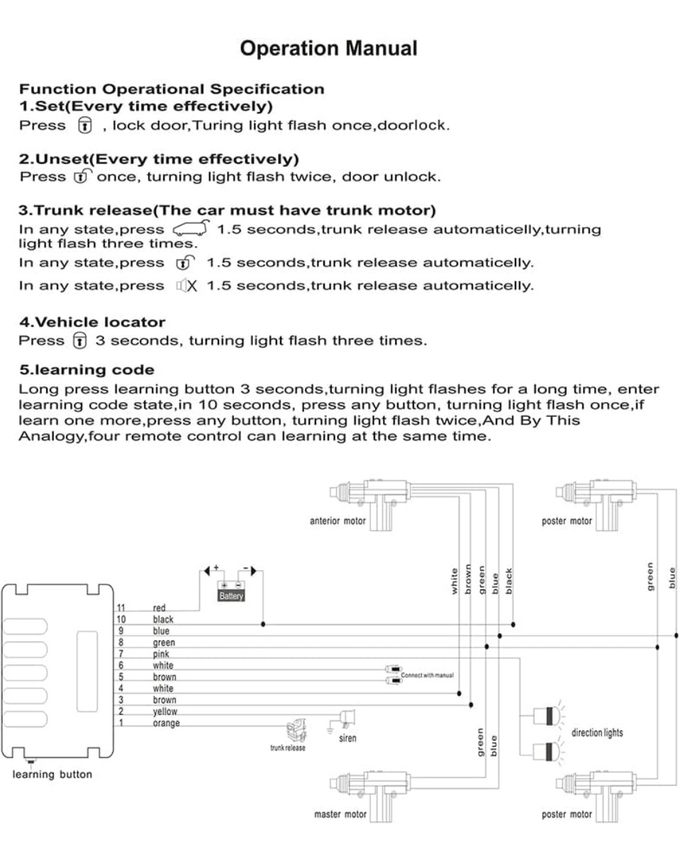
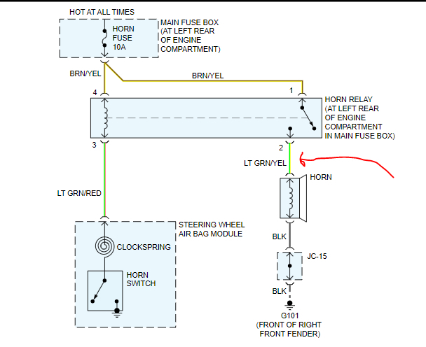
I’m currently in the process of installing aftermarket power door lock actuators and I’ve got everything wired up except the 2 pink wires that are supposed to be connected to the turn signals and the orange wire that is supposed to be connected to the horn if you could please let me know the easiest and best spot to tap into those wires I’d really appreciate it. The “brainbox” for the locks is in the driver's side kick panel and the wires are approximately 2 1/2 ft long. Sadly, that is all the instructions that came with the kit.
Oct 18, 2024 at 4:56 AM
Advertisement
Avatar
JACOBANDNICKOLAS
  • CERTIFIED EXPERT
  • 110,175 POSTS
Hi,

I'm sorry, but I can't read the wiring schematic you included. As far as the power supplies, they indicate to connect to the horn and turn signals? That really doesn't make sense to me. I could see where they could get constant power from the horn, but the signals only have power when the key is on.


Let me know. Hopefully, I will be able to figure this out for you.

Joe
Oct 18, 2024 at 9:30 PM
Avatar
1CRAZYGUIDO
  • MEMBER
  • 25 POSTS
Well, I tried to blow up wiring schematic so that maybe you could read a little better. Hopefully it was successful and you can see that the turn signal lights and the horn connections come from the brain box on, but those are essentially just so that when you hit the lock button, the horn will beep in the lights will flash let you know that the car actually has been locked so if you can help me figure out where to wire those into I would greatly appreciate it.
Oct 19, 2024 at 1:00 PM
Advertisement
Avatar
JACOBANDNICKOLAS
  • CERTIFIED EXPERT
  • 110,175 POSTS
Hi,

Looking at the schematic, the wires have to connect after the switches on the vehicle (horn button and signal switch). Power is supplied by the unit you purchased.

The horn is simple. There will be a light green wire with a yellow tracer going between the horn and the horn relay. It appears that is the wire where yellow wire you have will be spliced in. You indicated an orange wire in the original post, but that goes to the trunk.

Now, the signals are two separate circuits. I only see one pink wire in the schematic. We can't place a jumper wire between the left and right because that will cause both sides to flash when you signal. Is there only one pink wire?

Joe

See pic below.
Oct 19, 2024 at 7:59 PM
Avatar
1CRAZYGUIDO
  • MEMBER
  • 25 POSTS
Yes, there is one pink wire that splits off into two separate sections.
Oct 21, 2024 at 7:38 AM
Avatar
STRAILER
  • CERTIFIED EXPERT
  • 53,854 POSTS
Yes, on the wiring to the control unit there is simple battery power (red) and then a simple battery ground (black). I would find power by tapping into the ignition switch constant power which will be the blk/blu or the grn/red wires. Check out the images (below). Please let us know what happens.
Oct 22, 2024 at 9:53 AM