no spark from the ignition system?

1995 FORD F-150
375,000 MILES • 4.9L • 6 CYL • 2WD • MANUAL
Avatar
NOTANAUTOMECH
  • MEMBER
  • 1 POST
Replaced ICM, has new plugs, wires, alternator, starter, battery, distributor cap and rotor.
Oct 18, 2019 at 10:06 AM
Advertisement
Avatar
STRAILER
  • CERTIFIED EXPERT
  • 53,854 POSTS
Hello,

Do you have power at the coil? also it sounds like the PCM power relay is out. To be sure here is a guide and the location of the relay:

https://www.2carpros.com/articles/how-to-check-an-electrical-relay-and-wiring-control-circuit

This guide can help as well

https://www.2carpros.com/articles/how-to-test-an-ignition-system

Check out the diagrams (below). Please let us know what you find. We are interested to see what it is.
Oct 19, 2019 at 3:26 PM
Avatar
RANGER101
  • MEMBER
  • 2 POSTS
Ran fine stopped on day, no Spark,replaced coil, replaced pick-up coil, replaced ignition module, replaced computer, voltages check good, wires check good, grounds check good , fuses and relays check good, removed spout or computer conection get spark and truck will start and run for a few seconds and fuel pump runs none stop can you give me where to check next Thanks
Oct 14, 2020 at 2:00 PM (Merged)
Advertisement
Avatar
RASMATAZ
  • CERTIFIED EXPERT
  • 75,992 POSTS
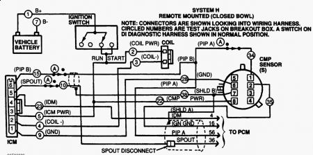
Fig. 5: Distributor Ignition System Wiring Diagram (5.0L)
PINPOINT TEST AA: NO START
Check For Codes Perform QUICK TEST. See TESTS W/CODES - EEC-IV (5.0L) article. If diagnostic trouble codes are present, service codes as necessary. If codes are not present, go to next step.
Check Battery Turn ignition on. Check battery voltage. If battery voltage is less than 12 volts, service battery as necessary. If battery voltage is more than 12 volts, go to next step.
Check For Spark Using Neon Bulb Spark Tester (D89P-6666-A), check for spark at coil wire while cranking. If spark is not present, go to next step. If spark is present, go to step 9).
Check For ICM Power Turn ignition off. Connect EEC-IV Diagnostic Cable (007-00097) to EEC-IV Breakout Box (T83L-50-EECIV), negative battery terminal and ICM. See Fig. 6 . Ensure PIP OPEN/NORMAL/SPOUT OPEN switch is in NORMAL position. Put DI overlay on breakout box.
WARNING:DO NOT connect EEC-IV Diagnostic Cable and PCM to EEC-IV Breakout Box simultaneously.

Turn ignition on. Put DVOM on DC voltage scale. Measure voltage between J5 (ICM PWR) and J7 (B -) at breakout box. If voltage is 10 volts or less, repair open in ICM PWR circuit to ICM. See Fig. 5 . If voltage is more than 10 volts, go to next step.
Fig. 6: Connecting EEC-IV Diagnostic Cable
Check PIP Signal Put DVOM on AC voltage scale. Measure voltage between J7 (B -) and J15 (PIP) while cranking engine. If AC voltage is not 3.0-8.5 volts, go to step 11). If AC voltage is 3.0-8.5 volts, go to next step.
Check SPOUT Signal Measure voltage between J7 (B -) and J10 (SPOUT) while cranking engine. If AC voltage is not 3.0-8.5 volts, go to step 18). If AC voltage is 3.0-8.5 volts, go to next step.
Check COIL PWR At Coil Turn ignition off. Connect diagnostic cable to ignition coil wiring harness connector. Leave ignition coil disconnected. Put DVOM on DC voltage scale. Turn ignition on. Measure voltage between J2 (COIL PWR) and J7 (B -). If voltage is 10 volts or less, repair open in ignition coil circuit. If voltage is more than 10 volts, go to next step.
Check COIL- Signal Turn ignition off. Connect B+ lead of diagnostic cable to positive battery terminal. Connect test light between J1 (B +) and J3 (COIL-). Crank engine. If test light does not flash brightly, go to step 27). If test light flashes brightly, replace ignition coil.
Check For Spark Using Neon Bulb Spark Tester (D89P-6666-A), check for spark at each spark plug wire while cranking. If spark is consistent at all spark plug wires, go to next step. If spark is not consistent, service distributor cap, rotor, plugs or plug wires.
Check Spark Plugs Remove and inspect spark plugs. Replace plugs as necessary. If spark plugs are okay, no-start condition is not ignition related. See appropriate H - TROUBLE SHOOTING (EEC-IV) - NO CODES article.
TESTS W/O CODES - EEC-IV (for Bronco)
TESTS W/O CODES - EEC-IV (for "E" Series RWD Van)
TESTS W/O CODES - EEC-IV (for "F" Pickup)
Check For CMP Power At CMP Sensor Connect diagnostic cable CMP (PIP) sensor tee to CMP sensor and wiring harness connector. Set DVOM to DC voltage scale. Measure voltage between J7 (B -) and J22 (CMP PWR) at breakout box. If voltage is 10 volts or less, repair open PIP PWR circuit. If voltage is more than 10 volts, go to next step.
Check For PIP From CMP Sensor Turn diagnostic cable switch to PIP OPEN position. Set DVOM to AC voltage scale. Crank engine and measure voltage between J7 (B -) and J34 (PIP A). If AC voltage is not 3.0-8.5 volts, check CMP sensor wiring and connector. Repair as necessary. If wiring and connector are okay, replace CMP sensor. If AC voltage is 3.0-8.5 volts, go to next step.
Check PIP With ICM Disconnected Turn ignition off. Turn diagnostic cable switch to NORMAL position. Disconnect diagnostic cable from ICM. Leave diagnostic cable attached to ICM wiring harness connector. Crank engine and measure voltage between J7 (B -) and J34 (PIP A). If AC voltage is 3.0-8.5 volts, replace ICM. If AC voltage is not 3.0-8.5 volts, go to next step.
Check PIP With PCM Disconnected Disconnect PCM. Crank engine and measure voltage between J34 (PIP A) and J7 (B -). If AC voltage is 3.0-8.5 volts, replace PCM. If AC voltage is not 3.0-8.5 volts, go to next step.
Check PIP To PCM For Short To Power Turn ignition off. Disconnect diagnostic cable from CMP sensor. Leave diagnostic cable attached to CMP sensor wiring harness connector. Set DVOM on DC voltage scale. Turn ignition on. Measure voltage between J7 (B -) and J34 (PIP A). If voltage is 0.5 volt or more, repair short to power in PIP/PIP A circuit between CMP sensor and PCM or ICM. If voltage is less than 0.5 volt, repair short to ground in PIP/PIP A circuit between CMP sensor and PCM or ICM.
NOTE:A break in step numbering sequence occurs at this point. Procedure skips from step 15) to step 18). No test procedures have been omitted.

18) Check For SPOUT In Harness If engine starts in this step, continue testing. Turn diagnost
Oct 14, 2020 at 2:00 PM (Merged)
Avatar
RANGER101
  • MEMBER
  • 2 POSTS
I have done all these steps, no signal from PIP with spout conected, pull spout and you have signal and engine starts, have replaced ICM and eec or Pcm 3 times no effect, connect spout you have no spark and fuel pump runs without timing out it also runs with spout in??????? all voltages are correct and have Ohmed to check for wire breaks all check good conections.
Oct 14, 2020 at 2:00 PM (Merged)
Avatar
BOBBY BARREL
  • MEMBER
  • 2 POSTS
I had all the same issues with my 1995 ford 150 and I figured out the problem! After distributor cap rotor wires plugs mass flow air sensor battery ignition module coil pack coil The only thing I didn't do was put a new brain and it. Sometimes it is just the easiest fix You bypass. If people are still having the problems I will tell you the answer.
Oct 14, 2020 at 2:00 PM (Merged)
Avatar
BOBBY BARREL
  • MEMBER
  • 2 POSTS
It was a big 20 amp fuse in the main fuse panel box underneath the hood all the way at the top yellow fuse.
Fired up first time. If you disconnect and reconnect the ignition module too many times it will trip that fuse and you will have no spark. I learned the hard way
Oct 14, 2020 at 2:00 PM (Merged)
Avatar
STRAILER
  • CERTIFIED EXPERT
  • 53,854 POSTS
Nice work bobby
Oct 14, 2020 at 2:00 PM (Merged)
Avatar
ZPAINE
  • MEMBER
  • 9 POSTS
shortly after buy the truck, i had a no spark issue, only died once. if it started it would drive anywhere. but sometimes it wouldn't start, becoming more frequent until i can no longer drive it. when there is no spark there is no power to coil. coil distributor, icm, coil, computer, ignition switch, and the voltage regulator are all new. any ideas?
Oct 14, 2020 at 2:01 PM (Merged)
Avatar
JACOBANDNICKOLAS
  • CERTIFIED EXPERT
  • 110,175 POSTS
Has the check engine light come on?
Oct 14, 2020 at 2:01 PM (Merged)
Avatar
ZPAINE
  • MEMBER
  • 9 POSTS
nope
Oct 14, 2020 at 2:01 PM (Merged)
Avatar
JACOBANDNICKOLAS
  • CERTIFIED EXPERT
  • 110,175 POSTS
Try switching the EEC relay with one that has the same part number. Let me know if that changes things.
Oct 14, 2020 at 2:01 PM (Merged)
Avatar
ZPAINE
  • MEMBER
  • 9 POSTS
truck ran for about 2 days then nothing, hasn't started for 2 days now, no spark
Oct 14, 2020 at 2:01 PM (Merged)
Avatar
JACOBANDNICKOLAS
  • CERTIFIED EXPERT
  • 110,175 POSTS
First, sorry about the delay in getting back to you. I lost my father this week and things have been...

Did it start running after replacing the EEC or on its own?
Oct 14, 2020 at 2:01 PM (Merged)
Avatar
ZPAINE
  • MEMBER
  • 9 POSTS
on its own
Oct 14, 2020 at 2:01 PM (Merged)
Avatar
JACOBANDNICKOLAS
  • CERTIFIED EXPERT
  • 110,175 POSTS
Did you try switching the EEC? If there is no power to anything, then the next step is the PCM because you replaced everything.
Oct 14, 2020 at 2:01 PM (Merged)
Avatar
ZPAINE
  • MEMBER
  • 9 POSTS
the pcm is the computer that stubs through the fire wall next to the elec. terminal on the drivers side, thats new, the 2nd one, which leads us to the wiring harness. i've checked every wire for continuity while wiggling the terminals and wires, no loss.
Oct 14, 2020 at 2:01 PM (Merged)
Avatar
ZPAINE
  • MEMBER
  • 9 POSTS
i have power everywhere except the coil, but have power with the terminals pulled off the coil. the engine will crank until the battery dies.
Oct 14, 2020 at 2:01 PM (Merged)
Avatar
JACOBANDNICKOLAS
  • CERTIFIED EXPERT
  • 110,175 POSTS
You lose power to the coil only when it is connected?
Oct 14, 2020 at 2:01 PM (Merged)
Avatar
ZPAINE
  • MEMBER
  • 9 POSTS
only when connected, tried swaping it out, same deal
Oct 14, 2020 at 2:01 PM (Merged)
Avatar
JACOBANDNICKOLAS
  • CERTIFIED EXPERT
  • 110,175 POSTS
The supply, (PCM), must not be able to handle the load.
Oct 14, 2020 at 2:01 PM (Merged)
Avatar
ZPAINE
  • MEMBER
  • 9 POSTS
??? not sure what you mean. its getting hot or there are a lot of loose/dirty connections, the pcm can not handle it?
Oct 14, 2020 at 2:01 PM (Merged)
Avatar
JACOBANDNICKOLAS
  • CERTIFIED EXPERT
  • 110,175 POSTS
Many times an electrical component will register at a normal voltage until a load is placed on it. At that point, if there is a bad connection or the component can't keep up with the load, the voltage drops.
Oct 14, 2020 at 2:01 PM (Merged)
Avatar
ZPAINE
  • MEMBER
  • 9 POSTS
so are we talking about the computer(pcm) in the fire wall, or the icm on the fender wall
Oct 14, 2020 at 2:01 PM (Merged)
Avatar
JACOBANDNICKOLAS
  • CERTIFIED EXPERT
  • 110,175 POSTS
PCM, but check wiring for corrosion, damage...
Oct 14, 2020 at 2:01 PM (Merged)
Avatar
SHOCKED
  • MEMBER
  • 3 POSTS
I have no spark changed coil and ignition module still no spark Ihave power to both what should I do?
Oct 14, 2020 at 2:02 PM (Merged)
Avatar
F4I_GUY
  • CERTIFIED EXPERT
  • 3,302 POSTS
Check for a signal from the PCM.

If there is no signal, start looking at the cam or crank sensors. Do you have any check engine lights on?
Oct 14, 2020 at 2:02 PM (Merged)
Avatar
SDICO
  • MEMBER
  • 3 POSTS
i rebuilt the engine & transmission (was a Ford tech for 20 years , but previous to this eec). Have no spark from the coil. Replaced the coil & distributor with known good running identical truck, still no spark. Checked cam/crank timing (both gear marks pointing to each other) Info I've found online suggests there is no TFI, but appears to be one on driver's fender well next to firewall. Also, assume the sensor on top of the block behind intake is cam position sensor; could this be bad?
Oct 14, 2020 at 2:02 PM (Merged)
Avatar
MERLIN2021
  • CERTIFIED EXPERT
  • 17,250 POSTS
If your ignition module is on the fender, it's duraspark, not TFI...and either the the duraspark module is the problem, or cam sensor. Here's a wiring digram to help with testin, check for power at coil and at the module... also check PCM power relay in the under hood fuse block.


https://www.2carpros.com/forum/automotive_pictures/62217_igna_1.jpg

Check relay #1 And fuse #22


https://www.2carpros.com/forum/automotive_pictures/62217_relaya_1.jpg

Oct 14, 2020 at 2:02 PM (Merged)
Avatar
SDICO
  • MEMBER
  • 3 POSTS
The module mounted on the fender well (ICM, I believe) is identical to the one that was on some models mounted to the distributor, and has an oblong connector. When mounted to the inner fender, it is mounted to a heat sink. The sensor on the back of the block is the knock sensor. (Verified by comparing parts at parts house.) I substituted the relay from the running truck, along with the icm & the distributor & coil. Still no spark. I put the parts from the non-running truck on the other truck, and the truck ran fine. I guess all that remains is the computer under the dash?
Oct 14, 2020 at 2:02 PM (Merged)
Avatar
MERLIN2021
  • CERTIFIED EXPERT
  • 17,250 POSTS
Or the ignition switch and fuses. Also read the codes, like this: Jump the two termnals shown together and turn key to "ON" and count the flashes... a 22 will flash as 2 flashes then a short pause, then 2 flashes, if more than one code is stored, the pause will be longer. The codes will display three times and end with 11 or 111. Write them down and post here. First do this with the key on engine off, then again with it running.


https://www.2carpros.com/forum/automotive_pictures/62217_Pre_95_FordJump_4.jpg

Oct 14, 2020 at 2:02 PM (Merged)
Avatar
SDICO
  • MEMBER
  • 3 POSTS
also tried swapping computers - both work in the running truck, neither work in the non-running truck. I read the codes; 116, 565, and 636. one is evap. solenoid, I verified that it opens the vacuum line when ign is in, another is engine coolant temp sensor out of range, the sensor is brand new. Won't it be out of range until the truck is running? Third is trans. temp. sensor, since trans was also rebuilt, there is probably no fluid contact yet, since trans has not been completely filled? Is there a way to check these sensors w/ a volt/ohmmeter? The connections at the coil show battery voltage on the right connector with ign. on, while cranking, left connector shows 3 volts less than battery voltage. Coil has also been replaced, as terminal tip was broken. I've checked wiring & connectiors, no visible problems or corrosion. I've replaced fuses and the relay. I'm stumped!
Oct 14, 2020 at 2:02 PM (Merged)
Avatar
MERLIN2021
  • CERTIFIED EXPERT
  • 17,250 POSTS


https://www.2carpros.com/forum/automotive_pictures/62217_ECTGM_3.jpg

Test ECT with your ohm meter, If the battery neg cable has been disconnected for several minutes, the KAM should have cleared these codes..also it could be the distributor with a no spark. Or ignition switch.
Oct 14, 2020 at 2:02 PM (Merged)
Avatar
BRIAN7388
  • MEMBER
  • 2 POSTS
i have a 95 ford f-150 I-6 4.9L. it usually starts and runs great but, every now and then it will cut off completely while driving as if the ignition was turned off. i wait anywhere between 5-30 minutes and the truck will start and run fine after this. or the other case is sometimes when i go to start it, it will crank and crank until the battery dies-i know this is because of no spark...ignition control module, ignition coil, plugs, and wires were replaced, help?
Oct 14, 2020 at 2:02 PM (Merged)
Avatar
JACOBANDNICKOLAS
  • CERTIFIED EXPERT
  • 110,175 POSTS
Spark:

When this happens, are you getting power to the coil? Also, have you checked the crank sensor? Has the check engine light come on?

Let me know.
Oct 14, 2020 at 2:02 PM (Merged)
Avatar
BRIAN7388
  • MEMBER
  • 2 POSTS
I have not checked either the crank sensor or power to the coil. Where is the crank sensor located? If that was the issue it would still crank and not kick over? And yes the check engine light came on a little bit ago, but I do not think it's related. The codes I got from the test were 522-(not in park or neutral, but it was in nuetral..), 732-(not listed in the codes), 334-(egr closed voltage higher than expected). And what's the best way to check power to the coil??
Thanks,
Brian
Oct 14, 2020 at 2:02 PM (Merged)
Avatar
TEDMAN
  • MEMBER
  • 1 POST
The truck has had 2 ignition control modules installed in the last 6 months,(by others) and now the same symptoms are back. The truck turns over but Im not getting any spark to the distributor cap. Its throwing out a code 212 and 452. Im suspect of the igintion control module again, but wonder what could be killing these things? Also I would like to know where the module is located and how to change it myself.....Im out of $$ and desprately need my truck....thank you
Oct 28, 2020 at 11:44 AM (Merged)
Avatar
IN13PIECES
  • MEMBER
  • 3 POSTS
Hey,

Try looking in the engine compartment on the driver's side wall. It might be located there, or right next to the distributor. It's usually either a silver or black box-like object.

I've heard that similar electrical problems can be caused my the distributor getting excess moisture on it. Have you check for any excess water getting under your hood? How about wiring?

Good luck.
Oct 28, 2020 at 11:44 AM (Merged)
Avatar
DAVE H
  • CERTIFIED EXPERT
  • 13,384 POSTS
Ignition Control Module (ICM)On left rear side of inner fender panel. See Fig. 1 .


https://www.2carpros.com/forum/automotive_pictures/266999_icm_1.jpg

1) Continuous Memory Code 211 Code 211 indicates 2 successive erratic Profile Ignition Pick-Up (PIP) pulses occurred, resulting in a possible engine miss or stall. Check for the following possible causes of fault: Loose wires or connectors. Secondary ignition short to ground. On-board transmitter equipment (2-way radio). Repair if necessary and repeat QUICK TEST. If problem is not found, go to next step. If vehicle does not start, go to CIRCUIT TEST AA. 2) Continuous Memory Code 212: Check IDM Circuit Continuity -Continuous Memory Code 212 indicates loss of IDM input to PCM. Possible causes for this fault are: Open or shorted circuit in wiring harness. Faulty ICM. Faulty PCM. If vehicle does not start, go to CIRCUIT TEST AA. If vehicle starts, go to next step. 3) Check IDM Circuit Continuity Turn ignition off. Disconnect 60-pin PCM connector. Inspect terminals and repair if damaged. Install EEC-IV Breakout Box (T83L-50-EEC-IV), leaving PCM disconnected. Disconnect ICM. Measure resistance between test pin No. 4 at breakout box and IDM terminal at ICM wiring harness connector. If resistance is 5 ohms or less, go to step 5). If resistance is more than 5 ohms, repair open circuit, and repeat QUICK TEST. NOTE:A break in step numbering sequence occurs at this point. Procedure skips from step 3) to step 5). No test procedures have been omitted. 5) Check IDM Circuit For Short To Power (Except VREF) Turn ignition off. Leave ICM and PCM disconnected. Measure voltage between breakout box test pin No. 4 and negative battery terminal. Turn ignition on. Measure voltage between test pin No. 4 and test pins No. 40 and 60 at breakout box. If voltage is more than 10.5 volts, repair short circuit. Clear codes, and repeat QUICK TEST. If voltage is 10.5 volts or less, go to next step. 6) Check IDM Circuit For Short To PIP & VREF Turn ignition off. Leave PCM and ICM disconnected. Disconnect ignition coil wiring harness connector (non-CCD). Remove scan tester (if applicable). For short to PIP, measure resistance between test pins No. 4 and 56 at breakout box. For short to VREF, measure resistance between test pins No. 4 and 26 at breakout box. If any resistance is 10,000 ohms or less, repair short circuit and repeat QUICK TEST. If each resistance is more than 10,000 ohms, go to next step. 7) Check IDM Circuit For Short To Ground Turn ignition off. Remove scan tester (if applicable). Leave ignition coil, ICM and PCM disconnected. Measure resistance between test pin No. 4 and test pins No. 20, 40, 46 and 60 at breakout box. If each resistance is more than 10,000 ohms, reconnect scan tester and go to next step. If any resistance is 10,000 ohms or less, repair short to ground in IDM circuit. Clear codes, and repeat QUICK TEST. 8) Check ICM Turn ignition off. Connect PCM to breakout box. Reconnect ICM and ignition coil to wiring harness connectors. Connect DVOM between test pins No. 4 and 16 at breakout box. Start engine. Observe DVOM for voltage surge while lightly tapping on ICM and Camshaft Position (CMP) sensor to simulate road shock. Wiggle all ICM and CMP sensor wiring and harness connectors. If fault (voltage surge) is indicated, disconnect and inspect wiring harness connectors and terminals for damage. If fault is not indicated, go to next step. 9) Check PCM & Harness Connectors Ensure engine is still running and DVOM is still connected between test pins No. 4 and 16 at breakout box. While observing DVOM, wiggle and bend wiring harness, a small section at a time, from ICM and CMP sensor (if equipped) to cowl. Also check harness from cowl to PCM. If fault is indicated, isolate fault and repair as necessary. Remove breakout box, reconnect all components, and repeat QUICK TEST. If no fault is found, go to next step. 10) Check PCM & Harness Connectors Turn ignition off. Disconnect PCM 60-pin connector. Inspect connector for damaged pins, corrosion and loose wires. If connector is damaged, repair as necessary. Clear codes, and repeat QUICK TEST. If connector is okay, go to next step. 11) Check PCM For Short To Power Turn ignition off. Connect PCM to breakout box. Disconnect CMP wiring harness connector. Measure voltage between test pin No. 4 at breakout box and chassis ground. Turn ignition on. Measure voltage between test pin No. 4 and test pins No. 40 and 60 at breakout box. If either voltage reading is more than 10.5 volts, replace PCM and repeat QUICK TEST. If both voltage readings are 10.5 volts or less, go to next step. 12) Check PCM For Short To Ground Turn ignition off. Leave PCM connected to breakout box. Measure resistance between test pin No. 4 and test pins No. 40, 46 and 60 at breakout box. If resistance is more than 10,000 ohms, check ignition system. See SYSTEM/COMPONENT TESTS - EEC-IV (5.0L) article. If resistance is 10,000 ohms or less, replace PCM and repeat QUICK TEST. ****CODE 452.....Insufficient Input From Vehicle Speed Sensor To Powertrain Control Module***
Oct 28, 2020 at 11:44 AM (Merged)