Again, do you have a code?
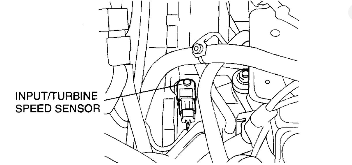
If the input speed sensor was the issue it would not shift as that signal is critical for shifting. the location is in the diagrams below.
If you have an advanced scan tool you can monitor the sensor readings.
Roy
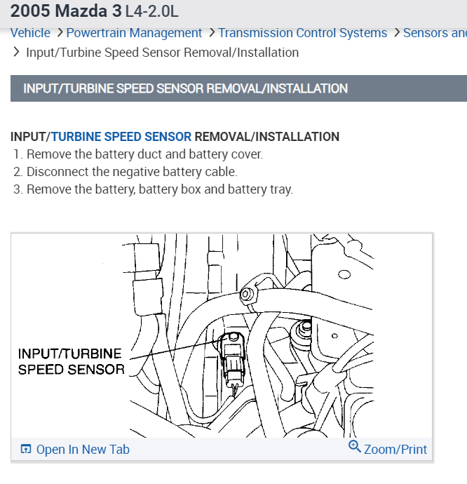
NPUT/TURBINE SPEED SENSOR REMOVAL/INSTALLATION
1. Remove the battery duct and battery cover.
2. Disconnect the negative battery cable.
3. Remove the battery, battery box and battery tray.
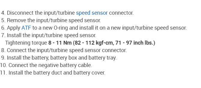
4. Disconnect the input/turbine speed sensor connector.
5. Remove the input/turbine speed sensor.
6. Apply ATF to a new O-ring and install it on a new input/turbine speed sensor.
7. Install the input/turbine speed sensor.
Tightening torque 8 - 11 Nm (82 - 112 kgf-cm, 71 - 97 inch lbs.)
8. Connect the input/turbine speed sensor connector.
9. Install the battery, battery box and battery tray.
10. Connect the negative battery cable.
11. Install the battery duct and battery cover.
Testing
INPUT/TURBINE SPEED SENSOR INSPECTION
Caution: Water or foreign material entering the connector can cause a poor connection or corrosion. Be sure not to drop water or foreign material on the connector when disconnecting it.
1. Remove the battery duct and battery cover.
2. Disconnect the negative battery cable.
3. Remove the battery, battery box and battery tray.
4. Disconnect the input/turbine speed sensor connector.
5. Measure the resistance between the input/turbine speed sensor terminals. If there is any malfunction, replace the input/ turbine speed sensor.
Resistance 250 - 600 ohms (ATF temperature: 40 - 160°C (-40 - 320°F))
6. Connect the input/turbine speed sensor connector.
7. Install the battery, battery box and battery tray.
8. Connect the negative battery cable.
9. Install the battery duct and battery cover.
Check out the diagrams (Below). Please let us know if you need anything else to get the problem fixed.
Apr 18, 2019 at 5:10 PM