Engine vacuum diagrams

1988 MAZDA RX7
900 MILES • 2WD • MANUAL
Avatar
REDBUG
  • MEMBER
  • 6 POSTS
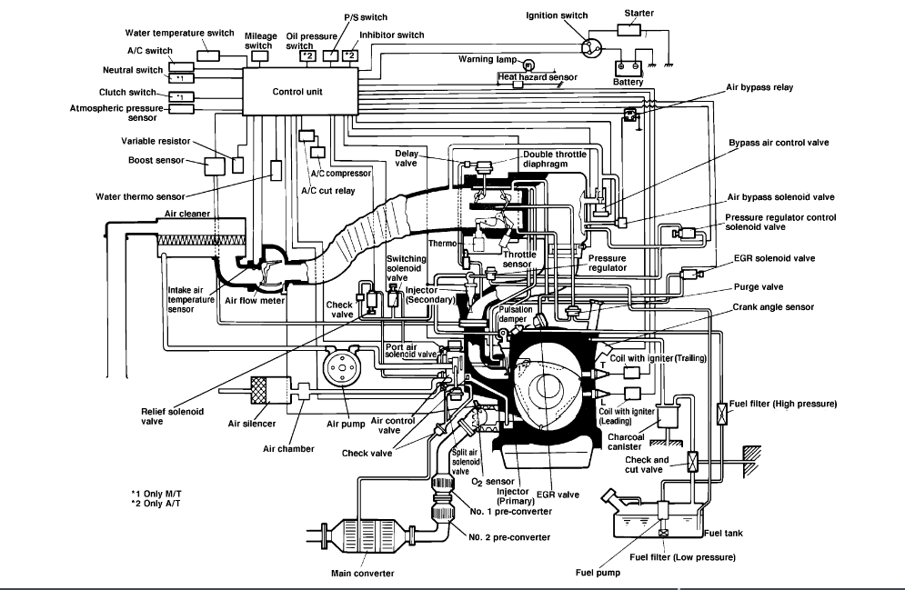
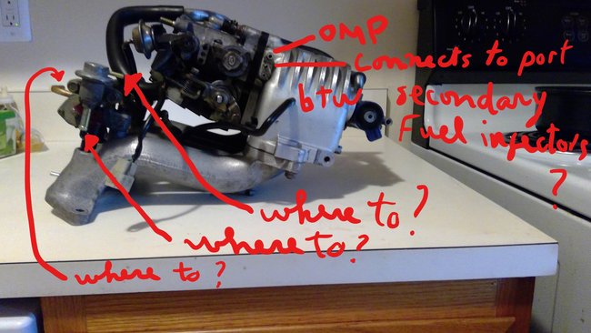
I removed the UIM in order to do some work under it. It's been some time and I'm trying to remember where each hose goes. There is a nipple on top of engine block, If I connect a hose on that nipple where would i connect the other end? Or could I just cap it? Question 2: i forgot where the cruise control unit, which is located on passenger's side near firewall, gets its vacuum source( the hose is supposed to go from that unit toward UIM or maybe under it.
Question 3: there is supposed to be a connection between the headers and the actuator pipe to make the actuators work for fifth and sixth port. Help to make that connection is appreciated (location and what it looks like, the actuator pipe).
Sep 12, 2019 at 7:08 AM
Advertisement
Avatar
MASTERWRENCH
  • CERTIFIED EXPERT
  • 258 POSTS
Good morning.

Attached below are the complete vacuum hose routing diagrams for your vehicle. One is for turbo engines (the bigger diagram) and the other is non-turbo. Hopefully this gives you a better idea where every thing connects.

Let me know if you need anything else!
Sep 12, 2019 at 7:25 AM
Avatar
REDBUG
  • MEMBER
  • 6 POSTS
Not helpful. The images do not answer my questions.
Sep 12, 2019 at 12:42 PM
Advertisement
Avatar
STRAILER
  • CERTIFIED EXPERT
  • 53,854 POSTS
I checked out the answer looks good. what else are you looking for?
Sep 12, 2019 at 12:43 PM
Avatar
REDBUG
  • MEMBER
  • 6 POSTS
Those diagrams do not show the top of engine where the vacuum spout is located. I wanted to know where this spout connects to or whether it can be closed with a cap. Furthermore, the cruise control unit is not shown in the diagrams.
Sep 12, 2019 at 1:08 PM
Avatar
STRAILER
  • CERTIFIED EXPERT
  • 53,854 POSTS
Can you please shoot a quick video with your phone so we can see what's going on? that would be great. You can upload it here with your response.
Sep 13, 2019 at 10:06 AM
Avatar
REDBUG
  • MEMBER
  • 6 POSTS
Can someone provide instructions or photos on my previous question? The FSM diagram or AllData diagram etc., are unhelpful.
Sep 13, 2019 at 4:01 PM (Merged)
Avatar
SCGRANTURISMO
  • CERTIFIED EXPERT
  • 4,897 POSTS
Hello again,

The information that you requested is in the diagrams down below. Please go through these guides and get back to us with what you are able to find out.

Thanks,
Alex
2CarPros
Sep 13, 2019 at 4:01 PM (Merged)
Avatar
REDBUG
  • MEMBER
  • 6 POSTS
Hello Ken,
See attached photo showing the port( looks like a vacuum nipple). It is in between the 2 fuel injectors. Where does this port connect to using a hose? Thanks
Sep 14, 2019 at 9:13 PM
Avatar
STRAILER
  • CERTIFIED EXPERT
  • 53,854 POSTS
Good job on the pic, If you look at the second vacuum diagrams it shows it going to one of the control solenoids
Sep 16, 2019 at 10:30 AM
Avatar
REDBUG
  • MEMBER
  • 6 POSTS
Hello Ken
Following up on the quest about the port in between the 2 fuel injectors. I think it connect to the middle port of the 3ports as shown in the attached pic. Correct me? The hose that's seen hanging, I say it goes to the bottom port of the 3 ports as shown in pic. Can you help with the other arrows with question marks in the pic? 2 are from pulsation damper (?) THANKS
Sep 16, 2019 at 3:07 PM
Avatar
REDBUG
  • MEMBER
  • 6 POSTS
I took care of the brass port question. Answer to the remaing questions is appreciated.
Sep 16, 2019 at 4:27 PM
Avatar
STRAILER
  • CERTIFIED EXPERT
  • 53,854 POSTS
Please post your new question here, you must be logged in.

https://www.2carpros.com/questions/new

Cheers, Ken
Sep 20, 2019 at 9:11 AM