Welcome to 2CarPros.
Here are the directions for removal and replacement of the turbo. I am including all pics which relate to the procedure. They show all lines and hoses.
_______________________________________________________
TURBOCHARGER / EXHAUST MANIFOLD
REMOVAL
CAUTION: IF TURBOCHARGER IS REPLACED DUE TO A BEARING FAILURE, REPLACEMENT OF THE OIL PRESSURE FEED LINE IS REQUIRED. OIL RETURN TUBE SHOULD BE CLEANED ALSO.
NOTE: The turbocharger and exhaust manifold are serviced as an assembly. Do Not attempt to remove the turbocharger from the exhaust manifold. Exhaust leaks will result. It is recommended that the turbocharger elbow be replaced along with the turbochargerlexhaust manifold assembly.
1. Disconnect negative battery cable.
2. Drain cooling system.
3. Remove air cleaner housing and lid.
pic 1
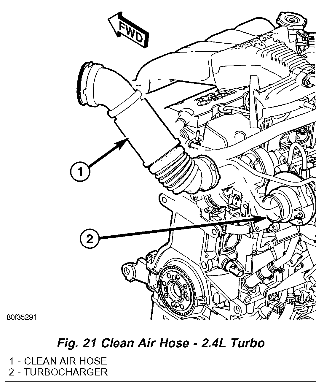
4. Disconnect clean air hose from turbocharger (Fig. 21).
5. Disconnect throttle and speed control cables at throttle body.
6. Disconnect electrical connectors from the following components:
^ Inlet Air Temperature (IAT) Sensor
^ MAP Sensor
^ IAC Motor
^ Throttle Position Sensor
^ Ignition Coil Capacitor
^ Upstream Oxygen Sensor
pic 2
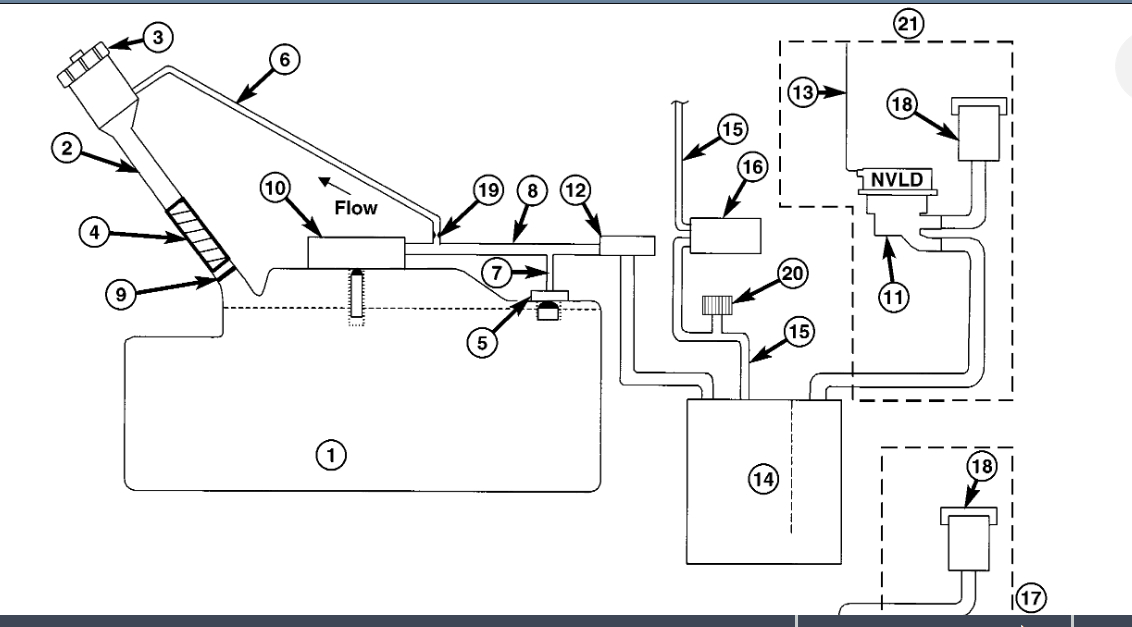
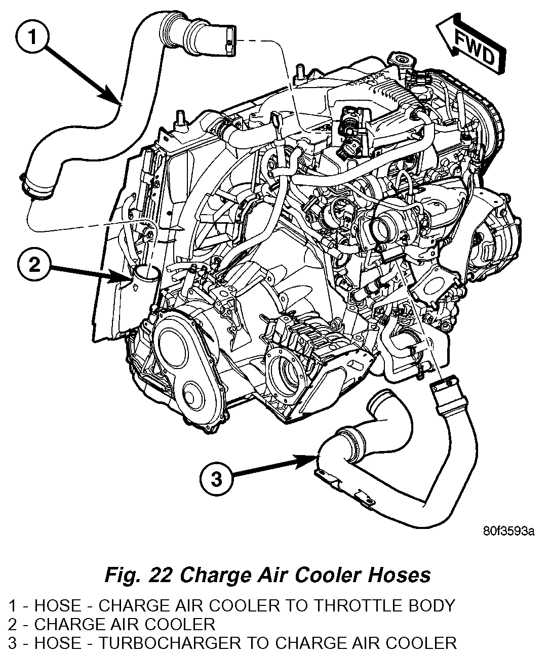
7. Disconnect air inlet hose at throttle body (Fig. 22).
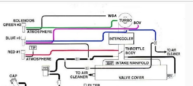
8. Disconnect vacuum hoses at throttle body and upper intake manifold.
pic 3
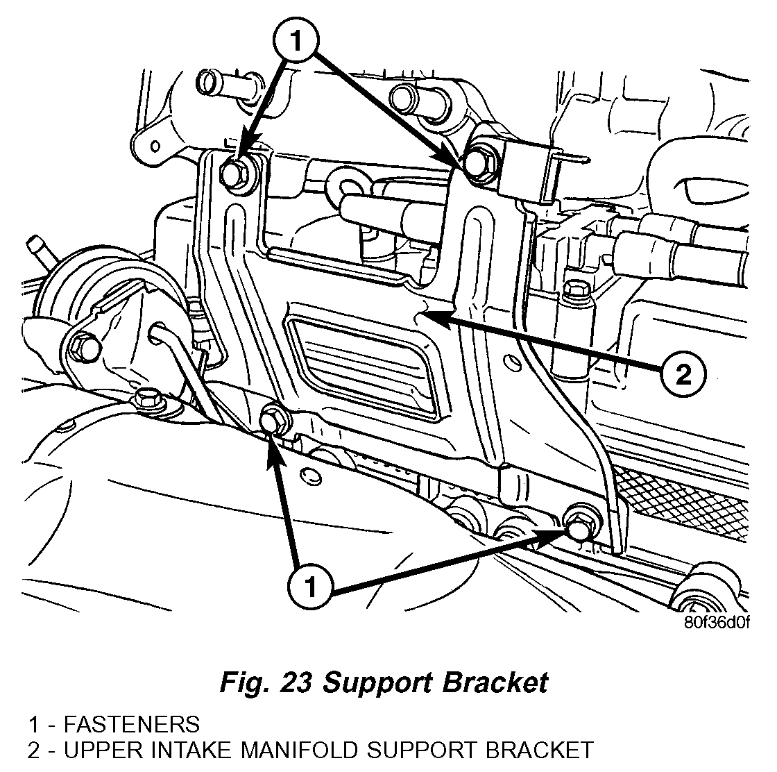
9. Remove upper intake manifold support bracket (Fig. 23).
10. Remove upper intake manifold.
CAUTION: Cover lower intake manifold opening with suitable cover to prevent any foreign objects from entering.
pic 4
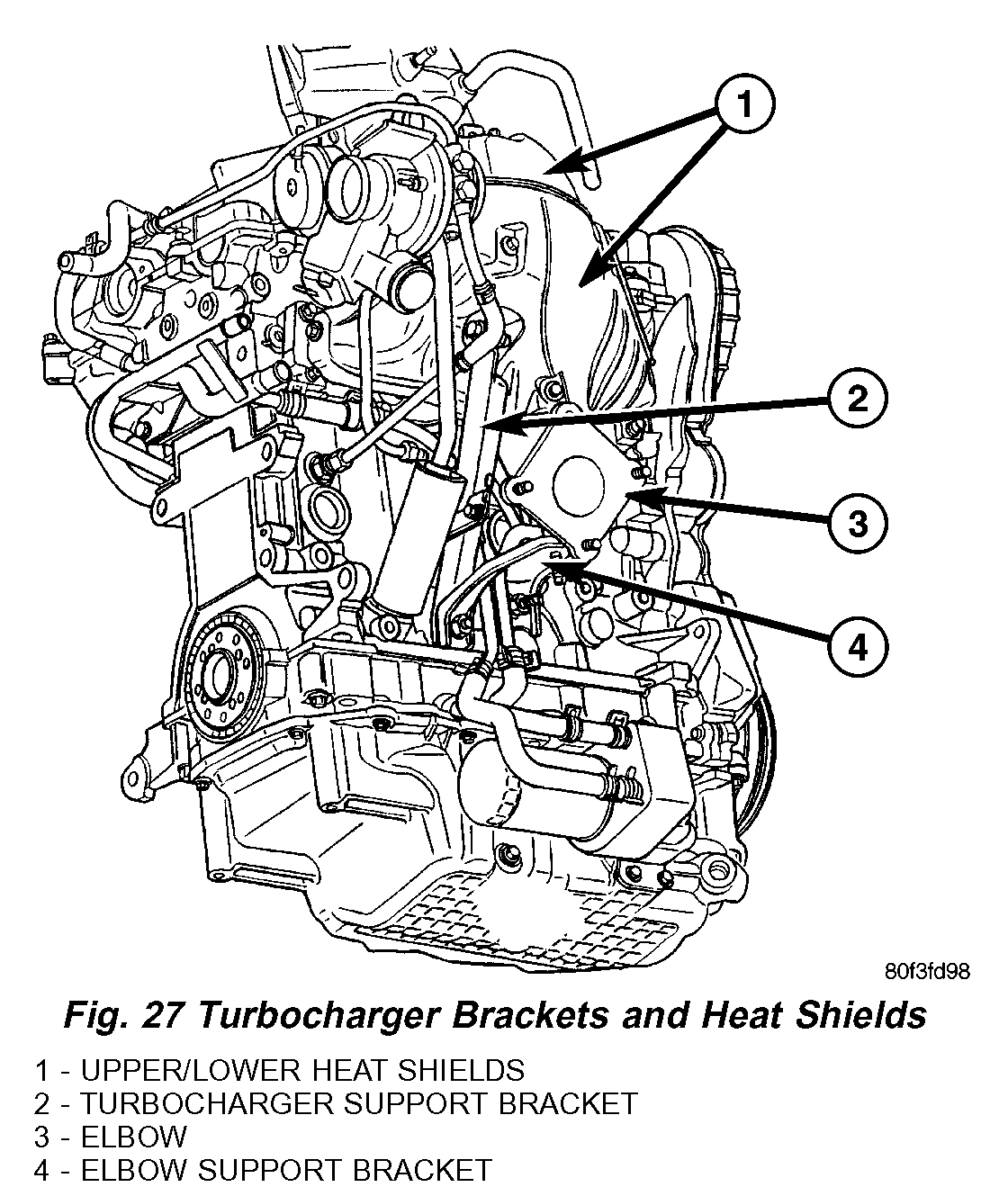
11. Remove turbocharger upper heat shield (Fig. 27).
pic 5
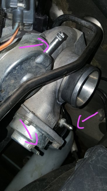
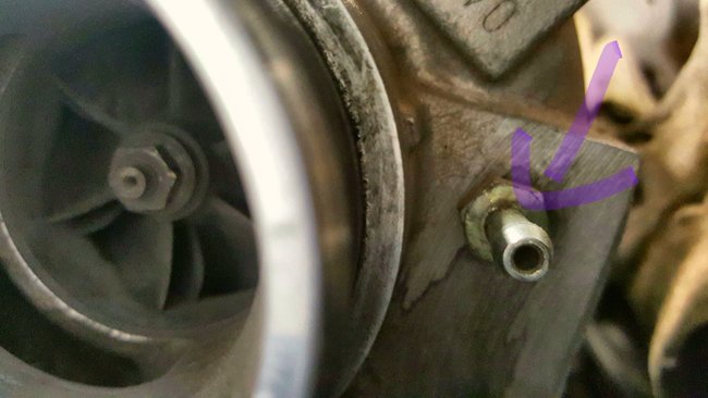
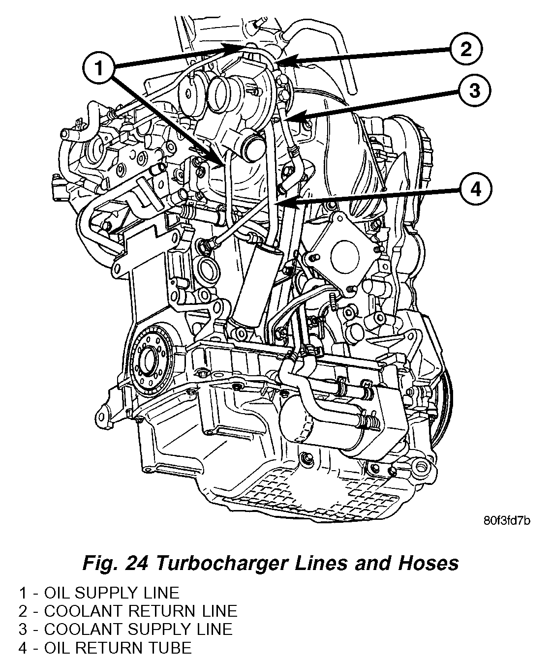
12. Disconnect oil supply line at turbocharger (Fig. 24).
13. Remove coolant return line (Fig. 24).
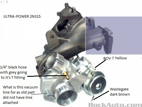
14. Disconnect vacuum hoses from turbocharger.
15. Raise vehicle on hoist.
16. Disconnect muffler ground strap. Remove muffler.
17. Disconnect downstream oxygen sensor.
pic 6
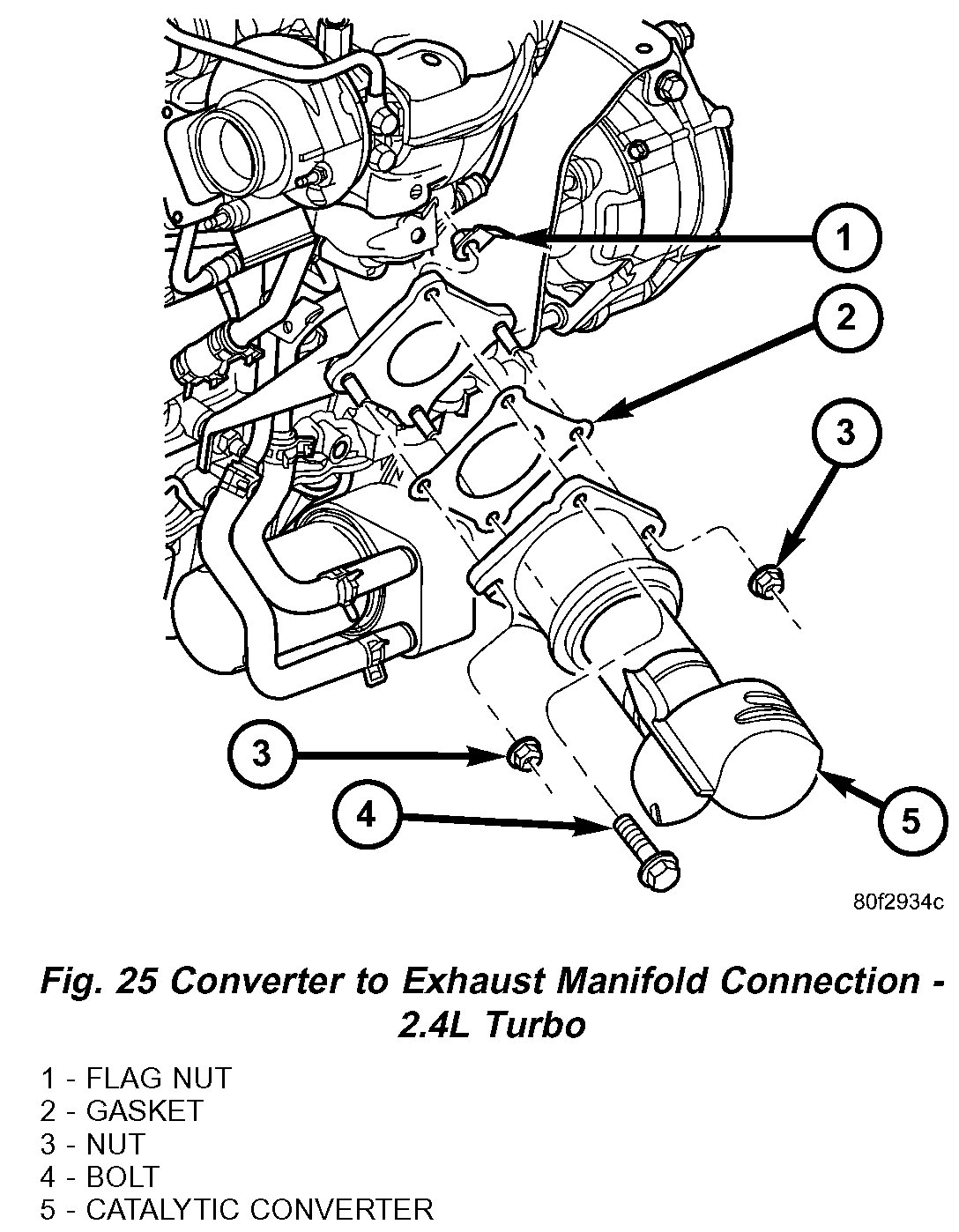
18. Remove fasteners securing catalytic converter to exhaust manifold (Fig. 25).
19. Remove catalytic converter and intermediate pipe as an assembly.
pic 7
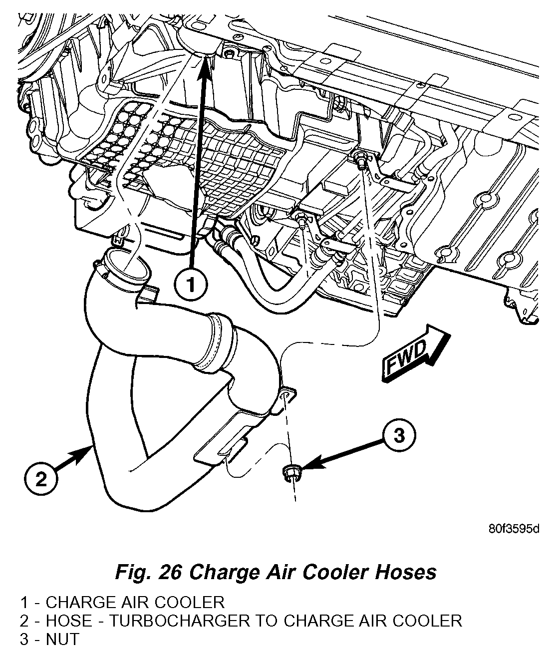
20. Remove turbocharger to charge air cooler hose assembly (Fig. 26).
21. Remove turbocharger elbow support bracket (Fig. 27).
22. Remove turbocharger support bracket (Fig. 27).
23. Remove oil return tube (Fig. 24).
24. Remove turbocharger coolant supply line (Fig. 24).
25. Remove turbocharger lower heat shield (Fig. 27).
26. Remove turbocharger elbow (Fig. 27).
27. Remove lower exhaust manifold fasteners that are accessible while vehicle is on hoist.
28. Lower vehicle.
29. Remove upper exhaust manifold fasteners.
30. Remove turbocharger/exhaust manifold assembly from above/between the engine and cowl panel.
31. Remove and discard exhaust manifold gasket.
INSTALLATION
CAUTION: IF TURBOCHARGER IS REPLACED DUE TO A BEARING FAILURE, REPLACEMENT OF THE OIL PRESSURE FEED LINE IS REQUIRED. OIL RETURN TUBE SHOULD BE CLEANED ALSO.
NOTE: The turbocharger and exhaust manifold are serviced as an assembly. Do Not attempt to remove the turbocharger from the exhaust manifold. Exhaust leaks will result. It is recommended that the turbocharger elbow be replaced along with the turbochargerlexhaust manifold assembly.
1. Clean gasket sealing surfaces. Replace exhaust manifold gasket. DO NOT APPLY SEALER TO GASKET.
NOTE: Stainless steel layer of exhaust manifold gasket goes against cylinder head, graphite layer of gasket goes against manifold surface.
2. Turbocharger/exhaust manifold assembly is installed from above/between the engine and cowl panel.
pic 8
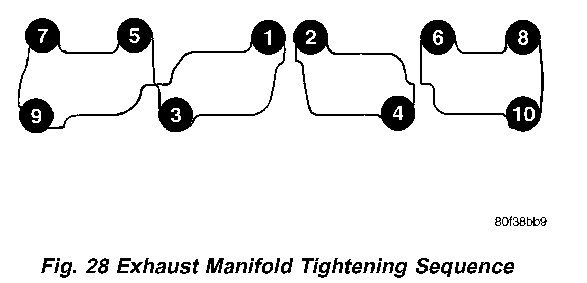
3. Position turbocharger/exhaust manifold assembly in place. Gradually tighten fasteners, starting at center and progressing outward in both directions to 28 Nm (250 in. lbs.) (Fig. 28). Raise and lower vehicle for fastener access as necessary Repeat tightening procedure until all fasteners are at specified torque.
4. Install turbocharger elbow. Torque fasteners to 28 Nm (250 in. lbs.) (Fig. 27).
5. Install turbocharger lower heat shield. Torque fasteners to 28 Nm (250 in. lbs.) (Fig. 27).
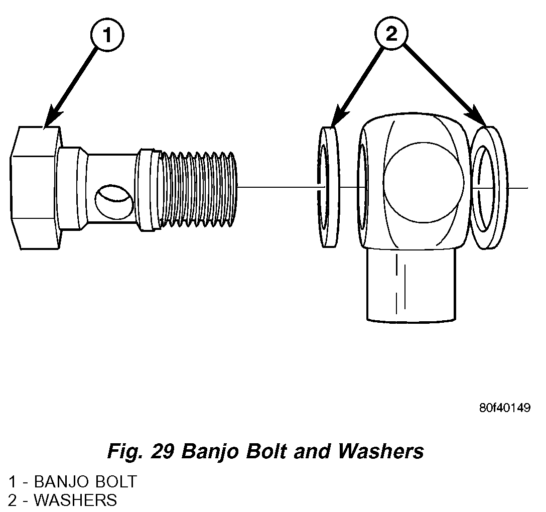
6. Install turbocharger coolant supply line. Install NEW washers (Fig. 29). Torque banjo fitting bolt to 30 Nm (22 ft. lbs.). Torque flared fitting to 31 Nm (23 ft. lbs.) (Fig. 24).
7. Replace oil return tube gasket. Install oil return tube. Torque fasteners to 12 Nm (105 in. lbs.). Make sure heat shield for oil return line is properly installed (Fig. 24).
8. Install turbocharger support bracket. Torque M8 fasteners to 28 Nm (250 in. lbs.) and M10 fasteners to 54 Nm (40 ft. lbs.) (Fig. 27).
9. Install turbocharger elbow support bracket (Fig. 27).
10. Install turbocharger to charge air cooler hose assembly (Fig. 26).
11. Install catalytic converter and intermediate pipe as an assembly.
12. Install fasteners securing catalytic converter to exhaust manifold (Fig. 25). Torque fasteners to 28 Nm (250 in. lbs.).
13. Install muffler. Connect muffler ground strap.
14. Connect downstream oxygen sensor.
15. Lower vehicle.
16. Connect vacuum hoses to turbocharger.
pic 9
17. Install coolant return line. Install NEW washers (Fig. 29). Torque banjo fitting bolt to 30 Nm (22 ft. lbs.) (Fig. 24).
18. Connect oil supply line at turbocharger. Torque flared fitting to 31 Nm (23 ft. lbs.) (Fig. 24).
19. Install turbocharger upper heat shield. Torque fasteners to 28 Nm (250 in. lbs.) (Fig. 27).
20. Install upper intake manifold.
21. Install upper intake manifold sup port bracket (Fig. 23).
22. Connect vacuum hoses at throttle body and upper intake manifold.
23. Connect air inlet hose at throttle body (Fig. 22).
24. Connect electrical connectors to the following components:
^ Inlet Air Temperature (IAT) Sensor
^ MAP Sensor
^ IAC Motor
^ Throttle Position Sensor
^ Ignition Coil Capacitor
^ Upstream Oxygen Sensor
25. Connect throttle and speed control cables at throttle body
26. Connect clean air hose to turbocharger (Fig. 21).
27. Install air cleaner housing and lid.
28. Fill cooling system.
29. Change oil and filter.
30. Connect negative battery cable.
___________________________________
Please let me know if this helps or if you have other questions.
Take care,
Joe
Images (Click to enlarge)
Jan 25, 2021 at 1:36 PM
(Merged)