Hi and thanks for using 2carpros.com
If you count all of them, there are 7 related to shifting. However, there are 4 specific to the actual sift.
Here are the directions for installing them. The attached pictures correlate with them. You will note that three of them indicate something other than shift. Here are what they do.
SLN is the accumulator back pressure solenoid. It allows for a smooth shift.
SLU is for torque converter lock up
SLT controls internal line pressure to maintain smooth operation.
Here are the directions for replacement. The attached pictures correlate with these directions and indicate what each solenoid valve does.
ON-VEHICLE REPAIR
ON-VEHICLE REPAIR
CAUTION: When working with FIPG material, you must observe the following items.
- Using a razor blade and gasket scraper, remove all the old FIPG material from the gasket surfaces.
- Thoroughly clean all components to remove all the loose material.
- Clean both sealing surfaces with a non-residue solvent.
- Apply FIPG in an approx. 1 mm (0.04 inch) wide bead along the sealing surface.
- Parts must be assembled within 10 minutes of application. Otherwise, the FIPG material must be removed and reapplied.
1. REMOVE DRAIN PLUG WITH GASKET AND DRAINAGE
2. REMOVE OIL PAN. Refer to Temperature Sensor, Transmission Control; Service and Repair.
3. EXAMINE PARTICLES IN PAN
4. REMOVE OIL STRAINER
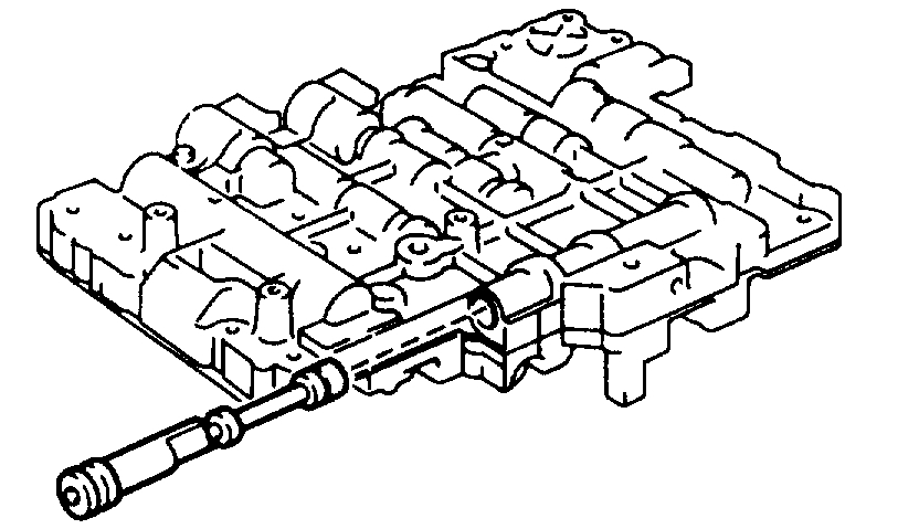
5. REMOVE SOLENOID WIRING WITH ATF TEMPERATURE SENSOR
Pic 1
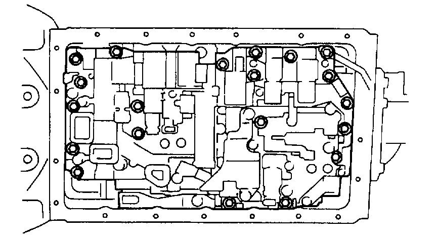
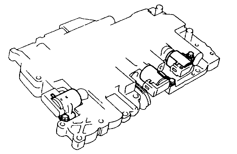
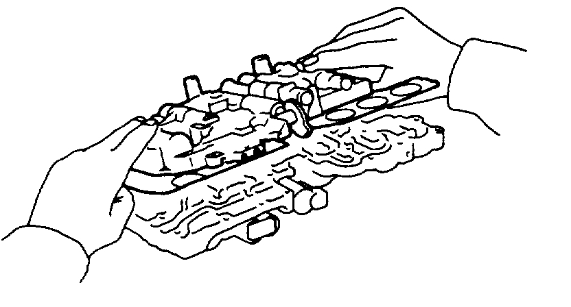
6. REMOVE VALVE BODY
a. Remove the 21 bolts and valve body.
Pic 2
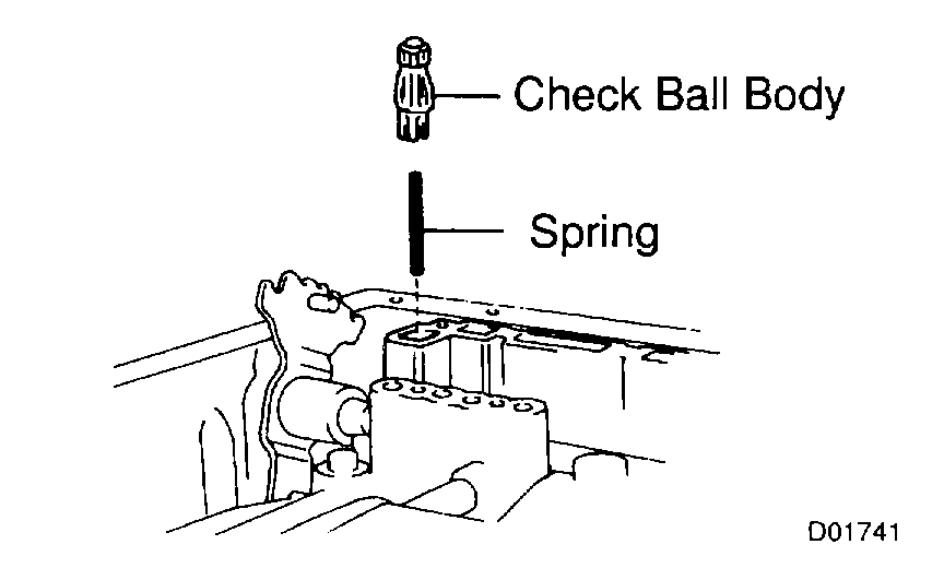
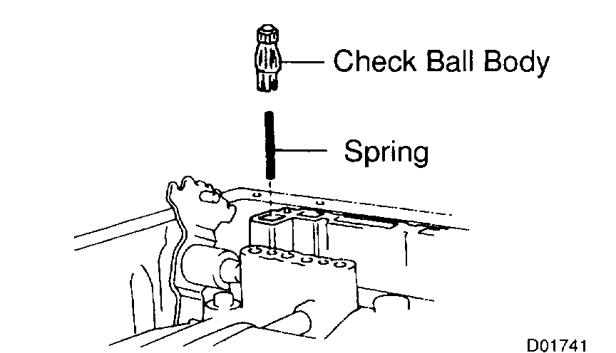
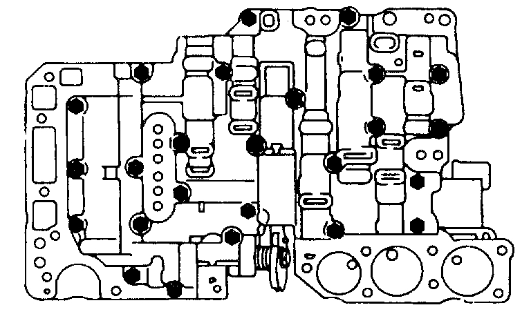
7. REMOVE CHECK BALL BODY AND SPRING
NOTICE: Do not drop the check ball body and spring.
Pic 3
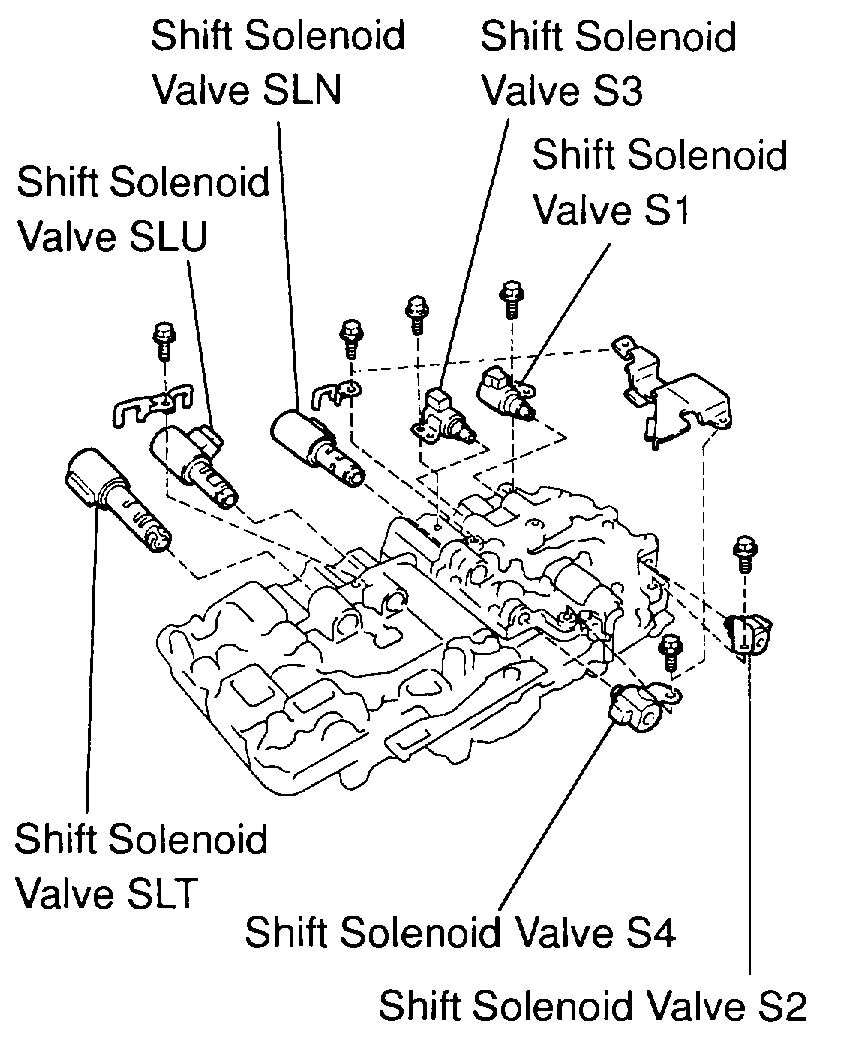
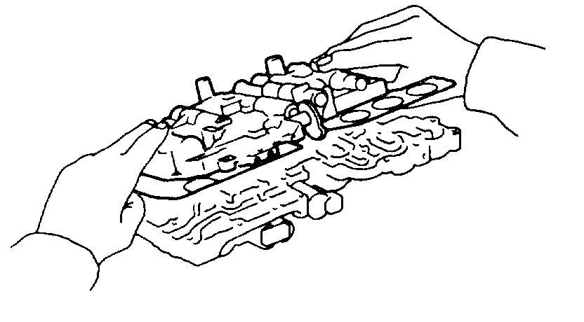
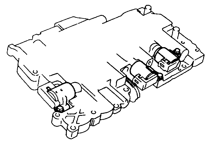
8. REMOVE SOLENOID VALVE
a. Remove the 3 bolts and shift solenoid valve No.1, No.2 and No.3.
b. Remove the 2 bolts, oil guide plate, lock plate, shift solenoid valve SLN and No.4.
c. Remove the 6 O-rings from each shift solenoid valve.
d. Remove the bolt, lock plate and shift solenoid valve SLU and SLT.
9. INSTALL SOLENOID VALVE
a. Install the shift solenoid valve SLU and SLT and the lock plate with the bolt.
Torque: 6.4 Nm (65 kgf-cm, 56 inch lbs.)
b. Coat 6 new O-rings with ATF.
c. Install the 6 O-rings to the each solenoid valve.
d. Install the shift solenoid valve SLN, No.4, lock plate and oil guide plate with the 2 bolts.
Torque: 10 Nm (100 kgf-cm, 7 ft. lbs.)
e. Install the shift solenoid valve No.1, No.2 and No.3 with the 3 bolts.
Torque:
Shift solenoid valve No.1 and No.3:
6.4 Nm (65 kgf-cm, 56 inch lbs.)
Shift solenoid valve No.2:
10 Nm (100 kgf-cm, 7 ft. lbs.)
Pic 4
10. INSTALL CHECK BALL BODY AND SPRING
11. INSTALL VALVE BODY
Pic 5
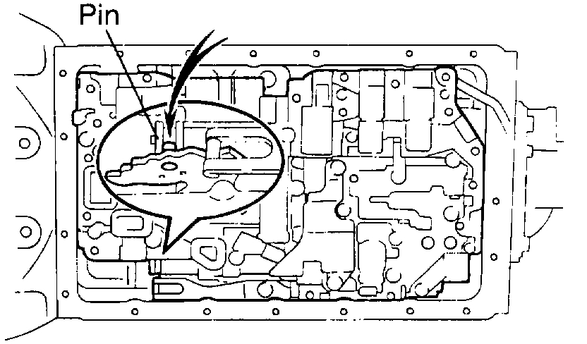
a. Align the groove of the manual valve to pin of the lever.
Pic 6
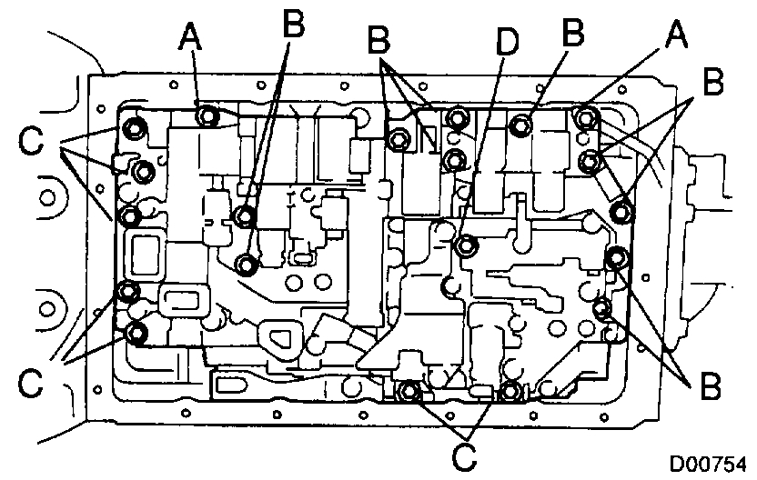
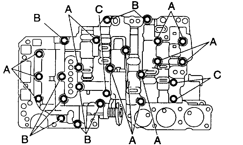
b. Install the 21 bolts.
Torque: 10 Nm (100 kgf-cm, 7 ft. lbs.)
Bolt length:
Bolt A: 23 mm (0.91 inch)
Bolt B: 28 mm (1.10 inch)
Bolt C: 36 mm (1.42 inch)
Bolt D: 55 mm (2.17 inch)
12. INSTALL SOLENOID WIRING WITH ATF TEMPERATURE SENSOR
13. INSTALL OIL STRAINER
14. INSTALL OIL PAN
15. INSTALL DRAIN PLUG WITH NEW GASKET
Torque: 20 Nm (205 kgf-cm, 15 ft. lbs.)
16. FILL FLUID AND CHECK FLUID
_________________________________________
Okay, with that being said, you said shift solenoid C is the problem. C is the SLU solenoid. It is responsible for converter lock up. If you are experiencing converter lock up when the lock up system is off, or it remains off when the unit is on, this is the most likely cause. However, it can also be related to contamination or dirt in the valve body or the torque converter lock up clutch has failed.
If those are the symptoms you are experiencing, you could get away with just the one solenoid. However, if the fluid was never changed and dirt is an issue, you should replace all and I would suggest taking apart the valve body and cleaning and inspecting it.
Here are the directions for valve body disassembly. I'm adding them just in case you need them. Starting with picture 6, the remaining pics correlate with these directions. If you do this, it must go back together exactly the same way it was taken apart.
_________________________________________
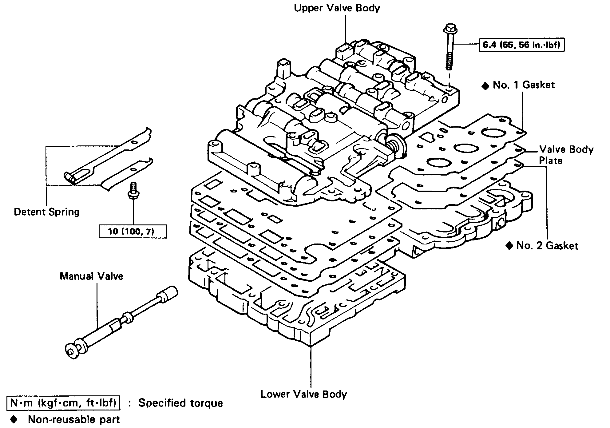
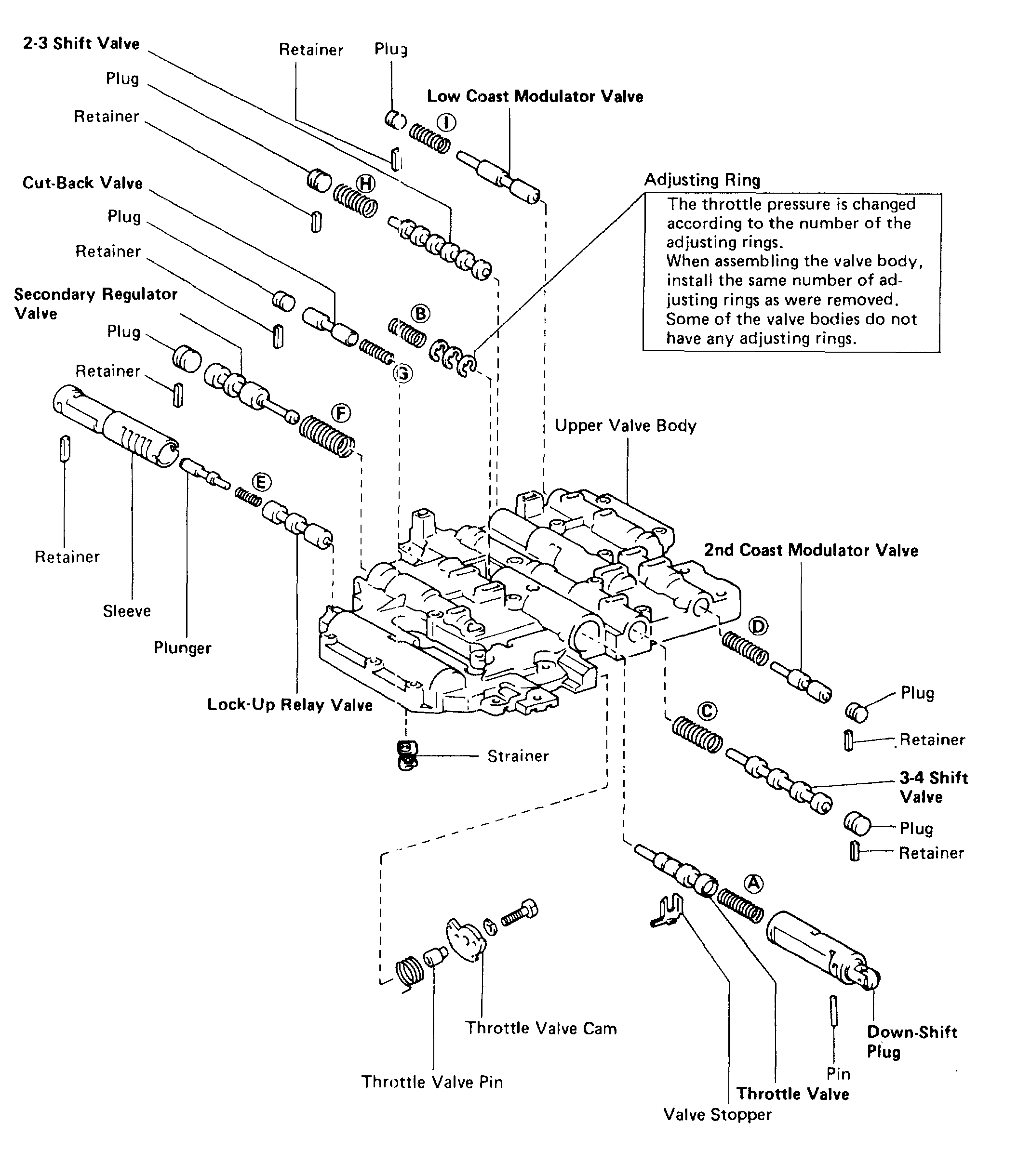
VALVE BODY
COMPONENTS
Pic 7
VALVE BODY DISASSEMBLY
Pic 8
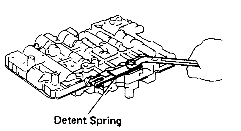
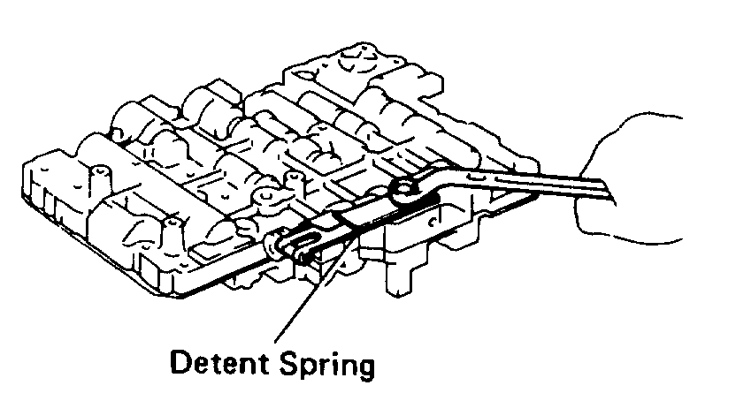
1. UNBOLT AND REMOVE DETENT SPRING
Pic 9
2. REMOVE MANUAL VALVE
Pic 10
3. REMOVE 3 SOLENOIDS
Pic 11
4. TURN OVER ASSEMBLY AND REMOVE 25 BOLTS
Pic 12
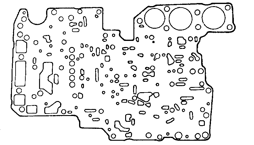
5. LIFT OFF UPPER VALVE BODY AND PLATE AS A SINGLE UNIT
Hold the valve body plate to the upper valve body.
HINT: Be careful that the check balls and strainer do not fall out.
VALVE BODY ASSEMBLY
Pic 13
1. POSITION NEW NO.1 GASKET ON UPPER VALVE BODY
Align a new No.1 gasket at each bolt hole.
2. POSITION VALVE BODY PLATE ON NO.1 GASKET
Align the plate at each bolt hole.
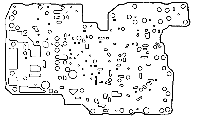
Pic 14
3. POSITION NEW NO.2 GASKET ON PLATE
Align a new No.2 gasket at each bolt hole.
Pic 15
4. PLACE UPPER VALVE BODY WITH PLATE AND GASKETS ON TOP OF LOWER VALVE BODY
Align each bolt hole and gasket in the valve body.
Pic 16
5. INSTALL 25 BOLTS TO UPPER VALVE BODY
HINT: Each bolt length is indicated below.
Torque: 6.4 Nm (65 kgf.cm, 56 inch lbs.)
Bolt length:
Bolt A: 38 mm (1.50 inch)
Bolt B: 20 mm (0.79 inch)
Bolt C: 28 mm (1.10 inch)
Pic 17
6. INSTALL 3 SOLENOIDS
Pic 18
7. INSTALL MANUAL VALVE
8. INSTALL DETENT SPRING
Torque: 10 Nm (100 kgf.cm, 7 ft. lbs.)
9. MAKE SURE MANUAL VALVE MOVES SMOOTHLY
UPPER VALVE BODY
COMPONENTS
Pic 19
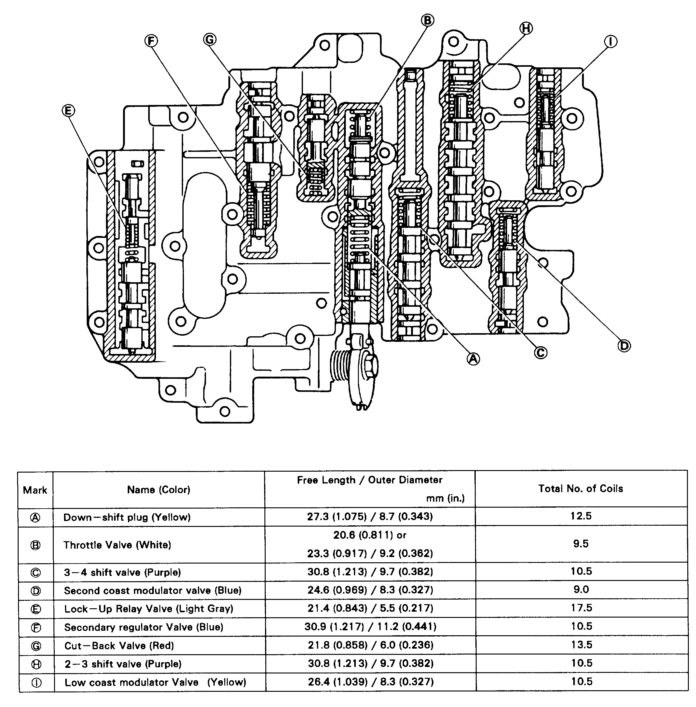
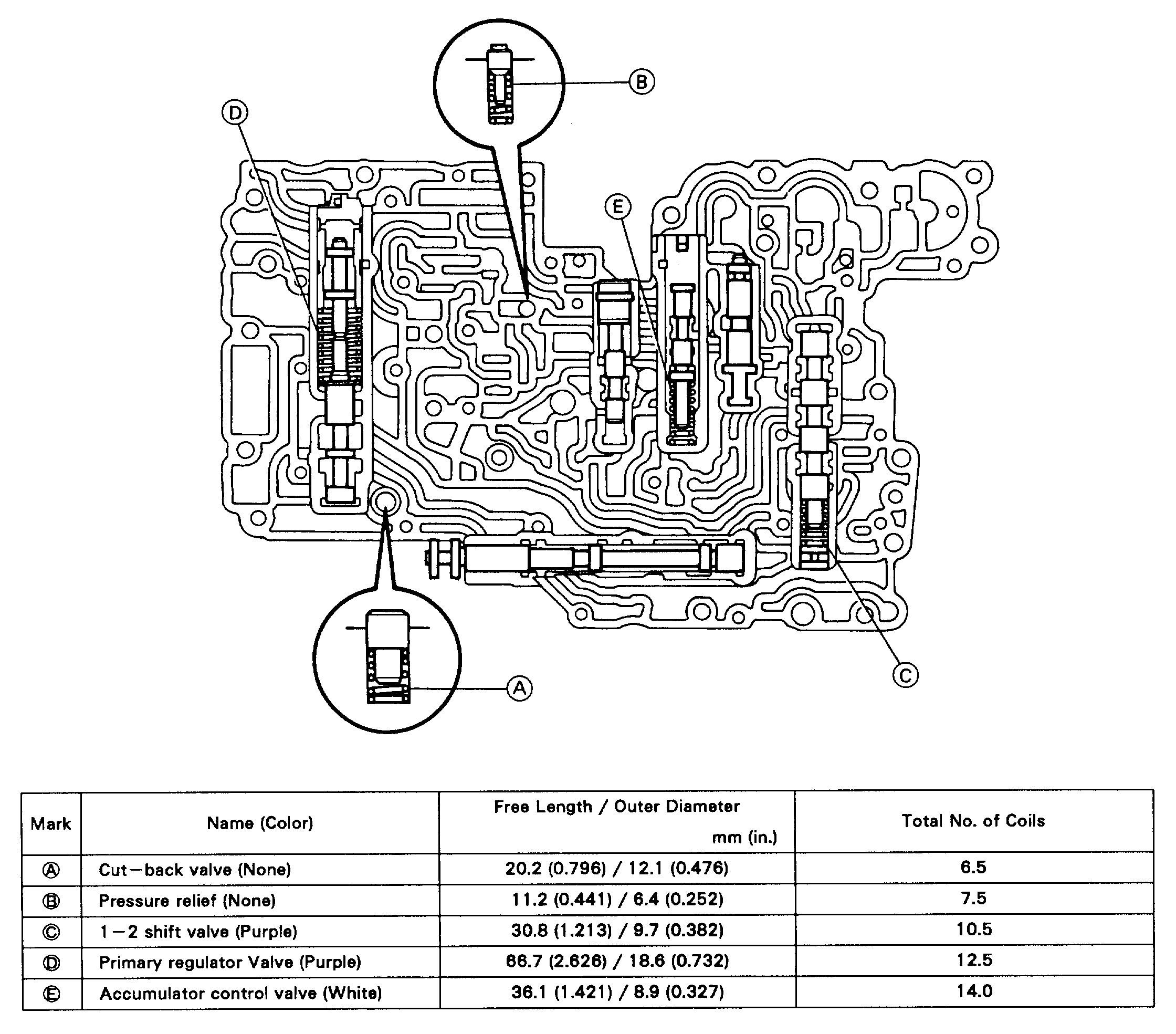
VALVE BODY SPRING SPECIFICATIONS
Pic 20
HINT: During reassembly please refer to the spring specifications below to help differentiate between the different springs.
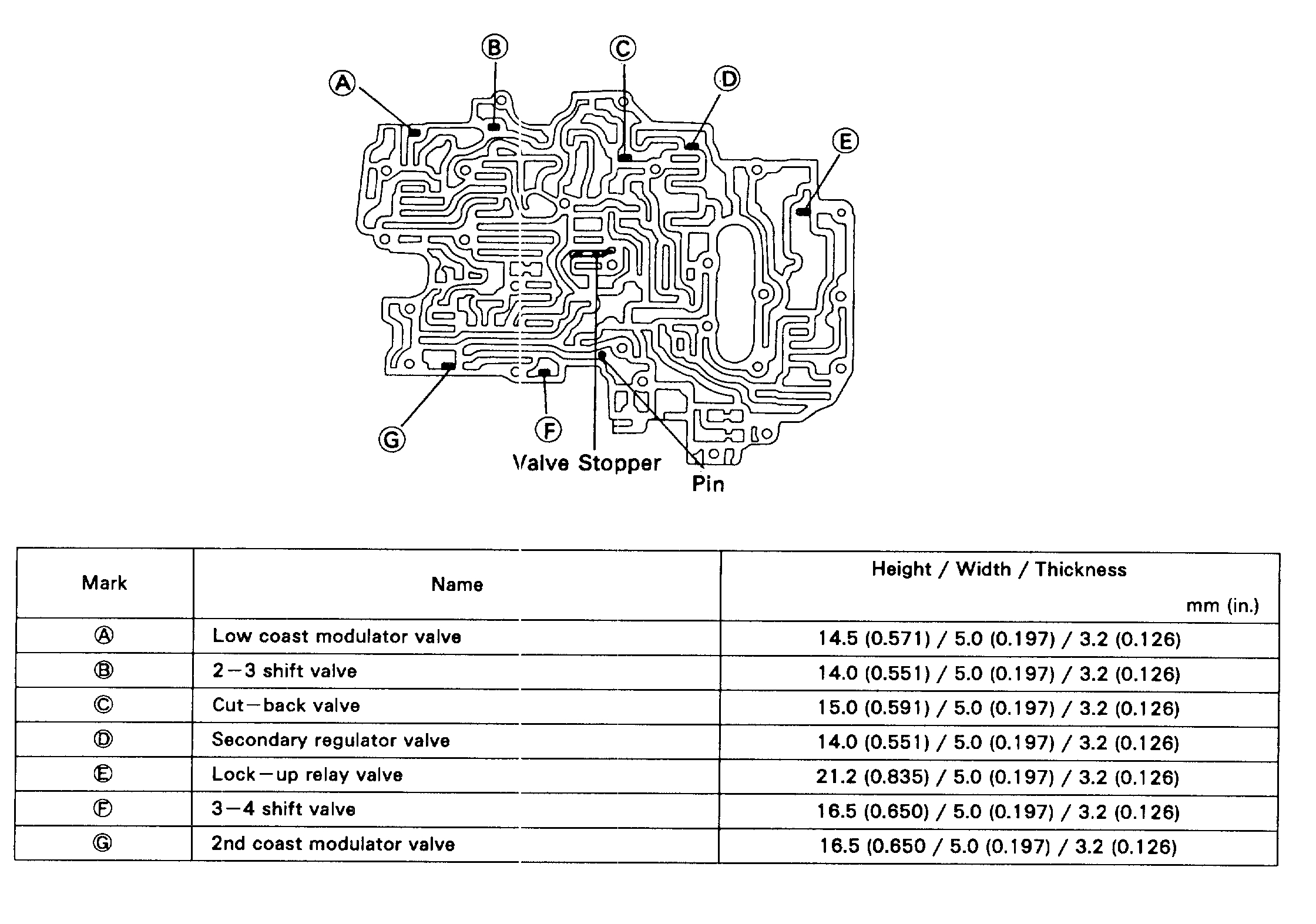
RETAINERS, PIN, STOPPER, CHECK BALLS AND STRAINER LOCATION
Pic 21
1. RETAINER, STOPPER AND PIN
Pic 22
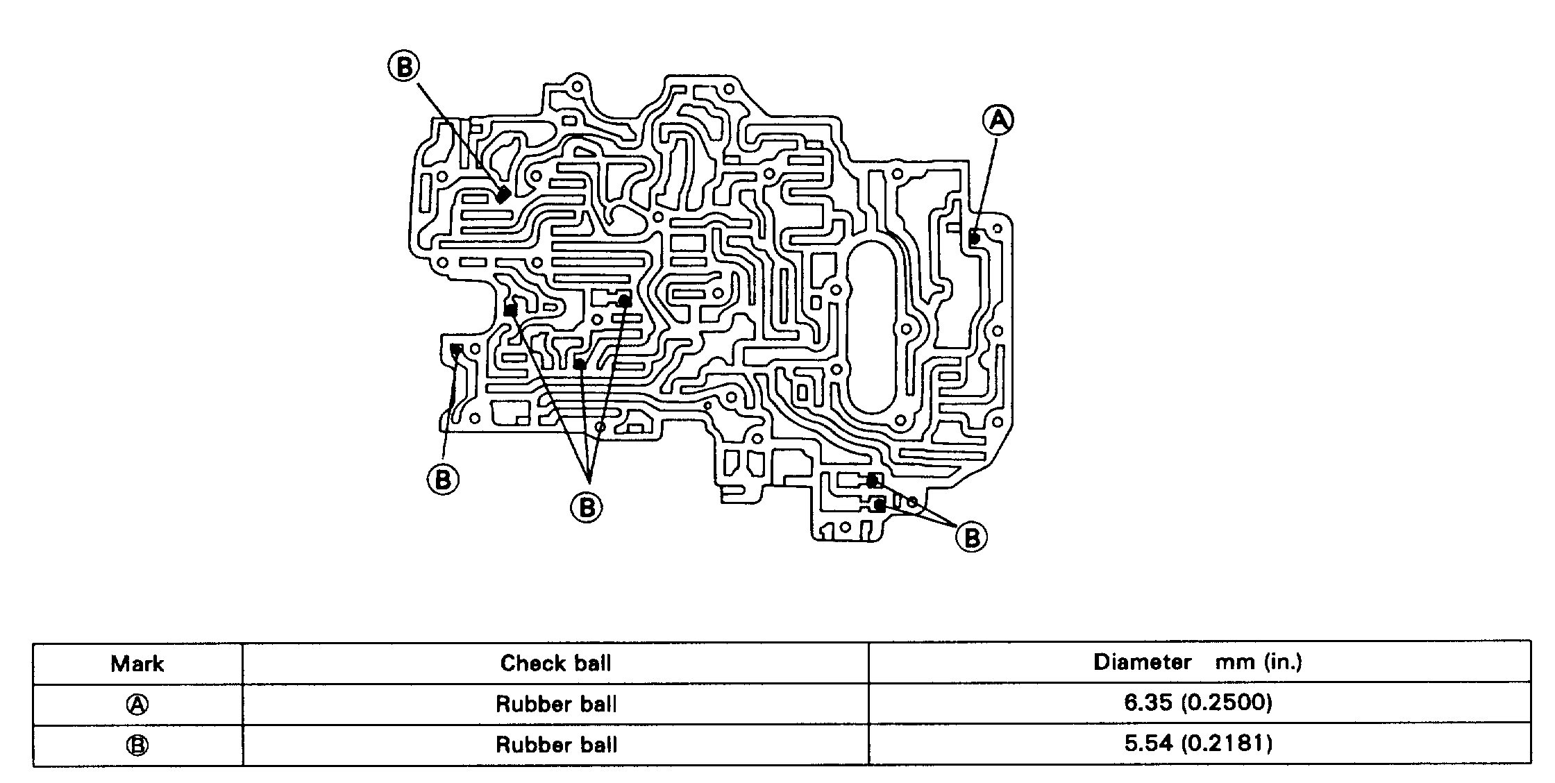
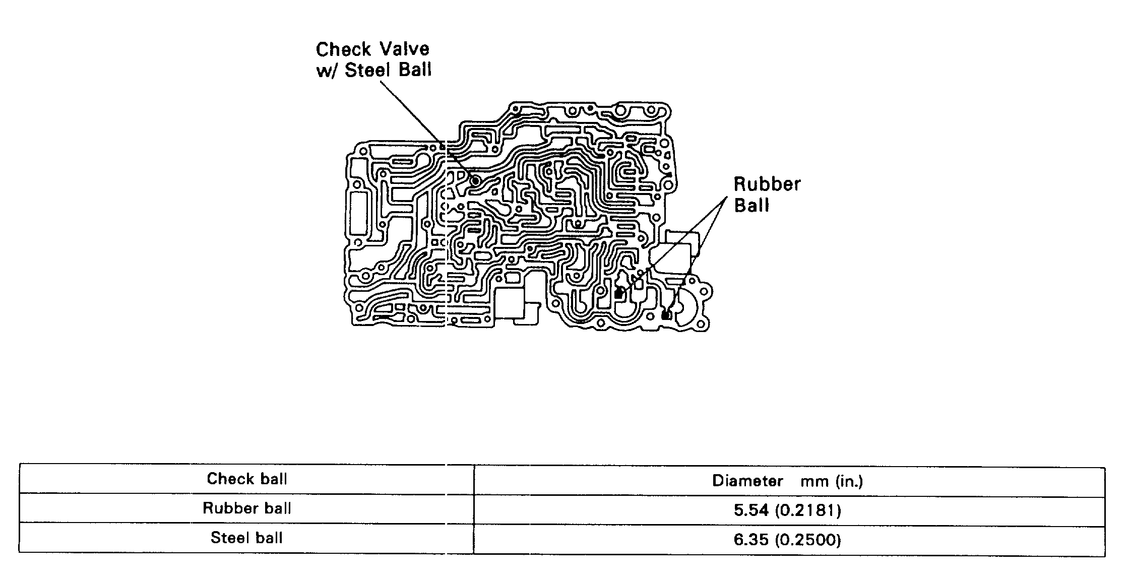
2. CHECK BALL
Pic 23
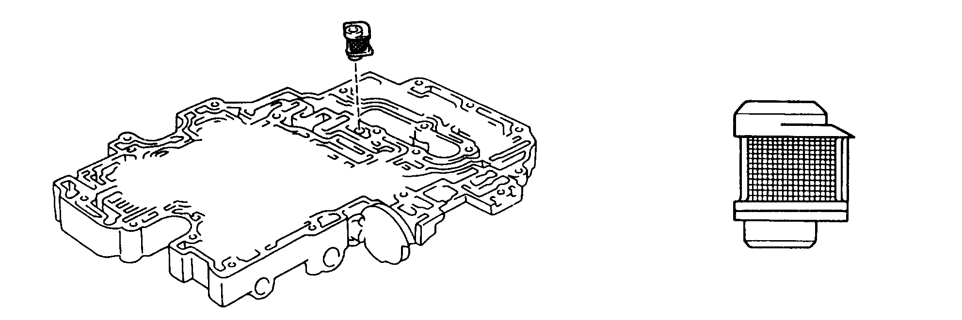
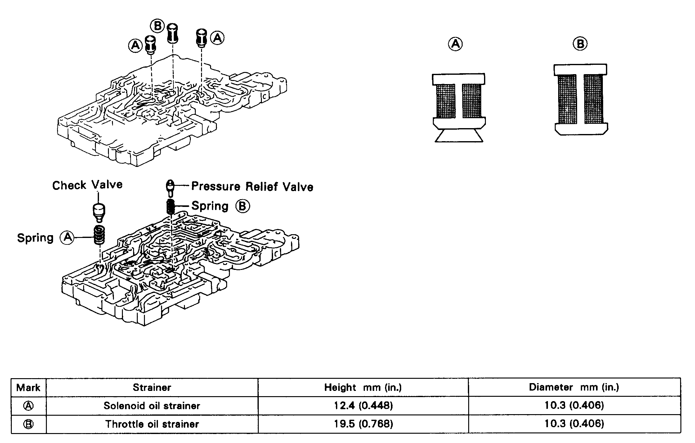
3. STRAINER
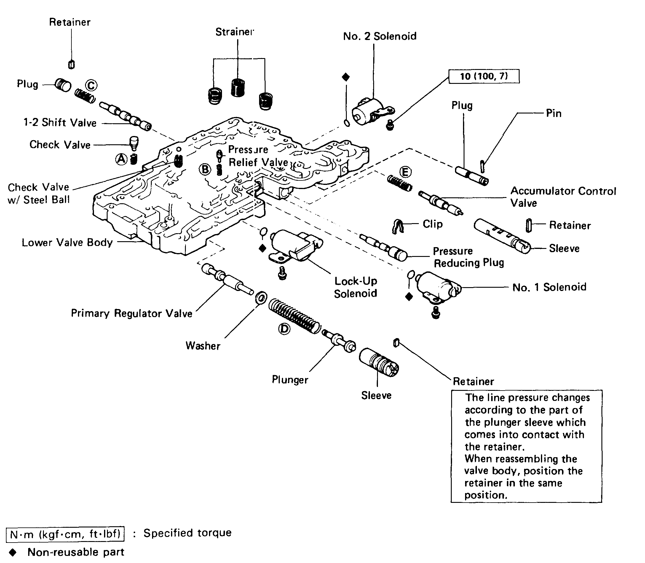
LOWER VALVE BODY
COMPONENTS
Pic 24
VALVE BODY SPRING SPECIFICATIONS
Pic 25
HINT: During reassembly please refer to the spring specifications below to help differentiate between the different springs.
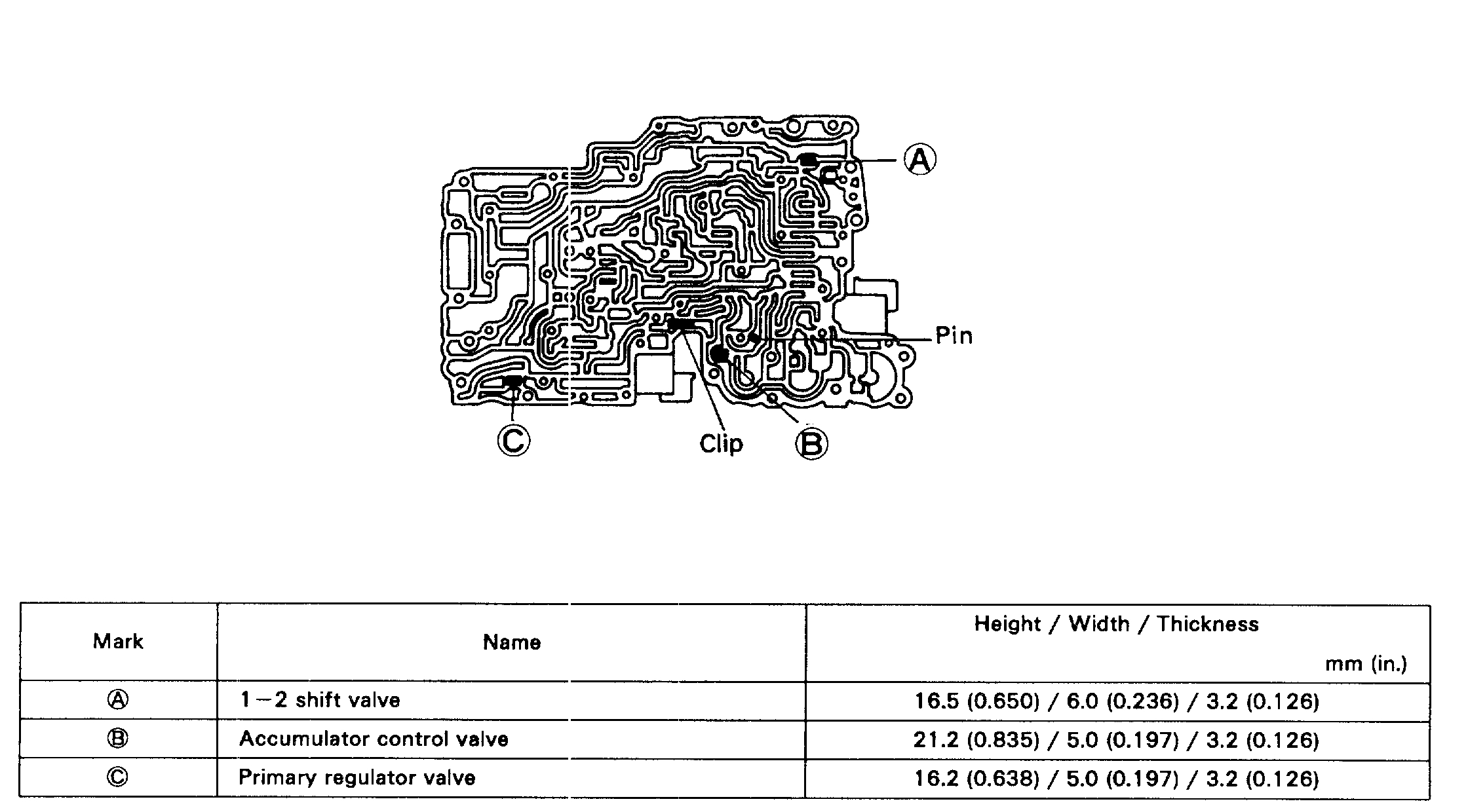
RETAINERS, CLIP, CHECK BALLS, STRAINERS, SPRINGS AND VALVES LOCATION
Pic 26
1. RETAINER AND CLIP
Pic 27
2. CHECK BALL
Pic 28
3. STRAINER, SPRING AND VALVE
_________________________________________
I hope this helps. Let me know if you have questions or just need help.
Take care,
Joe
Images (Click to enlarge)
Jan 27, 2019 at 6:47 PM