Transfer case control module

2006 GMC SIERRA
250,000 MILES • 5.3L • V8 • 4WD • AUTOMATIC
Avatar
BLCKLBRTRVR
  • MEMBER
  • 9 POSTS
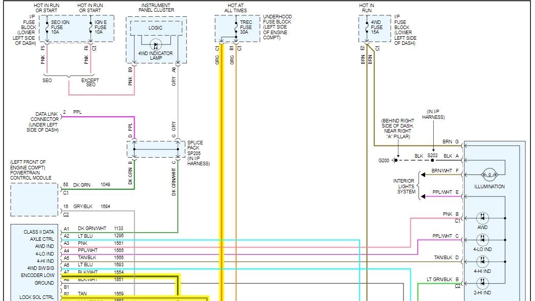
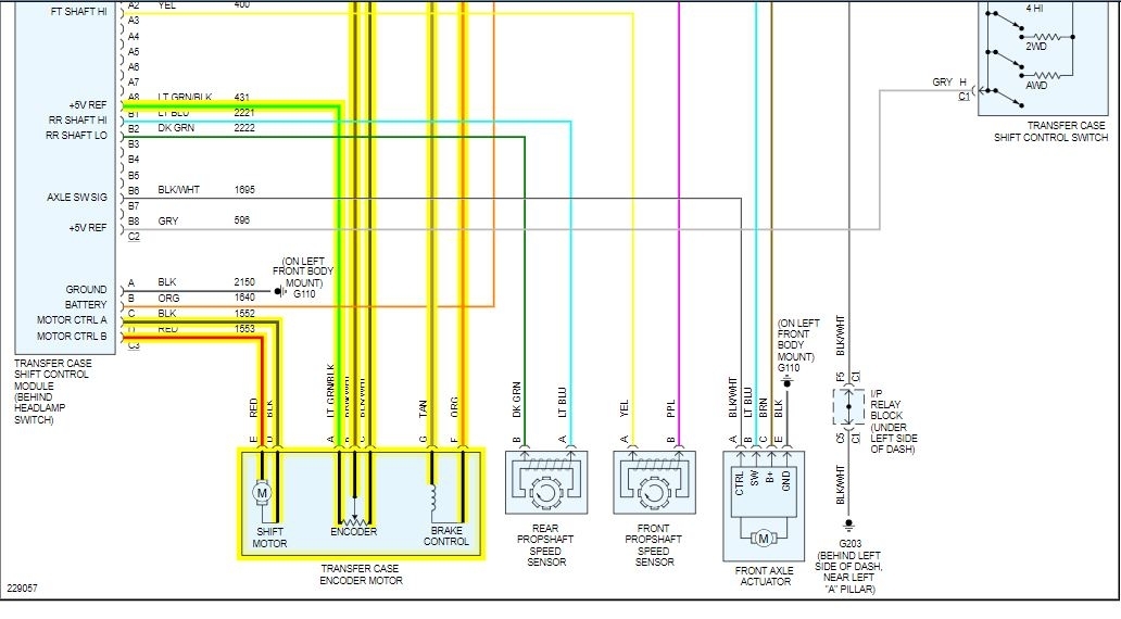
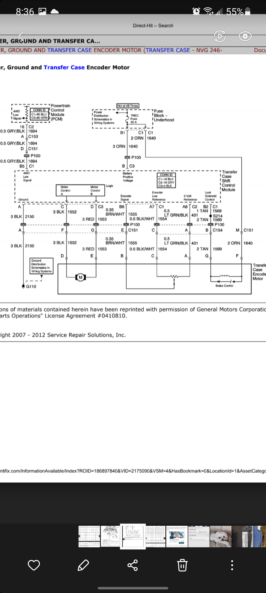
When checking for 5vlt at signal wire (Lt grn/blck + blk/wht)at female end of harness at encoder motor. I don't get a reading until I put one lead to the frame. Same happens when I check return signal with jumper.

I check all wires from module to encoder motor and from engine to module for ohms, nothing over .2. I checked voltage at module I had 5.06 volts at signal wire same as above. I had 12.5 volt for battery.

Do you think the tcc module is bad at the blck/wht (encoder low reference) wirer?
Dec 22, 2020 at 10:46 AM
Advertisement
Avatar
ASEMASTER6371
  • CERTIFIED EXPERT
  • 52,796 POSTS
Good evening,

I attached a wiring diagram for you to view. It is a 3 wire connector. You should have reference voltage on both the reference and the signal wire from the module.

https://www.2carpros.com/articles/how-to-check-wiring

The return wire is the ground controlled by the module.

Can you verify these voltages?

Roy
Dec 22, 2020 at 3:08 PM
Avatar
BLCKLBRTRVR
  • MEMBER
  • 9 POSTS
I had at the module 5.06 volts for signal wire and 5.06 volts for return signal but when I plugged the harness into module and tested from the end of harness near encoder. I get nothing. When i test same wirers from engine side I had 5.06 volts.
Dec 22, 2020 at 6:26 PM
Advertisement
Avatar
BLCKLBRTRVR
  • MEMBER
  • 9 POSTS
If I try to get volt reading from black/white encoder low reference on harness with dvm - an dvm + on 5 volt reference light green/black and same for dvm + brown/white encoder signal I get .1
But I get the right readings for all other wire on harness using dvm - on encoder low reference black/white an dvm + on other wires. So confused.
Dec 22, 2020 at 7:12 PM
Avatar
ASEMASTER6371
  • CERTIFIED EXPERT
  • 52,796 POSTS
Based on your results you need the module.

Roy

Transfer Case Shift Control Module Replacement

Removal Procedure


imageOpen In New TabZoom/Print


1. Disconnect the shift control module electrical connectors.


imageOpen In New TabZoom/Print


2. Unsnap and remove the shift control module from the bracket.

Installation Procedure


imageOpen In New TabZoom/Print


1. If a new control module is being installed, program the new module. Refer to Control Module References in Computer/Integrating Systems. See: Vehicle > Programming and Relearning
2. Install the shift control module to the bracket.


imageOpen In New TabZoom/Print


3. Connect the shift control module electrical connectors.
4. Start the engine and test the automatic transfer case system for proper shift operation.
Dec 23, 2020 at 3:04 AM
Avatar
BLCKLBRTRVR
  • MEMBER
  • 9 POSTS
I tested the module it's okay values are good. But if I reconnect harness and measure at encoder connector female side of harness I'm not getting the right readings from encoder signal, low reference and 5 volt reference. This is where I get on fused. Thinking I need to do a voltage drop test on those three wirers? When I test at connection in engine compartment of same three wire I think coming from module I get correct value.
Dec 23, 2020 at 6:09 AM
Avatar
ASEMASTER6371
  • CERTIFIED EXPERT
  • 52,796 POSTS
How did you test the module?

Roy
Dec 23, 2020 at 6:31 AM
Avatar
BLCKLBRTRVR
  • MEMBER
  • 9 POSTS
I did same thing as I did for connection under car but at the module. I did black/white dvm - and lt green/blacck dvm + that gave me 5.6 volts only when I tough dvm- to frame. At module I back probed light green/black and brown/white jumpered together an grounded dvm- to black/white an when I touched between light green/black an brown/white with dvm + I had 5.06 return volt I believe.
Dec 23, 2020 at 11:25 AM
Avatar
ASEMASTER6371
  • CERTIFIED EXPERT
  • 52,796 POSTS
The black/white wire is still my concern. The fact you can't use it as a ground still tells me the module is not reading that wire and it should be.

I still feel you need a module.

Roy
Dec 24, 2020 at 4:21 PM