TPS has 5v in ground wire?

2004 KIA PICANTO
70,000 MILES • 1.1L • 4 CYL • 2WD • AUTOMATIC
Avatar
LESLIE PAYNE
  • MEMBER
  • 42 POSTS
My car is a 2004 Kia Morning (I live in Asia) but I think the car is the same as the Kia Picanto.

My car has high idle and fluctuating. It has done this for several months and the TPS has been replaced 3 times, but the problem keeps returning. I don't want to buy and install another until I understand the cause.


I checked 3 wires on the TPS connector. The voltage wire has 5.58v, the signal wire has 0.1v BUT the ground wire has 5.08v.

What would cause this?

For many months I have been having "flare" when the auto transmission gears change from second to third.

I have just now realized that my radiator cooling fan has stopped working. It may have been doing this for some time because I drive very short distances and had not noticed.

Could all 3 of these problems be related?
Jul 9, 2023 at 7:28 AM
Advertisement
Avatar
LESLIE PAYNE
  • MEMBER
  • 42 POSTS
Update.
I have checked the ground connections for the engine, transmission and car body. None have corrosion, all cleaned and reconnected.

I would like to verify the ground connection to the ECM, please can you tell me where to find it?
Jul 10, 2023 at 7:23 AM
Avatar
BRENDON S
  • CERTIFIED EXPERT
  • 653 POSTS
Hello LESLIE PAYNE,

Unfortunately, I don't have the information available to me for either of those 2 vehicles.

But I will help you the best I can.

The fan might be related, but shifting issues is common with an incorrectly calibrated TPS.

When the sensors were put in, did they ever calibrate them?

Key on engine off-Signal wire should be 0.48-0.50 volts. As you open the throttle the voltage on the signal wire will increase.

Whatever the signal wire has for voltage, the ground will have the remaining voltage.

Most sensors have wider mounting holes, like oval shaped, to allow you to move it around to calibrate it.

Can you send me a few pictures of the sensor and the wires coming out of it? I can use this information to help you better.

If you can, loosen mounting screws for sensor just enough so the sensor will twist but still has a little drag. This is so you can do the calibration in increments without it moving around too much.

Using your multimeter, check the voltage on the signal wire.

Now watch the voltage and use a twisting motion on the sensor and see if the voltage is changing.

If it is, see if you can get the voltage between 0.48-0.50 volts.

Remember KOEO-Key On Engine Off and don't mess with the throttle, leave it closed, just turn the sensor itself.

Let me know how it goes and also let me know if you see the mounting holes and they are not wider or oval shaped.

Also, if you can send me some pics I will look and see what I can find for information for you. Closest vehicle information I have is for the Kia Rio. It has a 1.6L so the wiring might be similar. Try taking a pic of the wires showing their color and the mounting position of the sensor.

Thank you,
Brendon
Jul 10, 2023 at 9:26 AM
Advertisement
Avatar
LESLIE PAYNE
  • MEMBER
  • 42 POSTS
Hi Brendon,

Thank you for the info. I am a retired American living in Cambodia. It's third world with virtually no qualified technical help for any product here, having similar problems with my Air-conditioning also. It's common to ask for repair and get the item back in worse condition, sounds like an exaggeration but it not.

I have read everything I could find on the internet on the TPS topic going back to 2003 and honestly got confused. I am not a car enthusiast; I am just trying to get my car working.

I tried sending pics in my original post but kept failing. Attaching pics in an email is easy but I could not get to work on this site.

I changed the TPS myself originally for the reasons mentioned above. No, I did not calibrate it. I used a felt marker to note the original position and duplicated it.

From what I have noted on the internet there are 3 wires.
1, 5 volts input.
2, A signal back to the computer (shown usually the middle wire of the 3).
3, A ground wire.

I assume your reference to "signal wire" is wire number 2, the middle wire.

I will check the car later and respond specifically to your points and try again with pics.

My concern is the 5.08 volts I am seeing in the ground wire. I am assuming if it was truly grounded somewhere there should not be any voltage reading. My assumption is that if I could determine the cause of this voltage and eliminate it then the other problems may disappear.

While it exists will I still be able to calibrate the TPS?
Is there a typical location that manufactures place the computer?
Jul 10, 2023 at 11:19 PM
Avatar
BRENDON S
  • CERTIFIED EXPERT
  • 653 POSTS
Hello LESLIE PAYNE,

Oh, I see. Yes, if there is power on the ground the ground may not be connected. It may also mean the sensor is bad but since this is the third sensor, I doubt it is the issue. However, if you can look on it and give me a name of the company that manufactured it, I might be able to find information from the manufacturer.

In the Kia Rio, the only smaller Kia I have information for, the ground goes directly to the PCM.

The PCM on this vehicle is in the left kick panel. It may also be directly behind your car battery.

Can you tell me more about the other issues are you having? They may all be connected. Since you are having shifting problems, a ground that goes to the PCM but doesn't sound like it is connected at all and then your fan isn't working. I am wondering if the PCM is bad.

Let's try this something, if the ground is bad, we can run a new temporary one and see if anything changes.

You can do this by using a sewing needle and some wire. Connect the wire to the needle either by soldering it to it or see if you can put a few strands through the eyelet and twist it good so it doesn't come loose.

With the key off, stick the needle into the back of the connector where the ground wire goes in while the connector is connected to the sensor. Then take the other end of the wire and attach it to battery ground. Turn the key on engine off and measure signal wire voltage and see if the signal changes.

Here is an article on what to look for when check wiring:
https://www.2carpros.com/articles/how-to-check-wiring

I would inspect the harness for the TPS as much as you can see. Also take note of the color. The color of the ground wire at the connector should be the same color at the PCM.

You can disconnect the battery if you find the PCM and remove the connector that has that color wire going to it. Set multimeter on ohms or the Omega symbol. Then using a pin again, one pushed into the connector on the ground wire at the sensor and push the other into the back of the PCM connector. Make sure the battery is disconnected before removing the PCM connector. See if either you have resistance, or it says OL or I or if the wire is connected it might beep and give you a reading.
Let me know what you find.

I am going to add the wiring diagram from this vehicle for you. I have highlighted the circuit in question. I can't find anything on the Kia Morning, but I did find some information on bad PCM's in the Kia Picanto. Here is the link to their site:
https://www.700r4transmissionhq.com/kia-picanto-bad-ecm-symptoms/


I will continue to look and see what information I can come up with for you.

Please let me know if you have any issues seeing the information I am adding in your country.

Let me know how it goes.

Thank you,
Brendon
Jul 11, 2023 at 5:34 AM
Avatar
BRENDON S
  • CERTIFIED EXPERT
  • 653 POSTS
Hello LESLIE PAYNE,

I forgot to add this article for you in my last response and wanted to make sure you got it. Here it is:
https://autolabscopediagnostics.net/tpsdroptest.htm

Also here is a video that shows some testing:
https://youtu.be/0geZADn4xAk

When you are testing the sensor, are you back probing the connector, or is it unplugged, and you are testing at the end of the connector?

If you haven't, I would unplug it and test the ground at the connector on the end of the harness. If you still have voltage, there is a short to power somewhere. If it only has voltage on the ground when plugged in, the sensor is shorted internally.

Once we figure out what is causing the voltage on the ground, we can then calibrate it but no it isn't going to change anything right now.

Hope this helps.

Thank you,
Brendon
Jul 11, 2023 at 5:50 PM
Avatar
LESLIE PAYNE
  • MEMBER
  • 42 POSTS
Brendon, I have sent these pics from my phone. Please also see my written reply I have sent from my computer.
Jul 11, 2023 at 9:10 PM
Avatar
LESLIE PAYNE
  • MEMBER
  • 42 POSTS
Brendon, please ignore the yellow wire voltage above. The 5.52v is when harness connector not connected to TPS
when connected yellow wire voltage is 0.03v as the amended pic attached shows.
Jul 11, 2023 at 9:32 PM
Avatar
LESLIE PAYNE
  • MEMBER
  • 42 POSTS
Hi Brendon,

I have sent some pics from my phone also separately.

I was starting to work my way down your list of questions and back probing the harness connector. I removed the connector cover and plastic harness sheathing to find that at some point someone added a bypass wire from the connector terminal for one wire, presumably because of a wire break.
The additional wire seems to be well installed and I am getting good voltage readings, however I am concerned that the wire that was replaced in the incorrect position.

Everything I have read shows the signal wire in the center of the 3 TPS positions. The bypassed wire is behaving like a signal wire with increasing voltage as the throttle is moved but it's in the end position.
The center position has a black wire that reads zero voltage as though it's the ground wire.

I have the following wire colors with voltages shown with the harness connector connected to the TPS:
Yellow, outside position and reads 0.03v, TPS closed and increases when the throttle is moved. My pic is incorrect for the yellow wire when connected. It read 5.52 not connected, when connected it reads 0.03v

Black, middle position, reads 0.1v constantly.

Dark blue with tan stripe, opposite end position and reads 5.04v constantly.

I am writing this to you without answering your additional points because finding the added bypass wire may be the entire problem.

I have 3 questions:
1, Have you seen TPS wire positions with the Signal wire in other than the center position?

2, If the Ground wire and the Signal wires were in fact reversed would the car have functioned?

3, I think the Kia Morning and Picanto are the same car, name changed for different countries. The 2004 is Generation 1. Do have any Gen 1 Picanto TPS wire colors on record?

I first replaced the TPS sensor before because of idling issues. I rarely drive the car but assume it was maybe 100 - 200miles before the idle problem again returned.
I bought the car approximately 1 year ago, but have driven less than 500 miles total (I am a retired 73yr old) but have had transmission gear change flare the entire time when it goes from 2nd to third gear. I also noticed my radiator overflow water level needed topping off very frequently without seeing any leaks, so I now suspect that the radiator fan has never functioned the entire time and water loss was because of overheating.

The TPS has round holes, not oval, so I assume no adjustment possible.
There is absolutely no markings on the TPS to identify the manufacturer.

I can't thank you enough for your help.
Jul 11, 2023 at 9:36 PM
Avatar
LESLIE PAYNE
  • MEMBER
  • 42 POSTS
Hi Brendon.

I checked the blue/tan and the yellow wire resistance to ground, and both read low resistance. The black wire however has full continuity (zero resistance). I therefore assume the black is the TPS ground wire.
I just need to know at what location on the TPS connector it should be. If it's in the center, then it has been in the wrong location. Is it possible for the car to operate if the signal and ground locations were reversed?
I can find nothing on the internet showing wire colors and locations.

I checked the cooling fan circuit. It does run with a bypass wire. Relays are good.
I wanted to bypass the temperature sensor and check the full circuit wiring, but it has 4 pins, and I can only find info for 2 and 3 pins on the internet. Do you know how I would jumper a 4-wire sensor connector?

I have not found the ECM yet. It found something on the internet suggesting midway across the dash below the radio location. Will check tomorrow.
Jul 12, 2023 at 6:16 AM
Avatar
BRENDON S
  • CERTIFIED EXPERT
  • 653 POSTS
Hello LESLIE PAYNE,

Wow. You are awesome! Thank you so much for all the great information! Yes, that additional wire changes things. I agree it may be the whole problem. They may have had a bad wire.

1. Yes, they can be in different positions. The 2004 Kia Optima 2.4L and the 2004 Kia Rio 1.6L has the signal on one end, power in the middle and ground on the end. I have added an image of the connector for each for you.

2. Yes it will run but poorly. Excessive fuel consumption, lack of power, check engine light on, poor shifting, poor idle, things like that.

3. From what I can find The Kia morning is used in South Korea and a few other countries. It was re-named the Kia Picanto for the Middle East and the rest of the world so yes; from what I am finding they are the same vehicle.

Can you follow the white wire and see where it goes? Is it going from the connector and spliced back into the yellow wire further down or is it down the whole harness, at least as far as you can see?

There are four wire Throttle Position Sensors. Instead of having one coil it will have 2 inside but use the same power and ground wire. This provides better accuracy. I will add a connector end view of a four-wire sensor that Kia uses in the Sedona. The second signal wire would have went to something called an idle switch. This is used to tell the computer the throttle plate is closed and to turn on the Idle Air Control or IAC. This allows the vehicle to idle without stalling.

I have a couple guys helping get some information together for your vehicle so I can send you a wiring diagram. As soon as I get one, I will send it right over for you.

The Blue wire with tan tracer sounds like it is your constant 5v supply.

The black wire seems like it's your ground and the 0.1 volts is normal and exactly what we want to see.

The signal wire seems like it is sending the proper signal, but seems like it is out of range. If there is any connection it that wire, it will increase the resistance, which would reduce voltage. The voltage already seems lower than it should be with the throttle closed.

If it is already low at the sensor, the computer is going to get the wrong reading and won't be able to calculate load on the engine making it respond incorrectly to throttle angle changes.

With the connector disconnected, you should have only one wire with around 5 volts.

Since you have over 5 volts on that signal wire, I think the best thing is to figure out where both of those wires are going.

Does the white wire follow the yellow into the vehicle or is it spliced into the yellow further down?

If it is a four-wire sensor, you would have 2 signal wires. One wire will increase in voltage and the other will decrease in voltage.

I know you have a few other issues, but I think, especially with wiring, we need to address one thing at a time especially because we have limited information. This TPS issue can cause a lot of issues so we need to figure out what is going on with that and see how the vehicle responds and then we can look at the other things.

I am more than happy to help you with anything on your vehicle, but we need to maintain a systematic approach. This is especially important when dealing with wiring issues.

As soon as I get some more information, which should be today, we can see more of what is going on.

I am using every resource I have to get as much information to you as possible.

If there is an issue at the PCM Connector because of someone's wiring, whatever they did, it could be causing the other issues.

If you can try to follow those 2 wires, the white and the yellow, and see where they go or if they are spliced together that will help us understand more of why there are 2 wires.

Thank you,
Brendon
Jul 12, 2023 at 9:14 AM
Avatar
LESLIE PAYNE
  • MEMBER
  • 42 POSTS
Hi Brendon.
I wish I could add comments in highlight to your reply but the site does not provide that option.

I first started the repair effort because of poor idle but the car would drive well (except for the transmission shift flare). However, during my effort to resolve the idle I realized that the cooling fan was not operating.
I fully understand and agree with your comment regarding staying focused on the one problem. My only reason for trying to resolve the cooling problem is because my wife and I live in a rural location, and we are just starting our wet rainy season and being 73yrs I am always aware of the need for transport for medical emergency. I was looking for a temporary bypass for the cooling fan so it would operate continuously and drive the car for now with an idle problem if an emergency arose.

ITEM 1 above.
This is a disappointment. Maybe the wire is in fact in the correct location after all.
If you are able to locate a Morning wiring diagram this will be answered.

ITEM 2.
No lack of power, fuel consumption normal, no check engine light.
Car has a constant slight momentary surge noticeable when at a constant speed. It has the gear shift flare from second to third. Poor idle.

ITEM 3.
WIKIPEDIA has a list of different names Kia has used for the same car, quite confusing.

Working down your paragraphs:

Tha added white wire appears to be spliced in at the brass pin inside of the connector and ties back into the yellow wire approx 3" further along.
I did find online a reference to Kia Sedona having TPS connector wire failures at the brass pin. The harness make a tight 90 degree turn out of connector and the top wire gets stretched and fails at the pin. I think this is exactly why the repair was done on my car. It does have a tight turn and it it the top wire that has been modified.

I would like to correct you in the next paragraph. My reference to the 4 pin connector is for the Cooling Water Sensor not the TPS. I was asking which of the 4 pins I need to short in the connector to create a bypass of the sensor so for now the fan would run permanently.

Thank you so much for helping to locate a wiring diagram.

Yes, I think the blue wire is the 5v supply.
Yes, I think the black is the ground and pleased the volt reading is correct.

The signal wire bundle only has about 1' of cable available to be inspected before it disappears into to car harness bundle which is wrapped and not accessible. There is no indication the any of the bundle has been tampered with, look all original.

Comment understood.

The signal wire only reads 0.03v when it is connected to the TPS (using back pins). When it is disconnected it returns to 5+volts. I will double check again, but it did it consistently yesterday.

Comment noted.

Re white wire. Answered above how it is spliced in

My reference to 4 wire connector is only for the water temp sensor. Commented above.

Your comments re staying focused and systematic are understood and I hope I have helped you understand why I deviated from solely working on the TPS.
I will do my best today to try and follow the signal wire, but the harness is tied back against the bulkhead and becomes very large with the additional wires being added into the bundle, all looks 100% original.

Thank you very much for your assistance.


Jul 12, 2023 at 7:15 PM
Avatar
BRENDON S
  • CERTIFIED EXPERT
  • 653 POSTS
Hello LESLIE PAYNE,

Okay. I see. I didn't think about you having to get out in an emergency. So, let's pivot to the fan so it is drivable.

Unfortunately, things don't always convey well over text. I knew you meant the fan; I had thought there may have been a four wire TPS and someone converted it to a 3 wire maybe because they couldn't get the right part. But we know it splices back into the other wire about 3 feet down so that's not the case. But I will add more about this later.

The Fan:
The quickest way to jump the fan on is to jump terminals 87 and 30 on the cooling fan relay which should be in the engine compartment fuse/relay box. The terminals should be labeled on the relay. 87 should be 12 volts constant and 30 should go right to the fan.

You will need to make a fused jumper wire. I would use a 15-amp fuse and about 12–14-gauge wire. The fan is probably on the smaller side so you shouldn't need a lot of amperage to run it.

Something like this is what you want to use. (See Images)
https://www.amazon.com/VANTRONIK-Inline-Holder-Waterproof-16AWG/dp/B07MQZ9Q8L/ref=asc_df_B07MQZ9Q8L?tag=bingshoppinga-20&linkCode=df0&hvadid=80333139366608&hvnetw=o&hvqmt=e&hvbmt=be&hvdev=c&hvlocint=&hvlocphy=&hvtargid=pla-4583932702338268&psc=1

Then use some male blade connectors on each end. Depending on the size of the connectors on the relay you will need to get something like these with some heat shrink tubing.

LINKS:

https://belmetric.com/e308smlslvr-6-3mm-uninsulated-male-spade-with-tab-20-16-gauge/?sku=E308SMLSLVR&gclid=EAIaIQobChMI8-_MorOLgAMV4g9lCh2Oewb6EAQYAyABEgIvfPD_BwE

https://www.amazon.com/Baomain-Splice-Terminals-connector-insulated/dp/B01MQ2VUGC/ref=asc_df_B01MQ2VUGC/?tag=hyprod-20&linkCode=df0&hvadid=647189821677&hvpos=&hvnetw=g&hvrand=16238959337497063351&hvpone=&hvptwo=&hvqmt=&hvdev=c&hvdvcmdl=&hvlocint=&hvlocphy=9005097&hvtargid=pla-1972751541595&psc=1&gclid=EAIaIQobChMI8-_MorOLgAMV4g9lCh2Oewb6EAQYCCABEgK2WPD_BwE

You can also use a fuse tap. (See image)
Link: https://www.summitracing.com/parts/pco-1593kt?seid=srese1&gclid=EAIaIQobChMIwpfy4bSLgAMVAQxlCh392QqqEAQYBiABEgIDSvD_BwE

This will go on the side of the fuse that is on the circuit side. You can find this by removing the fuse, turning on the key and using a test light to check for power. One side will have it, the other will not. This is where you want the fuse tap, so it is protected by the fuse.

Something like this would work as well:
https://www.autozone.com/electrical-and-lighting/fuse-and-accessories/p/bussmann-atm-fuse-tap/32416_0_0?spps.s=6774&cmpid=LIA:US:EN:AD:NL:1000000:ELC:19486091402&&CATARGETID=120054150001289073&CADevice=c&gclid=EAIaIQobChMIwpfy4bSLgAMVAQxlCh392QqqEAQYByABEgJ09_D_BwE&gclsrc=aw.ds

Both of these methods will use the existing ground. So, splice this wire into the power side of the fan. If it won't operate check the ground. You may need to run a new one to the lower radiator support temporarily.

I am not sure what you have available to you, so I tried supplying you with as many ideas as possible.

I wouldn't mess with temp sensor because the PCM needs to see a certain voltage to say, hey turn on the fans. So, we would need to add a resistor to the circuit to get the right voltage to the computer. But we don't know what that value is, and we have no diagram. I will continue to look though.

There are four wire temperature sensors, but there are no diagrams anywhere. I have been looking at tons of vehicles wiring diagrams to see if they have a four-wire sensor, to see where they would go but no luck yet.

Most common reason for cooling fans not coming on is low coolant, so check that if you haven't already. If it is just a little low, it could cause there to be air around the temperature sensor which would make it read incorrectly and not turn the fans on.

I would check all your fuses if you haven't already.

This is a lot of information so try some of these and see if you have or can get any of these things. Let me know how it goes or if you need any help.

For now, I am going to keep working on obtaining some wiring diagrams for the TPS and a PCM location. I will send a separate response because this one is already getting really long.

Thank you,
Brendon
Jul 13, 2023 at 3:42 AM
Avatar
LESLIE PAYNE
  • MEMBER
  • 42 POSTS
Hi Brandon.
Today with a jumper at the fan connector I confirmed that the fan operates which was a relief to know. I will use your suggestion doing a semi-permanent tap at the relay

I took the following voltage readings at the TPS.
TPS connected. TPS not connected
Blue wire. 5.08v. 5.11v
Black. 0.00v. 0.01v
Yellow. 0.48v. 5.59v

Yellow, we assume is signal.
With TPS connected, I increased the throttle and read starting 0.48v, maximum voltage 4.40v. Smooth and slowly increasing and decreasing the voltage was stable, no blips at all.

I did note that with the ignition on that the throttle body sensor in the picture was quite hot to the touch. Would this be normal?

I hope these readings are helpful.

I stripped back the harness sheathing covering the TPS wires until they disappeared into the large harness bundle, approx 18" length. All looked perfect and untouched, no damage and felt no breaks.

I searched for the computer and was unsuccessful. I looked behind the dashboard facia both passenger and driver side using a flashlight laying on the floor. Behind the dashboard below the radio had nothing resembling a computer. I searched online for an image of the computer to help identify it.

At this point I am stumped to know what to do next.
Obviously, we need a wiring diagram of the TPS to confirm wire colors and location although the yellow behaves as though it is correct when connected to the Sensor doesn't it?

I need to locate the computer to check connections but don't know where else to look.

Is the 5.59v reading at the yellow wire when not connector an indication of a problem? Do you have any ideas?

Thanks
Jul 13, 2023 at 6:42 AM
Avatar
BRENDON S
  • CERTIFIED EXPERT
  • 653 POSTS
Hello LESLIE PAYNE,

The white wire is not supposed to be there, and all the other wires are in their proper location.

Blue-Supplies 5 volts
Black-Supplies ground from the PCM, this should have 0.1 volts when plugged in.
Signal-If you increase idle speed a bit and now have 0.48 volts, which is exactly where it is supposed to be, then it sounds like it is not calibrated correctly for idle, or the sensor is possibly loose or defective. You may have also not have had a good enough connection.

This is the value you should be getting with the key on engine of and throttle blade closed.

Try doing the reading while shaking the harness to see if you get any fluctuations, with it connected.

All the plugged-in values appear to be normal now, yes.

The unplugged values are normal, except the 5 volts on the signal. The only wire that should have 5 volts is the blue wire.

Earlier you stated the white wire was spliced back into the yellow wire about 3 feet away, is that not the case? It sounds to me it is connected at the harness and runs along the yellow as far as you can follow it. Is that the case? Can you please clarify this for me?

"The added white wire appears to be spliced in at the brass pin inside of the connector and ties back into the yellow wire approximately 3" further along."

If it does splice back in, take a voltage reading at the splice with the sensor plugged in. See what you get for a reading.

We need to:
Figure out if the yellow wire is shorted to power somewhere &
We need to figure out where the power on the yellow wire is coming from when unplugged.

Yes. The 5.59 volts is a problem, there should be no power on that wire except when plugged in. It must be shorted somewhere. Which is probably messing with this sensor.

We need to find the source of the 5 volts on the signal wire it might be at the PCM, but it could be in the harness somewhere. It might in the harness.

Once we find the PCM, we can see if both the yellow and the white are attached at that point or if that white wire is going to something else. We can also check for excess resistance that might be causing the signal to drop by the time it gets to the PCM.

Here are the wiring diagrams for your courtesy of a very helpful co-worker. He found us the diagram for the sensor and the PCM. I also found a picture of the PCM from a 2005 Picanto. By the looks of it, it looks like it is on the firewall either in the engine compartment or behind the dash because of the way it appears to mount flat against something.

The picture I found was on eBay, so I contacted the seller to try to get him to tell me where it is located. Still awaiting a response.

I found a thread saying it was behind the passenger side of the dash. I would check again in this area. I would say remove the glove box if you can so you can get a better look behind there.

Finally, you said the blue wire is getting hot, but you sent me a picture of a different sensor with the word hot on it. So, is it this sensor in the photo getting hot or is the blue wire getting hot? Are both hot?

The image you sent in your last response looks like it might be Idle Air Control and would more than likely not only be in that same harness but maybe getting shorted out as well causing it to become hot. It is also related to the TPS.

I would pull back the harness in the picture you just sent me and see if anyone has done any wiring there as well or if any of the wire colors that match.

It's sounding more and more like you have a short in the engine harness or some issues possibly at the PCM connector.

You may need to pull this harness apart further and see if you can find any damaged wiring.

Thank you,
Brendon
Jul 13, 2023 at 12:09 PM
Avatar
LESLIE PAYNE
  • MEMBER
  • 42 POSTS
Hi Brendon,
Please tell your coworker how much I appreciate his efforts.

The image of the computer is very different to the internet pic I found. Yours is much smaller and has a black harness connector. I will look under the dash and being the foot well side covers again.

I was assuming you are in the USA, maybe not. The symbol for inches is ", the symbol for feet is ', I should have written the words. My description is 3 inches length for the white wire, it is very short.

Yes, the IAC valve is getting hot. I was not sure of its name and did not want to cause confusion. It has a separate harness and the location of it is different to the TPS. I have disconnected it while I continue with the TPS so it cannot have any influence.

My day is just starting here, I thought I would quickly correct the confusion first.
I will read the wiring diagram later but first will start by wiggling the harness as you suggest. I will also try and de-pin the connector and remove the brass pin that has the wire added. Reading online it looks like I need a special thin pick tool to do it which I do not have so I may be unsuccessful.

I have attached the cover for the engine bay fuse box cover. Top right shows 2 relays Rad 1 and 2. I assume these are for the Radiator Fan, but I have only one fan, so I am confused why there are 2 relays.
How do you interpret this?

The second pic is the relay itself. Both relays are identical, but they have no wiring symbol and no pin numbers. With the ignition on I found the 12v pin and assume I would jumper to the same pin adjacent. The other 2 pins are for the coil only?

Thanks.

Jul 13, 2023 at 6:21 PM
Avatar
LESLIE PAYNE
  • MEMBER
  • 42 POSTS
Hi Brendon,
I think I have found the computer but it's high up behind the speedometer, against the steering column, could not be a worse location.
It was difficult to take a pic but I have attached what I found. It does not look like what found on the internet or your pic.
Does it look like a car computer you have seen before?

The problem now is I just can't get at it to do anything, I wiggled the connector but not sure if I could actually remove it and the harness length is probably too short to work on.
Big problem.

Other stuff I did today:
I realized that I had a remote key/security system installed after I bought the car. I thought maybe it was interfering electrically with the car so I remove the whole system, disconnecting all the wires.
It had no effect.

I stripped back the sheath from the IAC valve connector all the way to the large main harness. Wiggled everything but it had no effect.

I removed the Signal wire pin from the TPS connector. I removed the old solder connections on both ends of the white wire and resoldered them.
Had no effect.

I clipped a ground wire from the battery negative terminal directly to the metal bracket to which the computer was bolted.
It also had no effect.

The Signal wire (connector disconnected from the sensor) just sat at 5.55v the entire time, no fluctuations at all.
A very frustrating day.
Jul 14, 2023 at 5:29 AM
Avatar
LESLIE PAYNE
  • MEMBER
  • 42 POSTS
Hi Brendon,

What are the numbers shown in the diagram at the computer?
Will I find the same numbers on the computer body or connector strip?
Of course, it assumes I can get at the computer.

What do the numbers and letters mean shown beside the wires?
I don't see a yellow shown.

The 3 wires from the TPS to the computer appear dedicated (not connected to anything else). Does this mean that a solution would be to somehow run a new signal wire from the TPS to the computer terminal?

Thanks.
Jul 14, 2023 at 6:40 AM
Avatar
BRENDON S
  • CERTIFIED EXPERT
  • 653 POSTS
Hello LESLIE PAYNE,

That is like a body control module. ETACS stands for Electronic Time and Alarm Control System. It will run things like wipers, door locks, courtesy lights etc. Unfortunately, it is not the PCM.

The numbers in the diagram are the terminal on the connector at the PCM. No, you will more than likely not see them on the connector.

Yes, you are correct, there is no yellow wire. But we don't need it because we know what the wires are from testing.

Yes, I am aware of what feet and inches are thank you for clarifying and yes, we are based in the United States. I wanted to know if it spliced back into the wire or it went off somewhere else, regardless of the length.

I found something that says normally on the KIA Picanto, the PCM is usually in the engine compartment. It can also be found sometimes on the passenger side under the dashboard or glove box.

Also, the guy from eBay I messaged finally answered me and said it's next to the engine. Not very helpful but looking more like it is in the engine compartment.

But let's pivot for a moment.

I think the 5 volts on the signal wire is normal because it is unplugged. The PCM is sending the voltage to detect a fault.

When unplugged, it is designed to place 5-volts on the signal wire to force a defective condition to be detected and set a fault code. Most engine management sensors are two-wire circuits that contain a 5-volt reference and a signal return wire or three-wire circuits that contain a 5-volt, signal return and auxiliary ground wire. So, if you disconnect the sensor, you should see 5-volts on the signal wire.

This is from multiple sources. It makes sense because once the sensor is plugged in, we are actually getting a reading from the sensor and the 5 volts disappears.

So, I think we need to plug the sensor back in. Then with the key on engine off, I want you to measure the voltage of the signal wire at the connector with it plugged in. Then measure the voltage past the repair on the wire. I want to see if the voltage is dropping. Ideally, I would like to check the whole wire but until the PCM is located, we will have to test as far down the wire as possible.

Allowable voltage drop on any connections on low-current circuits is 0.00v.

Because it has such a low voltage signal, the smallest crimp, connection etc. can cause a drop in voltage. So, the end result is the PCM receives the lower voltage which tells it the throttle is in a different position than it is, based on the value it is receiving.

This can cause some of the issues you are experiencing.

Let me know what you get for readings.

If you could also, please take some photos of the engine compartment for me so I can see where things are and maybe I can help identify the PCM. Since I have no information at all on this vehicle this will help me help you.

As far as the fans are concerned, Fan 1 is a regular cooling fan or low speed, Fan 2 is for when A/C is on or high speed.

What is going on with it? Is the vehicle overheating? Does it come on when you turn on the A/C?

Is the gauge on the dash working?

If there is a pocket of air by the sensor, possibly from low coolant, the PCM won't know the right temperature and it won't turn the fans on. It will also make it, so it won't run correctly because it doesn't think it is up to operating temperature.

A bad relay could also cause the fans to not operate. You can try switching the 2 relays as long as they are exactly the same and see if the fan comes on.

I have added a couple of images for you.

First check both relay cavities that are circled in red and see if they have power with the key off. If not turn the key on engine off and see if they have power, then. This is Terminal 87 and is usually 12v from the battery. It might be switched on power on your vehicle, looks like it is the case on the KIA Rio.

Next check the terminal circled in blue in both relay cavities and make sure it does not have power, it shouldn't. This should be Terminal 30 and it should go right to the fan.

You can use your multimeter and put it on ohms and take one lead to terminal 30 and the other to power side of fan. You should have low resistance but not O.L., yours may also beep when you make a connection.

Then take a fused jumper, like mentioned earlier, and go from 87 to 30. This should turn on the fan. One relay may have to be installed to get power at another relay. So, start by checking with one of the relays still installed.

Let me know what you find and if you can get it running.

Thank you,
Brendon
Jul 14, 2023 at 4:46 PM
Avatar
LESLIE PAYNE
  • MEMBER
  • 42 POSTS
Hi Brendon,

Not disappointed that we did not find the computer given the location, ha,ha. So, the search is still on.
I have not at this time checked the glove box area. My car does not have garage parking and it started raining so I had to stop for now.

The eBay contact was probably a scrap yard internet salesperson who had no idea where the computer was located. I have had that before.

I have taken a number of pics of the engine compartment. Some may not be useful, but I tried to get every angle.

I was very relieved to read that you think the signal voltage is in fact ok.
I read voltage at the connector and past the white wire connection point and the readings were exactly identical to 3 decimal places on the meter.

My dash has no temperature gauge, I would like to install one. All I have is a blue idiot light which goes out when the engine reaches temperature, so I have zero warning if the engine overheats.
When I bought the car, it had signs of water staining from the radiator fill cap on the fan housing, so I installed a new cap and the leak stopped. I do, however, have to add small amounts of water to the overflow bottle regularly which has puzzled me because I can never see any leak.
After returning home from driving say 10 miles the engine just smells hot, no leaks, no boiling so what you say about air pockets is a possibility. It's been doing this for months, would the air not have worked its way to the radiator naturally and vented?
What do you suggest for removing any air pockets?

I checked the relay terminals as you recommended.
Terminal 87 on both relays, they do have 12v with ignition off.
How would I use a jumper for now to ensure the fan is running, would I need a switch in the fused jumper wire that I operate before and after driving?

Terminal 30 reads zero on both relays.

Just for clarity I have 2 relays but only 1 fan.
On each relay the jumper from 87 to 30 starts the fan. Relay 2 appeared to run the fan faster the relay 1.

I did not understand your instructions to check ohms from 30 to the "power side of the fan". All I have at the fan is a connector with 4 pins. The connector has 2 harnesses leaving. 1 goes the fan, the second to an open coil on the hot air side behind the radiator. coils. So, I was confused as to where to read ohms. At the connector I do not know which pin is which. I thought would check with you before doing more.

Addition thought:
In an earlier message you mentioned calibrating the TPS sensor. Because the sensor has round holes (not oval) then can calibration be done?

Thank you for your patience.

Jul 14, 2023 at 10:26 PM
Avatar
LESLIE PAYNE
  • MEMBER
  • 42 POSTS
I forgot to answer your question about the A/C.

The A/C stopped working a couple of months ago, I took it to a mechanic and his very quick reply was that I may need a new refrigeration pump.

The car had started to have idling issues, being retired and the need to be careful of large expenditure I decided to wait. It seemed as though many problems on the car all came around the same time period.

The fan inside the car works but the radiator fan does not operate when I turn on the A/C.
Jul 14, 2023 at 10:48 PM
Avatar
LESLIE PAYNE
  • MEMBER
  • 42 POSTS
Update.

I drove the car about 5 Miles to try out.
I jumpered the fan relay. Idle was perfect, now thinking it may have been engine running too hot causing the idle and surging problems. It was always okay when the engine was cold but noticed it when engine at temperature.
If the idle problem is behind us, I am very happy, thank you very much.

When I returned, I reinstalled the relay and the fan did not start. I also tried the Aircon, it did not run, and fan did not start.

While driving I did have the gear shifting problem.
1st to second okay.
Second to third it revs high for approximately1/2 second but after it shifts into third it shifts back to second immediately and repeats 2 or 3 times then stays in third.
The speed this happens is around 40 km/hour and approximately 2,000 RPMs (varies a little say 45 and 2,500).
I never drive hard because I am afraid of the clutch but if I try then the over rev is very noticeable.

It's difficult to find info on the internet about this. One suggestion that it might be a solenoid, another suggested it might be a speed sensor and yet another that it could be a ground connection.
I have already checked removed both engine and transmission ground cables and cleaned the attachment points, they were perfect. I added another new ground cable to the transmission from the car body for good measure.
Jul 15, 2023 at 5:27 AM
Avatar
BRENDON S
  • CERTIFIED EXPERT
  • 653 POSTS
Hello LESLIE PAYNE,

Thank you very much for all the great photos. That is one small engine compartment. I don't see the PCM anywhere.

Sometime cooling systems will "burp" the air out, themselves but not always.

A good way to get the air out that works on most vehicles:
1) Remove radiator cap
2) Top off coolant/water in radiator.
3) Start the vehicle and let it warm up.
4) As it warms up, if there is air in it will start to bubble. As it bubbles, the coolant/water should drop a bit. Add coolant/water accordingly. Squeezing the large radiator hoses to try and work any air out of the system will help as well. Do this until it stops bubbling or it gets too hot. You may have to do it a couple times allowing it to fully cool between doing it.

If any point of the engine is higher than the radiator, this could be where the air is trapped, if it is.

Usually, small coolant leaks will evaporate before it hits the ground. But it will leave a residue behind. See Images for some examples. Look around and see if you see anything.

If you are just running water, it will be a lot harder to tell since there might not be any residue, but you may have a rusty area.

Check around hoses, the engine, bottom of radiator, things like that. If it is not leaking externally in may be leaking internally. It is possible it is just evaporating from the overflow.

I'm not sure what you have available to you, but a coolant system pressure tester would be a good way to find leaks.

Here is a link to one:
https://www.harborfreight.com/radiator-pressure-test-kit-64758.html?utm_source=google&utm_medium=cpc&utm_campaign=12144811130&campaignid=12144811130&utm_content=117789295158&adsetid=117789295158&product=64758&store=639&gclid=EAIaIQobChMIg4mnq8eQgAMVmezICh1Uwg3zEAQYCyABEgKabfD_BwE

I know you're retired and trying to save money so this was just for your information. You may be able to get one cheaper over there, I am not sure. But the cooling system will pressurize itself as it gets hot with the cap on. So, you might be able to see a leak that way.

I don't see anything obvious in the photos though.

I did notice that the A/C Pressure switch is taped up and has no wire going to it. If that sensor is bad or disconnected, it will keep the A/C Compressor from turning on. Which means no A/C.

It shouldn't affect the fans though.

Take a look at this video
https://youtu.be/ucyfAB6qj6A

So, for the fans:
That coil is a resistor. It will turn the fans on when the radiator and condenser is hot and will up the speed of the fan. If it were bad, it would cause the fans to work on one speed only. High or Low.

So, the temperature sensor takes priority over the resistor.

First check the relays and make sure they operate correctly with this test:
https://www.2carpros.com/articles/how-to-check-an-electrical-relay-and-wiring-control-circuit

If those check out, next check the cavity circled in black on both relay positions, just like you did for power (see image). This should be terminal 85 and will be ground. To check, set the meter on resistance or Ohm's, touch one lead to terminal 85 and the other lead on negative on battery and see what you get for a reading.

You should have less than 5.0 Ohm's to be a good ground.

If that checks out fine, check the cavity circled in green (see image). This should be terminal 86, which should the signal that is being sent to the relay or it may be powered only when the key is on.

So, check with key on engine off on this terminal, if you have power, the temp sensor is switching the ground on or off.

If there is no key on power on 86, first check your fuses using a test light. This article will show you how:
https://www.2carpros.com/articles/how-to-check-a-car-fuse

Just to be sure everything is getting power. You may also use your multi-meter; you should have 12 volts on each side of the fuse.

If the fuse is good and you have no key on power on terminal 86 then what I would do with this one is use a test light if you have one, I don't remember if you do. Clip the alligator clip to negative and place test light on terminal 86 while you are warming the car up to get the air out of the cooling system on FAN 1 relay with FAN 2 relay installed.

If the temp sensor is working, the test light should light up once the car reaches the right temp, and the fans are commanded on.

If you don't have a test light, you can just use your multimeter set on volts DC.

Let me know what you find. I am trying to lay this circuit out, so this information will help us see what goes where. Then I can make a diagram based off that information so we can see if we can figure out why they are not turning on.

I have added a wiring diagram the way I think it might be wired. But like I said the computer might make the ground connection to turn on the fan.


I just got your second message as I was writing this one so I will just add to this message.

I am happy to hear it is running better with the fans on. You're very welcome, I am happy to help.

Try the tests above and see what you get for readings. Let's see if we can get the fans to come on by themselves. Normally the fans only work under about 40 MPH, about 64 KM/H. After that there should be enough air moving through the radiator to cool it off.


Transmission issue:

It may be an input issue but since it is doing it between second and third and going back and forth, this might be something either with the transmission itself, like a shift solenoid or the clutches. It sounds like it isn't getting enough pressure to engage the gear.

I would check the fluid level and quality of the fluid. Should be the red dipstick. If the fluid is low or deteriorated from age it could cause this issue.

It might not be calculating load correctly.

But let me look at a few things and see if I can find out what is going on with the transmission while you're testing the fans.

If you could, while you are performing these tests, take a picture of the coolant temp sensor and wires. Maybe unplug it so I can see the terminals as well.

If there is something wrong with the temp sensor it will keep the fans from coming on, but it could cause shifting issues as well.

Thank you,
Brendon
Jul 15, 2023 at 6:21 AM
Avatar
LESLIE PAYNE
  • MEMBER
  • 42 POSTS
Hi Brandon,

The A/C port you commented on is actually the connection for adding gas. I put tape over to stop dirt entering. An A/C repairman in the past did not put the caps back on. You can see the second port in the original pic, I placed red dots at both locations.

The link to the Harbor freight tester would not open. I have previously written to the company, but they will not ship here and will not send directly from China. We are very limited in parts that are available here, I doubt that I can buy.

I removed and tested the big resistor behind the radiator, and it had continuity, so I assume it's okay.

I have included a pic of the engine temperature sensor connector. Did you say you thought the car had more than one?

Yes, the engine has almost no space to access anything. I would never buy a Kia (parts are almost impossible to find and Kia provides no support) or a small car again, all okay until there is a problem.

I don't have a light bulb tester and don't think they are available to I will make one.

Thank you for the links you sent, they are very informative.

I have not yet tried to remove and air in the cooling system. Dodging heavy rain all day.
I did look for signs of leak as you suggest but found none. I have to use water here because the radiator fluid is not sold here, and the radiator water has a rust color so it would definitely be staining. Radiator fluid a poison, men have used it to dispose of wives, kids has drunk it and it has been used for suicide, so now banned.

I did spend hours on the relay system.
I tested the relays and they both tested okay.
I became hopelessly confused by what I was measuring in the connectors and thought I would stop and await your opinion. I have attached a pic of the connector and the sketch I made with my voltage and ohm measurements. It's the exact same orientation as the pic. My meter was on the 200ohm setting.
I think I am concluding that there is a ground problem but could not understand the differences between ign on and off measurements and what the mean.

Thanks
Jul 16, 2023 at 1:56 AM
Avatar
LESLIE PAYNE
  • MEMBER
  • 42 POSTS
Hi Brandon,

You commented about the transmission.

The fluid was changed 3 months ago. Kia needs a special fluid type, Valvoline Maxlife is compatible so that was used. I had to order online and have it shipped to me; nothing seems to be available here.

The level is perfect, I check it before driving every time.

Approx 3 months ago I went to another town and found a garage having a code reader that could read transmissions. Took it for a drive with code reader connected and although the problem was very obvious no trouble codes were recorded either before or after the drive.

When the fluid was changed the pan was removed and cleaned. The attached pics are of the solenoids.

Solenoids are not available in Cambodia. I am very nervous about ordering online because friends often receive incorrect parts.
I have not found an online store that I have 100% confidence in. Some sell solenoids individually but I have no idea how to identify which one is at fault.

Thanks.

Jul 16, 2023 at 6:00 AM
Avatar
BRENDON S
  • CERTIFIED EXPERT
  • 653 POSTS
Hello LESLIE PAYNE,

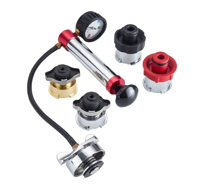
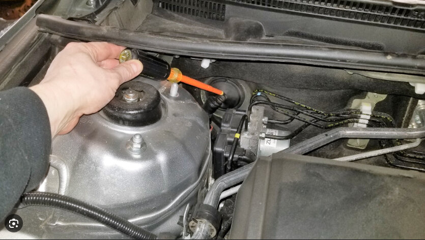
That link that I sent for the coolant pressure tester was for informational purposes only. I did not expect you to be able to purchase it from them. I assume in your situation you will need to use the resources available to you in your country. I have added a picture of the coolant system pressure tester for your reference.

Okay, if you say you checked the transmission fluid and it is good, then that is good.

However, transmission fluid needs to be checked when the car is running and up to operating temperature. If it has sat overnight and you are checking it before you drive it, most of the fluid will be in the transmission pan. Also, as transmission fluid heats up it will expand, so once you get it to operating temperature it will be at the wrong level.

Valvoline Max Life is a universal fluid. According to Valvoline, it is compatible with 95% of vehicles on the road today. It is far from specific. However, given your situation, I understand why you had no choice but to use it.

If the engine is not running correctly, then the transmission will not respond correctly. So, let's try to get the engine running better and see how the transmission responds.

For more specific help with your transmission, I suggest starting a new question specifically for your transmission.
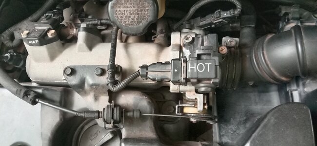
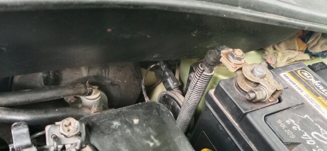
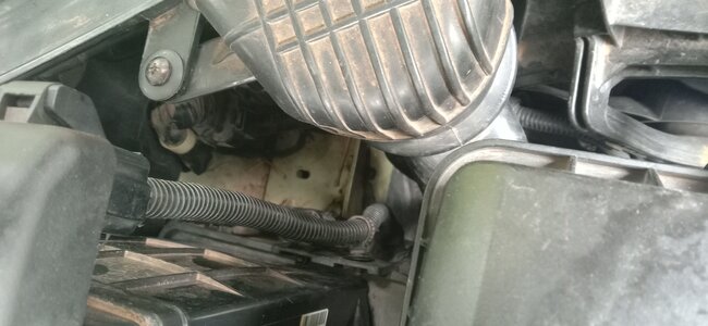
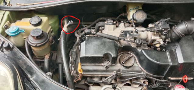
A/C line:
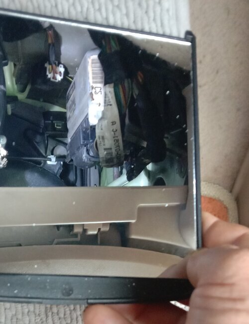
Okay, I see what you were saying not about the tape. That was awfully nice of them to leave those off.

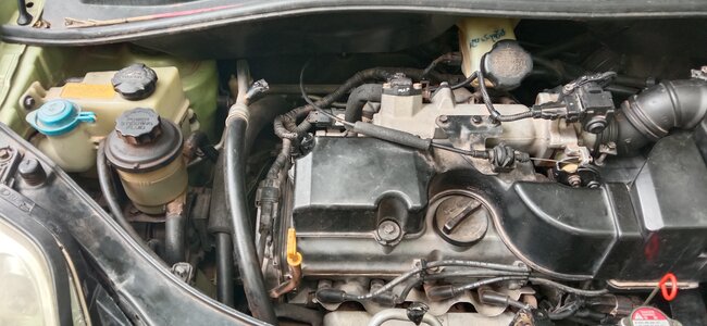
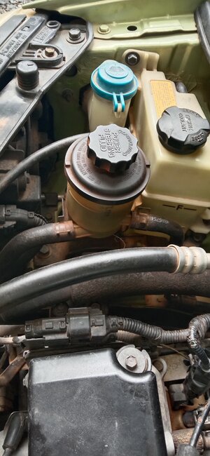
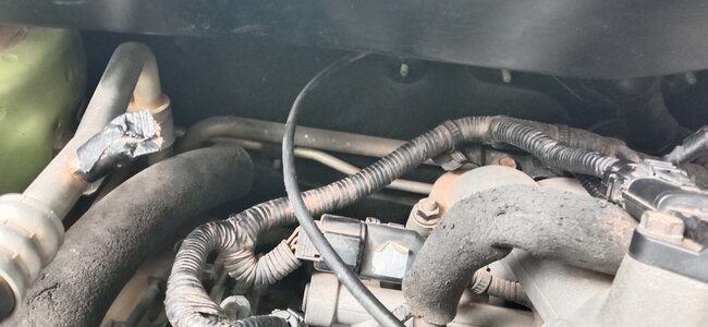
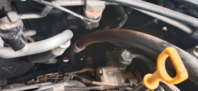
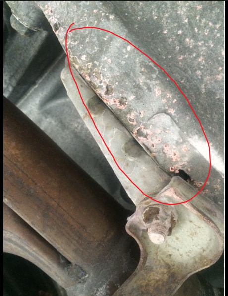
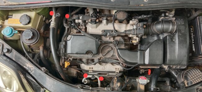
I did notice on the same hose we are talking about close to the radiator it seems to be covered in what looks like rust. This could be the radiator leaking and blowing back into the engine compartment as you drive down the road.

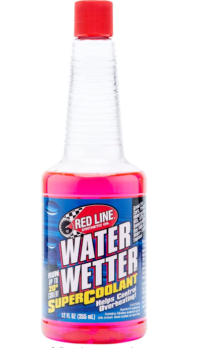
Water alone does not provide enough cooling for your engine. I understand coolant is illegal in your country, but there is that hot rod guys use because their vehicles are usually seasonal, so they don't need antifreeze. Those guys use something called Water Wetter. This will help regulate temperatures in the engine, reduce the surface tension of the water, improves heat transfer, reduces cylinder head temperature, and provides rust and corrosion protection. It also does not contain ethylene glycol, the main ingredient in antifreeze. You will have to look into it, but I think it may be a good middle of the road solution for you.

I found some on Amazon for you. I have also added a photo of this for you. Here is the link:
https://www.amazon.com/Red-Line-80204-Water-Wetter/dp/B000CPI5ZK/ref=asc_df_B000CPI5ZK?tag=bingshoppinga-20&linkCode=df0&hvadid=79852087642110&hvnetw=o&hvqmt=e&hvbmt=be&hvdev=c&hvlocint=&hvlocphy=&hvtargid=pla-4583451664389398&th=1
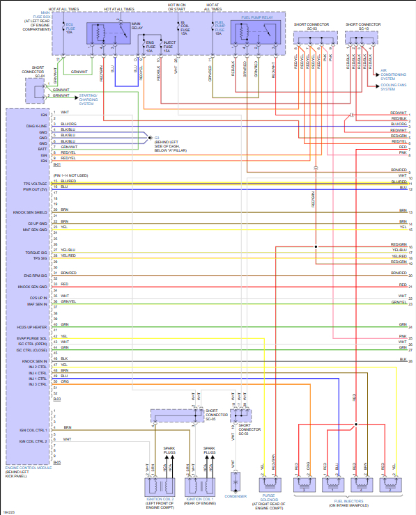
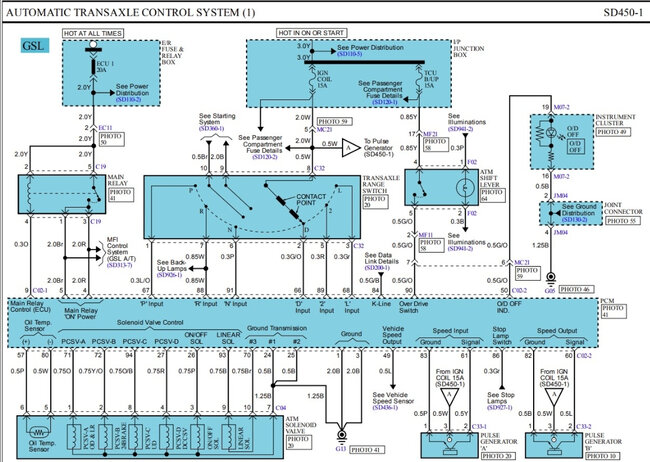
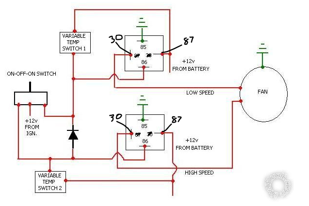
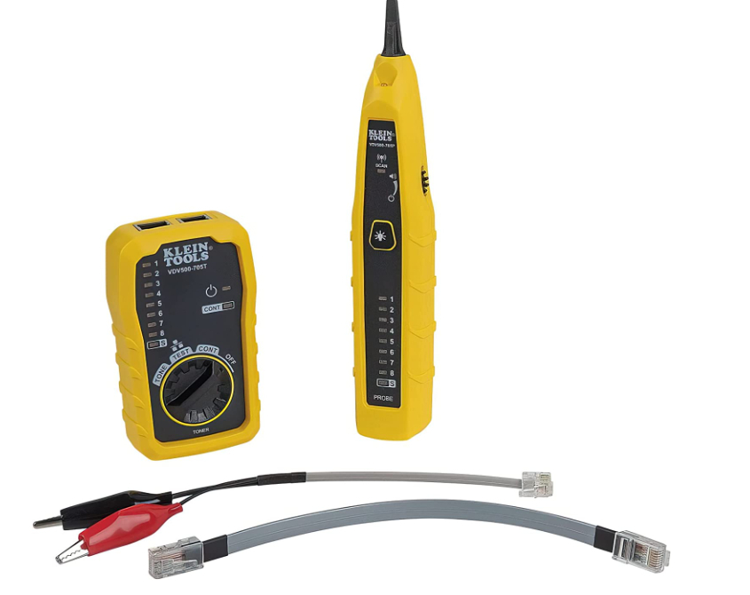
Now back to wiring:
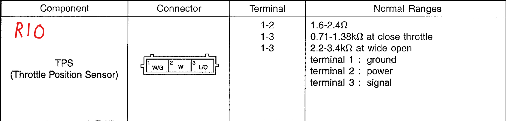
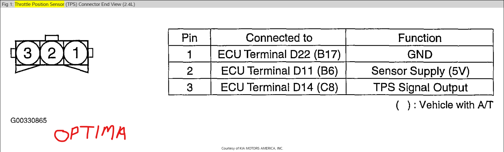
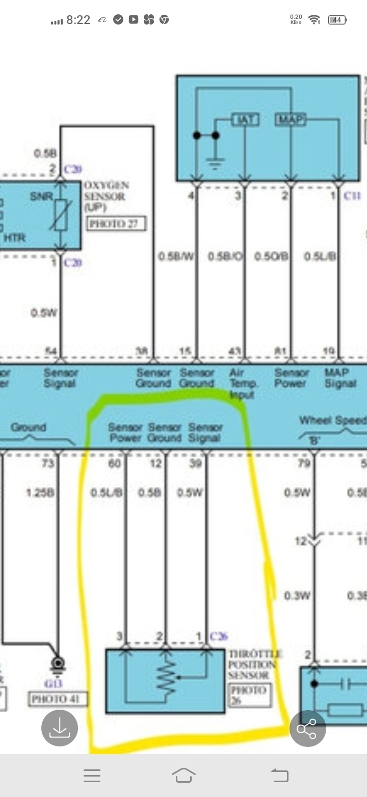
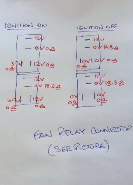
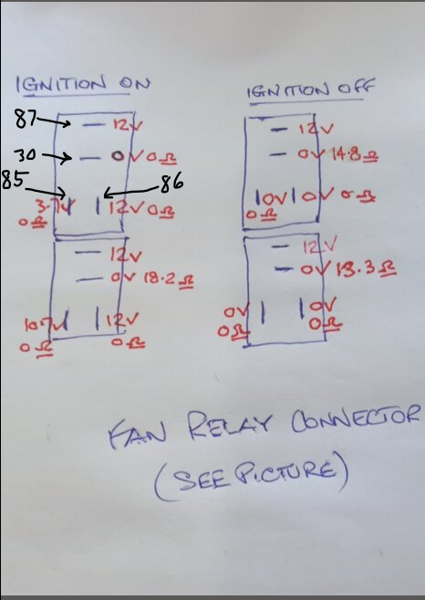
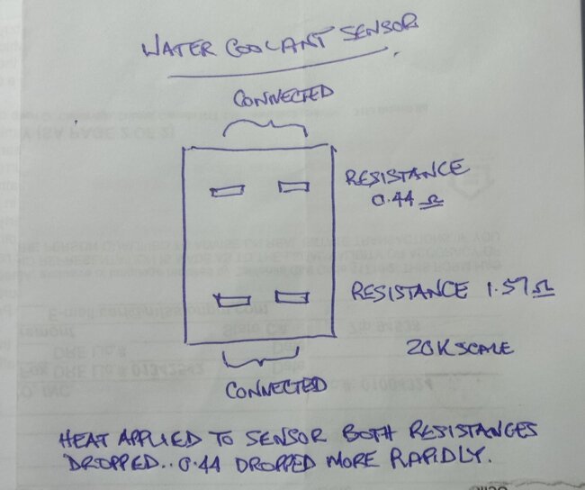
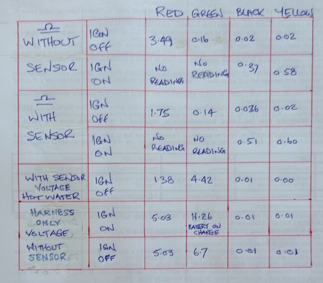
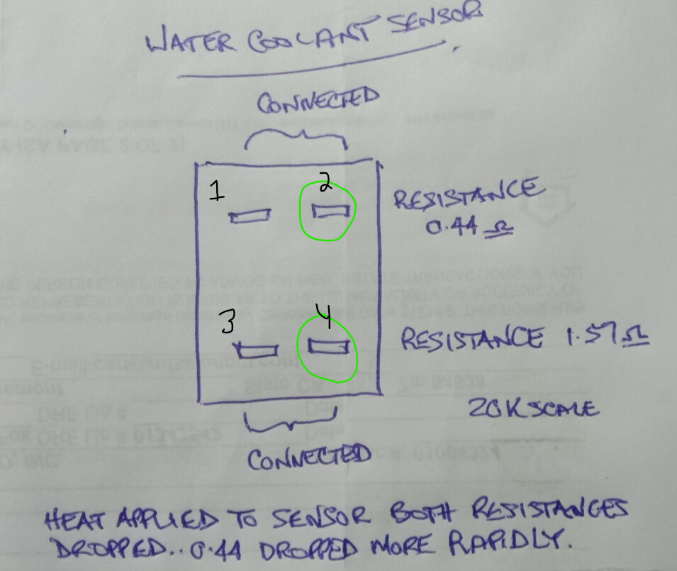
Thank you for giving me all those readings. They are very helpful, and the illustration was great as well.

As for your question about two switches in the cooling system - because you have a coolant temperature sensor and a resistor by the radiator, technically you have two switches.

However, if the resistor is bad the fan will only work at one speed, so it should not keep the fan from working. It is good that you tested it nonetheless.

When testing for resistance, we only check part of the circuit or wire. We cannot test resistance on live circuits (i.e. ones with voltage present). The voltage will skew the results of the test because the meter is trying to use a voltage drop to calculate the resistance of what we are testing. This is to look for either high resistance or a break in a connection/circuit.

Since we observed 12 volts and we have a 12-volt circuit, we don't need to measure resistance. We can infer from our voltage reading that there is no voltage drop, meaning there is little to no resistance in that part of the circuit.

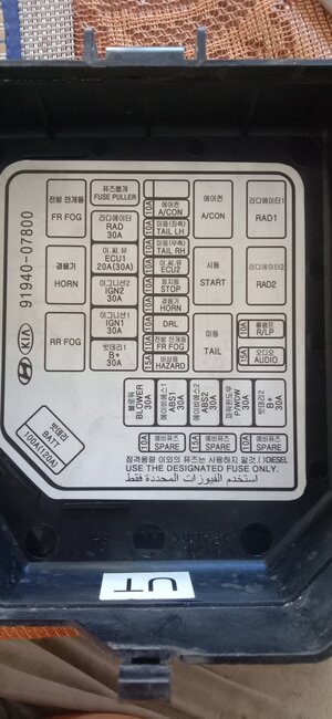
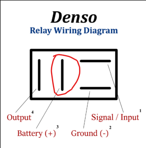
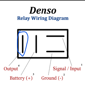
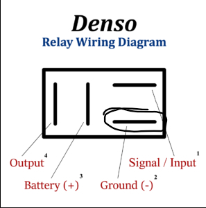
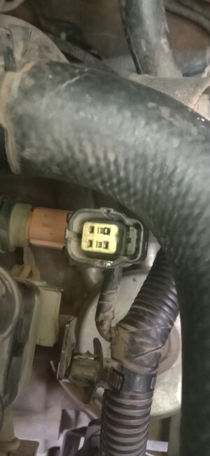
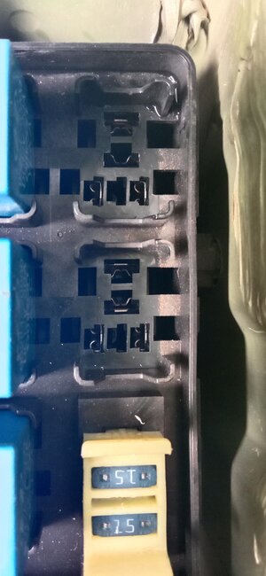
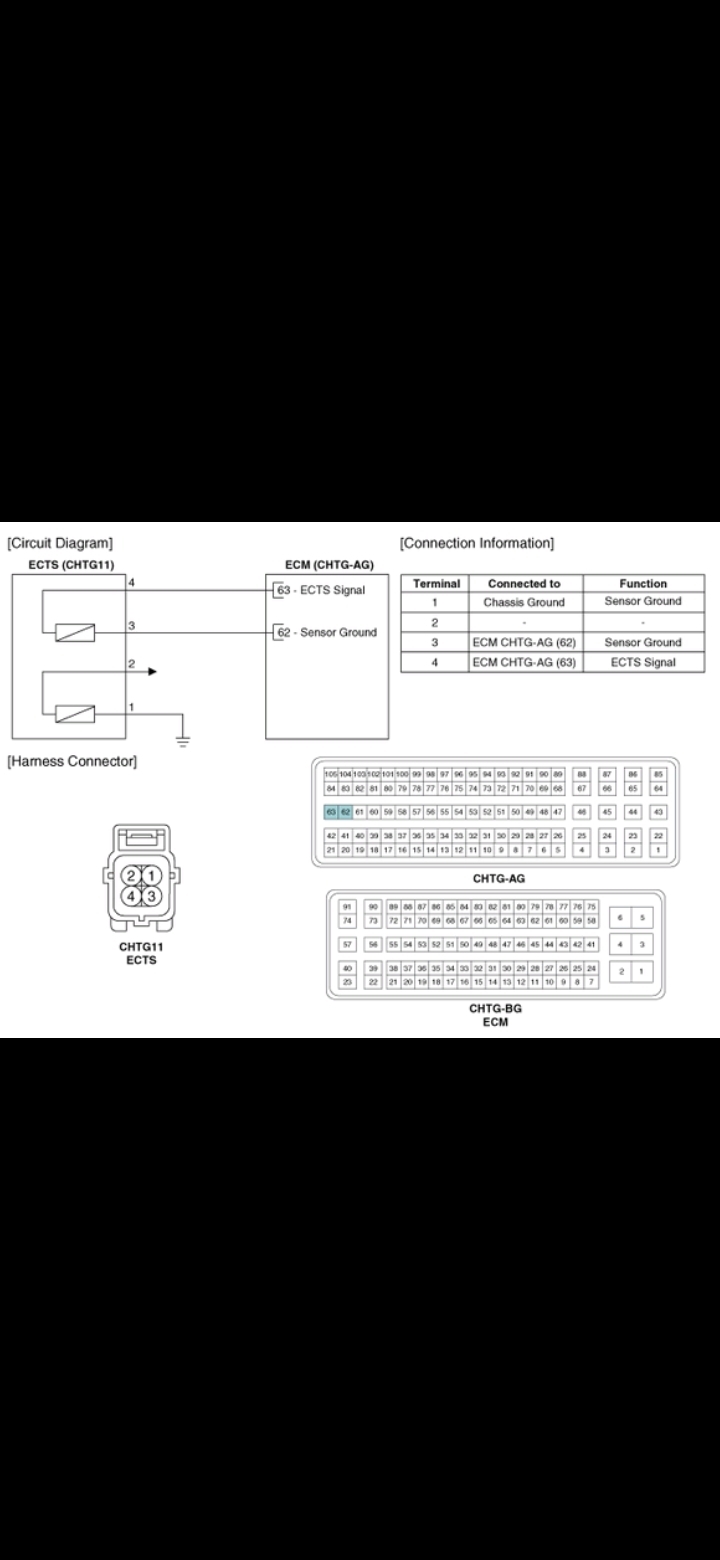
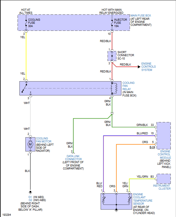
What we know from our tests: (terminal identification)
87-12(+) Hot-This terminal has a constant 12-volt source whether the key is on or off.
30-Output to Device- In our case to the fan.
86-12 volt switched- This terminal only has power with the key on.
85-Ground/Signal- This terminal is controlling the ground side of the circuit, completing it using the PCM or it goes directly to the temperature sensor.

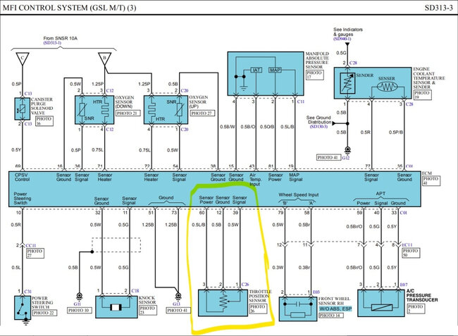
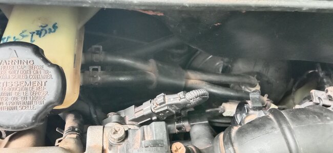
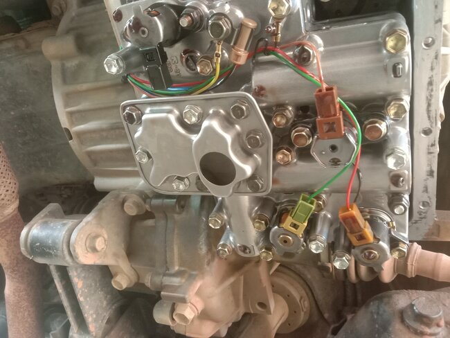
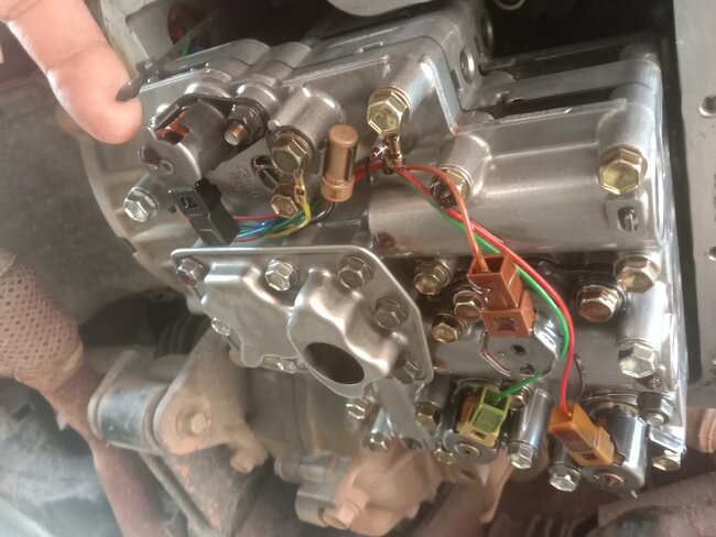
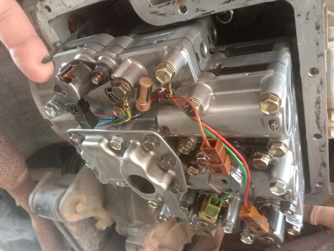
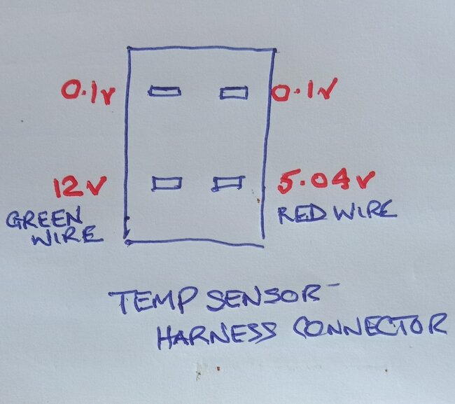
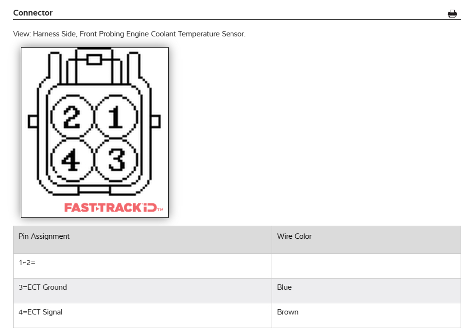
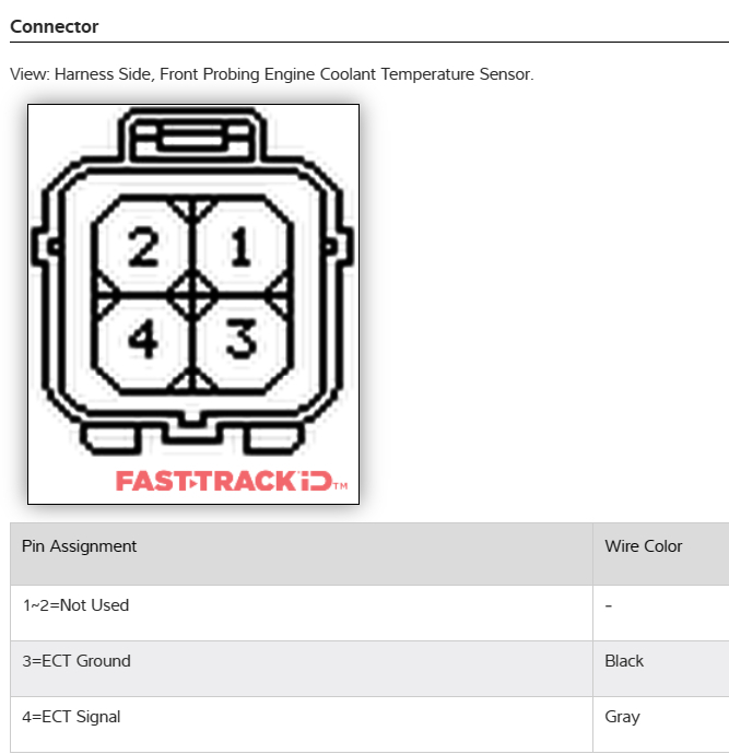
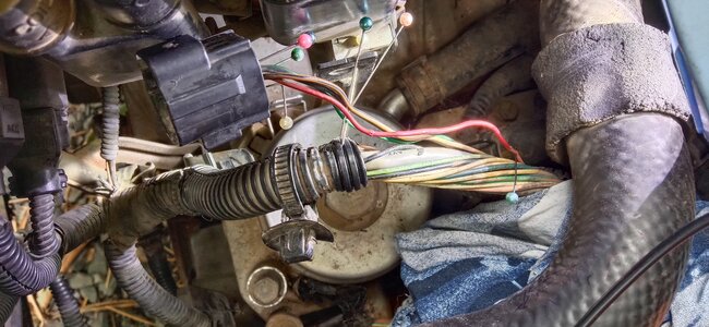
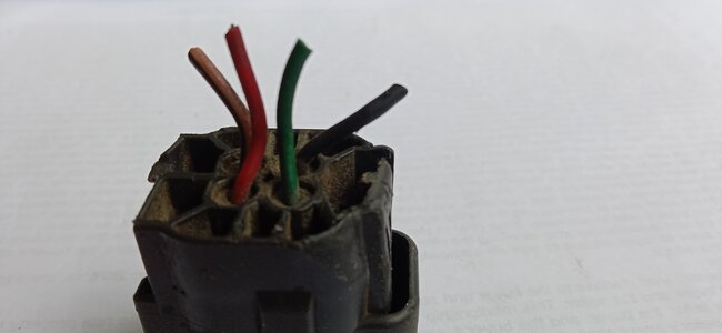
Now that we have pretty much identified the fuse relay area, let's see if we can identify the wires on the temperature sensor.

We also know that the fan power and ground are good because the fan operates from the relay center when you jumped terminals 87 and 30.

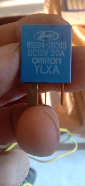
We know that the relays are good because you tested those.

We also know that both power supplies are working properly.

So, the last thing that we need to figure out is where the coolant temperature signal to the relay is coming from. Then we can better understand why the fans are not turning on.

Test: (done using voltage setting only)
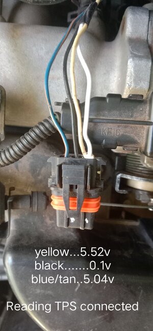
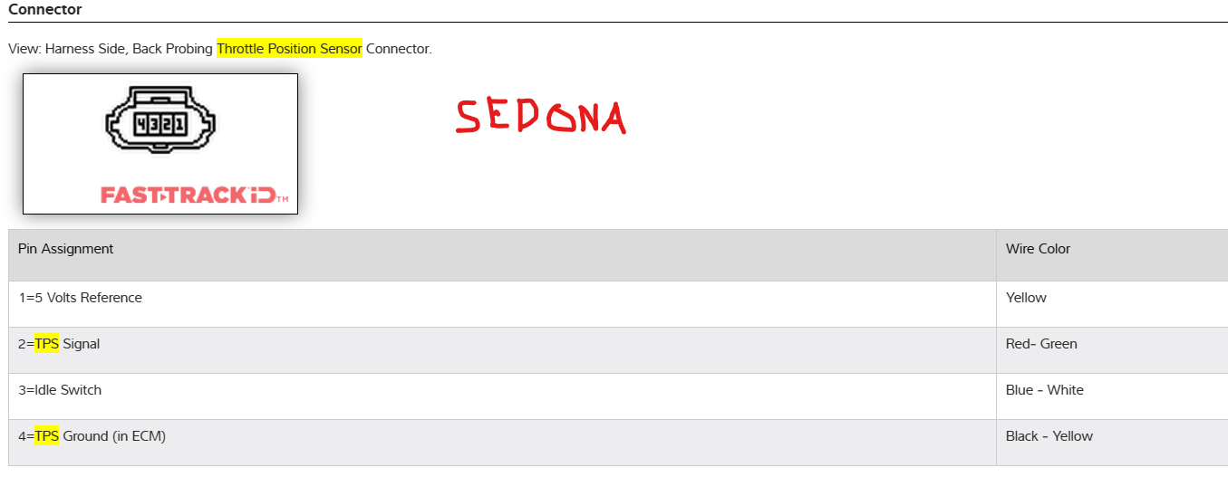
First, unplug the sensor and test at the connector on the harness. See if you can find a 5-volt source like you did before for the TPS. You may have two 5-volt sources like you did before. Now record your findings. We will see if one goes away in the next test.

Second, plug the sensor back in and back probe the connector and do all the same tests and record your findings.

Lastly, get the vehicle up to operating temperature and again perform the same tests the same way and record your findings. Once the vehicle is warmed up, you may turn off the engine, but turn the key back on the take your measurements. Since the coolant is still hot, it should still give you an accurate reading.

Let me know what you get for results. These tests should help us identify the 5-volt reference from the PCM and any signal wires. Then we should be able to determine the ground as well.

Some info for you:
There are two types of coolant temperature sensors generally. One is a positive thermal coefficient (PTC). This sensor, as the temperature in the engine rises, the resistance also rises which will result in a lower voltage reading on a signal wire as compared to when we previously tested when the engine was cold.

Negative thermal coefficient (NTC) - this sensor, as the temperature in the engine rises, the resistance will decrease resulting in a higher voltage reading than when it was cold.

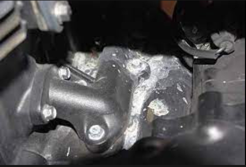
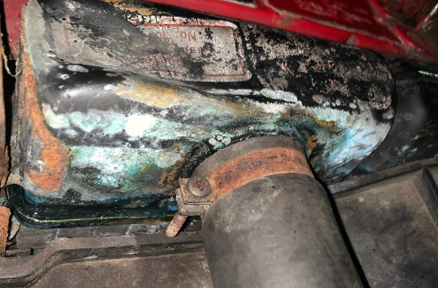
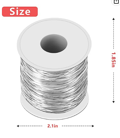
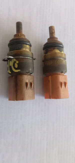
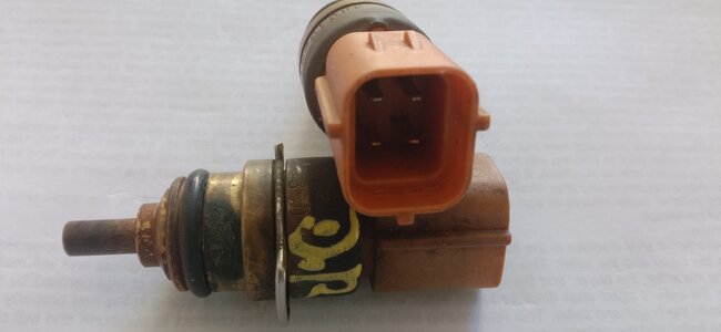
Because you are using only water, you may have a lot of corrosion inside your cooling system. So, I would remove the temperature sensor and see if it has any rust or corrosion build-up on it. If it does, see if you can clean it. This will keep the sensor from reading the temperature properly and could be the cause of the fans not working. Before you remove it, make sure you either have some nylon thread tape or some thread sealant so when you reinstall it, it does not leak.

If it is severely corroded, completely draining and refilling the cooling system with fresh water would be a good step to try to remove as much rust a possible from the system.

Here a few articles concerning electrical testing and some other resources which I thought you may find useful:

https://www.samarins.com/glossary/coolant-temperature-sensor.html

https://www.fluke.com/en-us/learn/blog/electrical/what-is-ohms-law

Please let me know if you have any questions about these tests or I can help guide you.

Over the last 6 days of talking to you, you seem to have a pretty good handle on testing so I think you'll be fine but let me know if I can assist.

Thank you,
Brendon
Jul 16, 2023 at 2:53 PM
Avatar
LESLIE PAYNE
  • MEMBER
  • 42 POSTS
Hi Brendon,

In tropical climates rains are very intense with deluges and strong winds. It rained nonstop all night, and I am waiting for a break to do more on the car.
Re your comments:
I always check transmission fluid level when the engine is hot, usually after returning from driving.

I will start a new question regarding the transmission problems. I have been worrying about it because we do not have transmission repair shops here. We do not have car scrap yards either (never understood why this is) and so most times a big transmission problem can result in scrapping the car. Solenoid replacement I can do but clutch problems would be a major problem for me.
Please let me know if you are aware of a reputable supplier of solenoids and one that can positively identify the solenoids for my car.

When I bought the car it had a bad radiator cap which I replaced. The rust you saw in the pic is from the previous cap, I could not remove all of the staining.

Amazon shows the coolant fluid alternative as not available. This maybe because they cannot ship by air, I will try and find here but doubt I will be successful.

The coolant sensor is in a very bad location. The intake air ducting, battery and other bit and pieces need removal. I took the pic of the connector during the TPS work and also measured the voltages at that time, pic is attached.
Please note the 0.001v reading, it maybe 0.000. The digital meter occasionally will not read 0.000 with completely disconnected, I don't remember it this was the case.
No
To pin the connector may require removal of a large coolant hose because it's directly on top of the connector so I think I will drain the coolant system at the same time and remove the sensor for inspection.
I will check if new one is available, it would be prudent to replace it now.
I will then place the pins in the connector before reconnecting the coolant hose and refilling the system.

This might take me a couple of days due to weather limitation so please anticipate a delay for a reply with the results of your other instructions.

I have made an assembly with a switch, fuse and spade terminals to allow me to operate the cooling fan.
I was intending to use terminals 87 and 30. Since 86 is controlled by the ignition should I instead be using 86 and 30 to avoid lifting the hood every time to operate the switch?

Thank you again.

Jul 16, 2023 at 8:42 PM
Avatar
LESLIE PAYNE
  • MEMBER
  • 42 POSTS
Hi Brandon,

I think I have found the computer on the passenger side wall, behind the glove box and quite high up

The pic attached is my camera facing down into a mirror (black frame) which is reflecting up behind the glove box. A flashlight is providing light

I have two questions:
1. With our recent progress do we still need to find access to the computer?

2. If we do need access, then is the glove box typically removable? The box and its facia appear to be one assembly, I loosened the only 3 screws I could find but it remained rigid. Are they usually separate or part of the entire dash?

Thanks.
Jul 17, 2023 at 4:47 AM
Avatar
BRENDON S
  • CERTIFIED EXPERT
  • 653 POSTS
Hello LESLIE PAYNE,

Oh, I see, I am sure it would make it impossible to do anything in that weather. I live more northern, closer to Canada. We don't usually get rain like that. But I can see how it would be an issue. No problem though, I am not going anywhere so take your time.

Awesome, nice find! That looks more like the picture I found. You were right though, obviously that guy on eBay had no idea where it was lol. I think for now we should note its location and continue working on the fans. We may need to get to it for some tests but for right now I think our problem might be at that temperature sensor or a wire going to it.

The glove box should be removable. Usually, the door will come off separately and then you can take out the inside part so you can get behind it. You may see some foam rubber pads for the glove box door, sometimes there are bolts or screw behind those. They tend to hide most of the screws to make it look better. Removing interior parts is a lot like working on electronics. Just when you think you got all the screws out there is one hidden somewhere.

But for now, I would leave it in and if we have to remove it, I will see what I can get for instructions on my end.

Honestly you seem to be really good at taking things apart, which is skill a lot of people don't possess. I think you will be able to look at it and see how it comes apart. It usually isn't held in by much. But like I said I will try to find some instructions if we need to get it out.

That's good so the fluid shouldn't be an issue. Very well could be because of engine issues. The transmission and engine use a lot of the same inputs, so definitely possible an issue with the engine is causing the shifting issues.

So, I would wait to start a new question until we get the engine running correctly. The other reason is everything we are talking about and working on, will be available to everyone. So, if someone else has a similar issue with this vehicle, the information is organized so others can find it.

The coolant additive, Water Wetter, let me see if I can find some other sellers for it and I will send you some links. Have you been able to get things from eBay or Amazon before? Trying to see what our options are so I don't send you useless links.

The temp sensor, thank you for getting some readings, let me see what I can come up with from that. Usually, I don't recommend replacing parts until we verify, they are bad, but since we are kind of flying blind here and you will be already draining the system and they are usually not expensive. I think in your case though, it's not a bad idea. At the very least we can rule it out.

The fan set-up you made sounds perfect for now. Unfortunately, I wouldn't hook it to terminal 86 because that is the control side of the relay, which uses the same 12 volts but has a lower Amperage or Current to control the higher current used for the fan. It may burn up the fuse box or melt insulation off the wires. You could tap into a fuse that only has power when the key is on. Like a 20-amp fuse just like the relays already use. But without the proper fuse tap you would have to solder the wire to the fuse which could make it too thick to fit back in the fuse box correctly and could cause more issues.

I think the way you have it now is the best and safest way. You can run the wires for the switch through the firewall so you can have the switch inside and don't have to pop the hood each time. Keep in mind you will have a live wire in there after this just hanging so it is best to mount the switch if you can, maybe on the bottom of the dash so you can reach down and flip it on. If it happens to touch something it could cause a big problem.

I added a picture for you. If you run the switch through a boot like this, (see image) it will be a safe and watertight way to get the wires through the fire wall. A thin piece of rigid wire with a hook on the end, pushed from inside will help a lot. Then you can wrap your wire onto it and easily pull it through. Just be careful not to damage any existing wiring. Something like bailing wire or mechanics wire would work well. Something about 18-20 Gauge wire (see image). A metal coat hanger would work but it is a little thick so if you use that just be careful.

Here is a helpful link for running a wire though the firewall. They are installing an amplifier, but the process is the same for all wires.
https://www.crutchfield.com/S-jIIXGq1b3ep/learn/how-to-get-through-your-cars-firewall.html

The connector at temp sensor:
The 12 volts is unexpected. You should only need that 5-volt reference provided by the computer or 12 volts supplied separately, having both seems odd.

I know you can't get to the sensor after it is warmed up because of that coolant hose but maybe you can get to it after you drain the coolant and back-probe it and see what changes.

I am going to look more on my end and see what I can find out about this. It might be a short to power somewhere. Strange. There is practically nothing about 4 wire temperature sensors, but I will keep looking and see if that is normal or not.

But like I said take your time, when you get to it, you get to it. I'm not going anywhere, and this will allow me more time to try to get some better information for you.

Thank you,
Brendon
Jul 17, 2023 at 8:09 AM
Avatar
LESLIE PAYNE
  • MEMBER
  • 42 POSTS
Hi Brendon,

This is the 3rd day of nonstop heavy rain and fierce winds. It can rain for weeks here with roads closed etc., very normal. Your weather must be lovely now.
Just had internet restored from broken cable. Normal to hang internet cables from trees, high winds topple trees and no internet.

I have started a new question and a brief response from a person Ken L.
Suggested a sensor so written back asking for more info.
I have determined that his sensor and our coolant sensor are not available, need to be ordered online from different country, disappointing. I hope Ken can provide testing info to verify if it is in fact the correct faulty sensor before ordering.

A local fellow sold me a secondhand coolant sensor to try, claimed it was interchangeable. Looks the same with 4 wires, different colors but all smaller gauge. On my sensor 2 wires are much thicker. Do you anticipate a problem?

Re coolant additive. We usually order components through Alibaba. Mail theft is a big problem, when mail workers see a USA postmark it is thought to be valuable and often never arrives, even with tracking.

I found an old communication on your site from a person also in Cambodia. There is no contact info for him, does your site provide it?
It would be good to know where he purchased parts. Having to operate it under the hood is okay.

I thought the relay control would have insufficient amps but thought I would ask. I bought a Chinese made switch for the fan power, it was rated 20 amp but lasted maybe 10 minutes and started to melt. I am sure you will smile but I solved the problem with a 32amp, 240v, residential disconnect. Attached the fuse on the side with hot glue. Hopefully it's only temporary but works great.

Thanks for all the other info you provided. When the rain stops, I will get back to the car.

Thanks.


Jul 18, 2023 at 1:33 AM
Avatar
BRENDON S
  • CERTIFIED EXPERT
  • 653 POSTS
Hello LESLIE PAYNE,

Wow, that is crazy, weeks of rain and wind! Must be a mess. I do not like the rain myself. It is pretty nice here right now, really humid but most of the year it's snowing and or cold. So that's miserable. Glad to hear you got your internet back up though.

Ken L is really good and definitely will be able to help you. He has been doing this for a long time.

The sensor I wouldn't use unfortunately. The thicker wires are probably power so it might just burn it out and work at all. Plus, the wire positions might be different. Sometimes taking the old one out and cleaning it can fix the issue.

Here is a video I found for testing the temp sensor. Try it, when you can, and see if you can get a reading across any of the 2 terminals. On the video he shows a 2-wire sensor but looks like he is testing with a four-wire sensor. I would say give it a shot so we can see if it is changing resistance as it heats up.
https://youtu.be/LAx5-Oj1AVE

See if it helps. Hopefully at the very least we can figure out what terminal is sending a signal.

I will look and see if I can find an Amazon or eBay seller that is in Albania for you. Is there any way to get parts from KIA directly from Korea? It might be the best option. I know you mentioned they weren't really helpful in the past though.

The switch melting is one of the reasons they use relays in the first place. Did the fuse burn out when this happened? Was the fuse before the switch? If not, it should be, or it won't protect it. However, the fuse rating and what amperage burns out at is different. Sometimes amperage can spike to 160 amps before the fuse blows.

The household light switch, normally I would laugh if a car came in with that but because of your situation, you have to work with what you have. If it works and you can use the vehicle when you need to until you get it fixed, then why not?

Just be careful, as improper wiring will cause a fire. So please keep a close eye on it.

Also, you are very welcome. I hope it has been helpful. I wish I had more information on your vehicle, it is very difficult to figure out wiring in a car with no diagram. If I had it in front of me that would help but still wouldn't be easy.

Of course, it has to have a four-wire temperature sensor too, lol. Just complicates it more. Oh well though. Try the video I included when you can get back out there. Like I said I am not going anywhere. So, when the weather is better and you can try some of these other tests, hopefully they will give us some information so we can lay this circuit out and see what is going on with it.

Stay safe.

Thank you,
Brendon
Jul 18, 2023 at 6:23 AM
Avatar
LESLIE PAYNE
  • MEMBER
  • 42 POSTS
Hi Brendon,

First may I say how much I appreciate you responding predictably fast, allowing me to progress rapidly. Ken L so far has not done so.

Weather prediction say rain continuously for the next week. I decided to work in the rain (warm rain) and get the sensor out. Water was surprisingly clean and sensor almost no ruat deposits.

Attached are the readings I got.

I was wrong about the used sensor I bought sensor having 2 thicker wires, different colors but all 4 wires are infact the sames size.

I have been working hard to locate a new transmission speed sensor. Because of currency/language ($ used in Cambodia) I tried in USA but am being told Kia never sold Morning or Picanto there, is that true?

Thanks.
Jul 18, 2023 at 10:25 PM
Avatar
BRENDON S
  • CERTIFIED EXPERT
  • 653 POSTS
Hello LESLIE PAYNE,

You are very welcome. I wish I had some information on your vehicle so we could make more progress and get your problem solved. I really appreciate your kind words.

Yes, that is correct. The Kia Picanto nor the Kia Morning, were ever sold in the U.S., this is why I don't have any information on your vehicle. I am working with the information you have been providing, which I might add is very good, as well as my experience and other sources.

Currently we are only licensed to obtain information for vehicles sold in the United States. We are however, working diligently to get a license for Eruopean information as well.

Ken L does about 40 times the work I do. He deals with over 40 people a day, 7 days a week. For I believe the last 20 years. From what I understand, his mother actually started this website. I have been working mostly with you only, because you have a lot of things going on and I would like to help you get this fixed as fast as possible. Since I don't have any information, I spend a lot of time trying to find anything and everything about your vehicle. This is one of the reasons I am able to respond so quickly.

He is also a great guy and I have a lot of respect for him. He is the one who gave me this opportunity to help people.

As far as the temperature sensor or any other part. If you can get a part number via internet search or maybe a dealership, you can use that and do an internet search. Sometime part numbers can also be found on the part themselves.

If a part has the part number on it, it is usually 5 digits, a dash and 5 more digits. Thet are alphanumerical also. Sometimes it will say KMC, which stands for Kia Motor Corporation, I assume. This number is what you can use to do some internet searches.

Here is a link of country codes used for the internet. You may find that a website has a part but doesn't deliver to your country. For example, you found an Australian website that has Kia parts. It will say ".au", you can try changing it to ".al" for Albania and see if that will help.

Here is the link:
https://en.wikipedia.org/wiki/Country_code_top-level_domain

Let me know if you can't access it and I will send you some screen shots. You can also google, "Country code for top level domain".

I am trying to find a 4-wire sensor diagram so we can figure out if you should have 12 volts and 5 volts on that sensor. I would think you would only need one or the other. Both sound odd. But without any wiring diagrams to see what this is connected to it is difficult to tell whether it is normal or not. Normally these sensors are connected directly to the PCM which normally puts out around 5 volts.

So far, every Kia I have looked at in the United States sold over the last 20 years, none seem to have a 4-wire sensor.

But I will continue to look and see what I can find on my end.

There is a tool that cable installers and lineman, plus others, use to find breaks in wires. It sends a signal down a wire and is picked up via a handheld receiver. You can find not only breaks in wires but trace the entire wire to see where some of the harnesses are going, which will help map the electrical circuits.

Here is the link:
https://www.amazon.com/Klein-Tools-VDV500-705-Generator-Alligator/dp/B084LKVBM5/ref=asc_df_B084LKVBM5/?tag=hyprod-20&linkCode=df0&hvadid=459657803259&hvpos=&hvnetw=g&hvrand=15887383288062128504&hvpone=&hvptwo=&hvqmt=&hvdev=c&hvdvcmdl=&hvlocint=&hvlocphy=9005097&hvtargid=pla-997330532527&psc=1

Klien is a good brand in my opinion. I have a lot of different testers from them that I use in my house and the garage. I frequently recommend their products to customers.

This tool will help you trace wires without having to pull the harness apart in most cases.

I am very surprised as well the coolant was so clear, and that sensor was clean as well. I assumed it would be very rusty. But it is good to know the coolant system seems clean and the sensor so far seems good.

Where you able to try this test and see if you can locate the signal wire? There may be more than one. If you haven't, please give it a try. If we can identify the signal wire and see how it the sensor responds to heat, we will have a better idea of the circuit layout.

Here is the link again for you:
https://youtu.be/LAx5-Oj1AVE

Thank you,
Brendon
Jul 19, 2023 at 2:54 PM
Avatar
LESLIE PAYNE
  • MEMBER
  • 42 POSTS
Hi Brendon.

I watched the video but I think I am stuck because it needs testing back to the computer to trace a wire break and so we are where we were with the TPS. He is also only referring to a 2-pin sensor so i don't know how to interpret the second pins.

The weather is really preventing from me doing anything electrical in the engine bay. To give you an idea of the constant rain our local weatherman recorded 3.1 inches of rain yesterday, 2.2 inches overnight it has not stopped yet at 10am. We are now in our 4th day of non-stop rain, and it's predicted to rain continuously for another week.
Your prompt replies really are helping my spirits also. I have been getting quite low because of the car, the constant rain compounds it. I wish I had chosen a different brand of car, that's for sure.

Okay, regarding the temperature sensor. Yes, it does have a part number 38010 on the brass body and PA66GF30 on the plastic portion. I find lots of advertising online for it. I attach the Ebay ad link because it says compatible with 399 vehicles and quotes 2018 Sonata and Santa Fe that use the same sensor and assume that these models are sold in the USA. All are 4 pins.
https://www.ebay.com/itm/354765387359#vi-desc-maincntr

I do have a non-contact wire fault finder that I will try, it's for household wiring but might work. Same problem is as before though because the harness length is only about 10 inches long the disappears into a large bundle.

In my search I am finding complaints from some Kia buyers, mostly about the Rio, that vehicle Vin numbers call for different parts to the car. Parts records don't match. My Transmission speed sensor is the same, everything I find online for my Vin is for a totally different sensor, physically not interchangeable. My sensor shows for a Kia Atoz and apparently it is a no-longer manufactured part. Generation 1 for my car is late 2003, mine is 2004 so early in the build. I am wondering if Kia swapped some Hyundai Atoz parts because of maybe shortages and its not reflected in their parts list. I read that Hyundai and Kia share transmissions in some instance and mine may actually be a Hyundai transmission. It's a problem because the parts have been discontinued.
Have you come across this before?

Do all engines have identifying numbers? Can that number be used to trace its origin say an Atoz design/engine? If so, where would the number be?

Writing early because I'm really at a standstill. Thank you for your dedication because this must have be a frustrating project.


Jul 19, 2023 at 8:42 PM
Avatar
LESLIE PAYNE
  • MEMBER
  • 42 POSTS
Hi Brendon,

Rain has finally eased. If it holds, I will do more tomorrow.

I measured the resistance between the pins in coolant sensor to better understand how it's connected.
The 2 upper pins are connected together.
The 2 lower are pins are connected together.
No connection from top to bottom.
The resistance values are shown in the attached sketch.
I applied a heat to the sensor briefly and noted both upper and lower readings dropped, the upper moved faster than the lower.

I took the readings but do not know if they are of any value or how to interpret them.

I have been searching for 4 wire sensor connection wiring and the internal connection detail of the sensor but could find nothing, all are 2 wires.

I have watched the YouTube video several times but don't understand how to apply to our case.
Can we assume that the 5.04v is the signal wire, ign on?
Can we assume that 0v is the ground, ign on?
My meter occasionally will float up from 0.000 to 0.001 and 0.002 so I think the 0.002 may be a ground.
I don't understand the change in reading when ign on or back pinned.
Don't know where to look for the 12v without access to the computer.

Thanks.
Jul 20, 2023 at 5:06 AM
Avatar
LESLIE PAYNE
  • MEMBER
  • 42 POSTS
Hi Brendon,
Is this what we have?
Jul 20, 2023 at 7:13 AM
Avatar
BRENDON S
  • CERTIFIED EXPERT
  • 653 POSTS
Hello LESLIE PAYNE,

Wow, that's a lot of rain! Glad it stopped though, at least for now.

Most engines have identifying marks but are usually hard to locate. In the U.S., the 8th digit of the VIN will tell you what engine it has. I am not sure if they use VIN's in your country though.

Here is a VIN decoder for you:
https://detailedvehiclehistory.com/cambodia/vin-check

Here is a couple links with some information on your vehicle:
https://www.ultimatespecs.com/car-specs/Kia/4292/Kia-Picanto-11.html

https://www.ultimatespecs.com/car-specs/Kia/M658/Picanto?sort=engine

Thank you very much for all your awesome testing. Without that, our diagnostics would be much more difficult. Vehicles are frustrating; however, I personally like the puzzle and I like to help people. So as long as you are willing to keep working on it, I am willing to work with you to get it fixed.

The video was just so we could find what is connected inside the sensor.
It is starting to look like this sensor has 2, 2 wire sensors. Can you tell me what the wire colors are?

That sensor you found looks right to me. As long as it is held in by a clip. When I looked it up for those vehicles Hyundai Sonata and Santa Fe, they have a 4-wire connector but only 2 are used. That is why I am thinking there are two sensors built into yours. Plus, the top isn't connected to the bottom.

But since yours is sold in a different country you might be using both.

The wire that has 0.44 Kilo Ohms, would be 440 Ohms. If this is a ground there is way too much resistance. A ground shouldn't have more than 5.0 Ohms.

If you still have it out, can you send me a pic of it?

Nice job on finding that other sensor and all that other information. Since the seller is based in China, you should be able to get it. I mean for 11.99 or 49,545 Cambodian Riel, I am not sure if this is your currency or if that is really expensive in your area. If it is cheap, it might be worth it to get it and see if the fans come on.

I found a video on someone changing the Temp Sensor on a Kia Picanto. The sensor doesn't look that bad, but he still had an issue with it.

Here is the link for you:
https://youtube.com/watch?v=IF6hnisKh0Q&feature=share

You could, if you still have it out, plug it in, back probe the connector and set meter to volts.

Put red lead on back probe pin and black lead to somewhere on chassis.

Turn the key on and note the voltage reading on the on the wire that had 1.57 Kilo Ohms.

Around 30 degrees Celsius or 90 degrees Fahrenheit, you should have around 3.25 volts. Since it is pretty warm there and you are handling the sensor, I assume the sensor will be around this temp, since humans body temps are around 98.6 degrees Fahrenheit, which is closer to 36 or 37 degrees Celsius.

Then try heating the sensor and see how much it changes.

Here is a link to some tests. It also includes a temp chart.
https://autoditex.com/page/engine-coolant-temperature-sensor-ect-13-1.html

Now these may not be the exact numbers for your vehicle but getting these readings, with the sensor cold and then warmed up, will help us to see if it is at least close to the right range.

The resistance on the top circuit seems way out of range, if it is used. The bottom circuit seems ok but seems a little high. I am curious if it isn't sending the right voltage when it gets hot.

Is the tool you have a voltage finder or is it a tone generator? If it is a tone generator it should work, even with the big harness. If it is only a voltage tester that just tells you if voltage is present, usually they don't work for anything under 50 volts.

Parts are discontinued all the time unfortunately. It depends on how popular the parts are, length of time and other factors. Most people go to the parts store to get temp sensors because the dealerships price the parts so high, no one will buy them. So, the temp sensor being discontinued is no surprise.

Also, Hyundai and Kia, are the same brand, so I'm not surprised if some of the parts are from Hyundai.

Here is an article about symptoms related to a bad ECT. Looks like a lot of matches. Also, if you transmission is Electronically controlled, this could be causing the shifting issues as well.
https://mechanicbase.com/coolant/engine-coolant-temperature-sensor-symptoms/

I have added a connector end view for the Sante Fe and Sonata for you.

Yes, the image you just sent me looks like it may be very close to our circuit.

It seems like the 5 volts is the reference voltage produced by the PCM and the ground goes from the sensor back to the PCM which is providing the signal to the PCM.

The top circuit is strange. It may be for a different component.

Also, I have added an image from the 2004 Kia Rio. See if any of these wire colors match.

I would also test for voltage at the resistor on the fan shroud or radiator, that you tested before. Just to see what we get.

I think whatever is causing the symptoms you are experiencing may be caused by this fan issue. Normally if the resistor is going it will cause the speed to change on the fans or stay at one speed but should keep it from operating.

Let me know what you get from this information.

In my opinion it seems like our issue may be the temp sensor itself.

Let me know how it goes or if I can help or clarify any tests.

Hope you have a good day and try not to stress. I think you are doing great. I wish more people would give me as much information as you have. So, hang in there I think we might be closer to figuring out what is causing the issue.

If you have to take a couple days because of rain or just need a mental break, which I completely understand. Sometimes it is best to walk away for a little while, take a break, so you can clear your mind.

Thank you,
Brendon
Jul 20, 2023 at 9:19 AM
Avatar
LESLIE PAYNE
  • MEMBER
  • 42 POSTS
Hi Brendon,

Thank you for the info.
I will read it all this evening.

Yesterday because of the rain, I wore rain gear and took my moped to where I bought the temp sensor. I had read online that the one in my car is common to many cars I see in Cambodia. I took it with me and asked if he could find the exact model number. A couple of hours later he called and said he had one, used of course, but in good condition.
It had the connector attached and had the exact same wire colors. Excited, I tried in the car, heated with boiling water but the fans still did not turn. Now I don't think it's a sensor problem.

Anyway, the rain was intermittent, so I got some readings. I did not know how to present them, so I hope the chart makes sense.
The "battery on charge" comment was because it started raining heavily for a few hours. When I returned to continue, I found the ignition had been on and the dash lights were not as bright. The 11.26 battery voltage reading is low because of that.

To make sure there was not a wire break close to the harness I stripped it back beyond where there would be any flexing and pinned the wires. I took readings in the connector, just before the connector in the harness and about 12 inches before the connector and found no problems.

I have sent pics of the sensor.

I did not see an engine number so I will have to search some more.

I did not remove the resistor at the fan again. It read continuity before, let me know if you need voltage.

The voltage sensor I have is not a tone sensor. I tried it but it was detecting voltages in adjacent wires, so it did no good for our purpose.

With the saturated soil and strong winds 2 large tall fruit trees have blown over to 45 degrees. I am going to rope them back up before dark, we lose our sunlight at 6.30pm here.

I hope I have covered everything.

Thanks.


Jul 21, 2023 at 3:58 AM
Avatar
LESLIE PAYNE
  • MEMBER
  • 42 POSTS
Hi Brendon,
Thank you for the info.
I will read it all this evening.

Yesterday because of the rain, I wore rain gear and took my moped to where I bought the temp sensor. I had read online that the one in my car is common to many cars I see in Cambodia. I took it with me and asked if he could find the exact model number. A couple of hours later he called and said he had one, used of course but in good condition.
It had the connector attached and had the exact same wire colors. Excited I tried in the car, heated with boiling water but the fans still did not turn. Now I don't think its a sensor problem.

Anyway the rain was intermittent so I got some readings. I did not know how to present them so I hope the chart makes sense.
The "battery on charge" comment was because it started raining heavy for a few hours. When I returned to continue I found the ignition had been on and the dash lights were not as bright. The 11.26 battery voltage reading is low because of that.

To make sure there was not a wire break close to the harness I stripped it back beyond where there would be any flexing and pinned the wires. I took readings in the connector, just before the connector in the harness and about 12 inches before the connector and found no problems.

I have sent pics of the sensor.

I did not see an engine number so I will have to search some more.

I did not remove the resistor at the fan again. It read continuity before, let me know if you need voltage.

The voltage sensor I have is not a tone sensor. I tried it but it was detecting voltages in adjacent wires so it did no good for our purpose.

With the saturated soil and strong winds 2 large tall fruit trees have blown over to 45 degrees. I am going to rope them back up before dark, we lose our sunlight at 6.30pm here.

I hope I have covered everything.

Thanks.


Jul 21, 2023 at 3:59 AM
Avatar
LESLIE PAYNE
  • MEMBER
  • 42 POSTS
Hi Brendon,
To qualify my chart.
All readings taken on 20k scale.
"No Reading" means my meter was showing a 1 on the scale.
Jul 21, 2023 at 5:04 AM
Avatar
BRENDON S
  • CERTIFIED EXPERT
  • 653 POSTS
Hello LESLIE PAYNE,

So, piercing the insulation on wires is a big no-no. This allows moisture and other things to enter the wire and cause corrosion. It could also cause a short leading to a fire. We only need to test at the components themselves.

You will need to seal those back up somehow. Maybe some super glue and electrical tape. Heat shrink is best, but you would need to remove the wires from the plug to slide, so you can slide the heat shrink in place. I'm not sure what you have available to you, but it is imperative that we fix those holes the best we can. If you have some roofing tar that might be best. Just put a little dab on your finger and put it on the hole and wire and let completely dry before putting the harness back together.

Also, if testing for resistance, we need both ends of a wire disconnected or we test on a disconnected sensor, resistor, fuse, relay, etc.

We can test for voltage with things connected but not resistance. The reason is, if a live wire runs next to a wire that is being tested it can "induce" voltage in the wire being tested and skew the reading we get. This is called "phantom" voltage. This happens in houses a lot. Not so much in vehicles because they use a lower voltage system. But if you test a power wire or "supply" or any other wire that has voltage, it will skew the readings because the tester is producing voltage to measure for a voltage drop. With existing voltage and the voltage from the tester the resistance reading will be much lower in the end because the voltage is higher.

I appreciate all the testing and your results. However, I was only looking for a before and after voltage reading on the wires 2 and 4 (see image). I have added terminal numbers for us to your previous image (see image). This reading should be taken with the sensor plugged in and not installed in the engine. 1st when sensor is cold and key on terminal 2 and 4. Then heat it up and test voltage on 2 and 4 again. Then write down both readings. This is the reading being sent to the computer.

But that's okay, since you got a different sensor, and the fans still aren't kicking on. There must be an issue elsewhere.

If you wouldn't mind, I would like to take a couple days to step back from this to review all the information you have diligently provided and also see if I can find more information to help us lead in the right direction.

I am currently working with a couple resources to get some European information.

So, for now, seal up those wires the best you can.

Let me get back to you with some better information in a couple of days.

Please let me know if you have any questions during this time.

I thank you for all your hard work and patience in this matter.


Here is one test I want to try while I am looking for additional information:

Test the power wire on the cooling fan resistor plug with the key on and see if it is getting power using volts.

A faulty resistor should let the fans come one, on one speed but if there is no power getting to it then at all then this could cause them to not-operate.

Check this area for power only, at this time.

Again, thank you for your patience during this time. I appreciate all the testing you're doing.

We are making good progress because of it.

Thank you,
Brendon
Jul 21, 2023 at 12:10 PM