Can I get the TIPM Connector Pinouts?

2011 JEEP WRANGLER
171,500 MILES • 3.8L • V6 • 4WD • AUTOMATIC
Avatar
GEOFF LEGLER
  • MEMBER
  • 3 POSTS
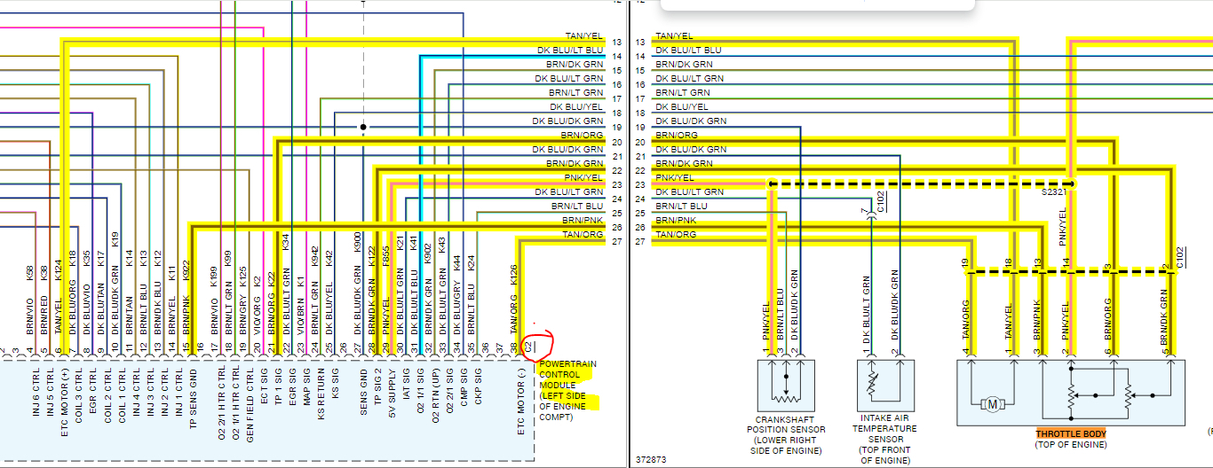
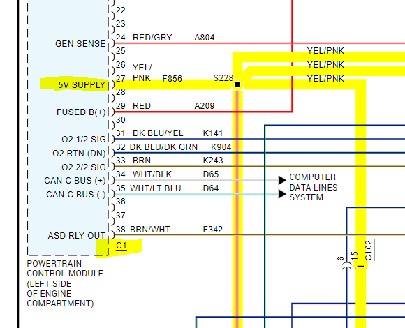
I'm trying to track down a throttle body electrical issue that's triggering the Throttle Control Warning Light. I've had this problem for two years and I believe it's a wiring issue with either the C1 or C2 connector that connects to the TIPM.
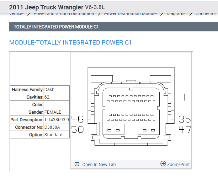
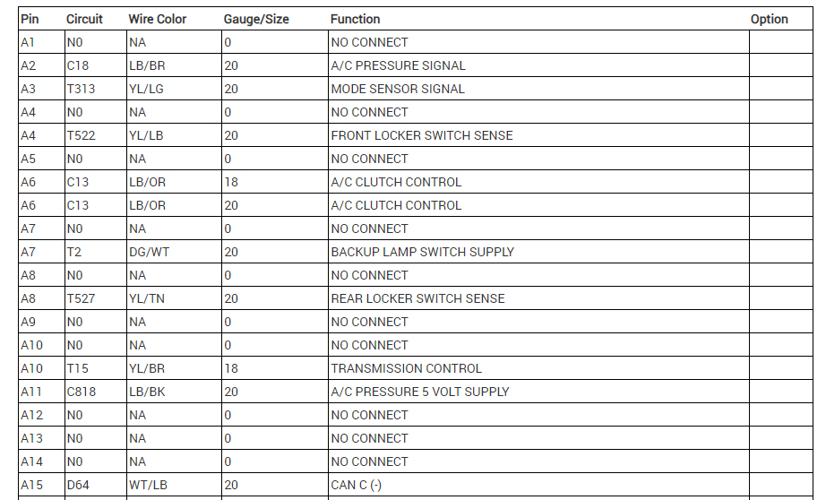
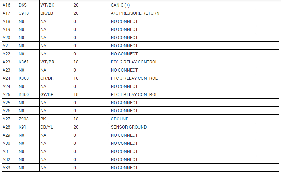
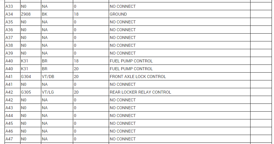
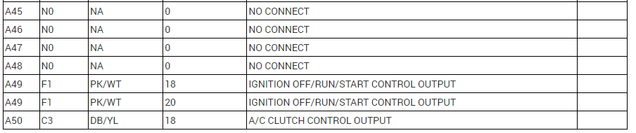
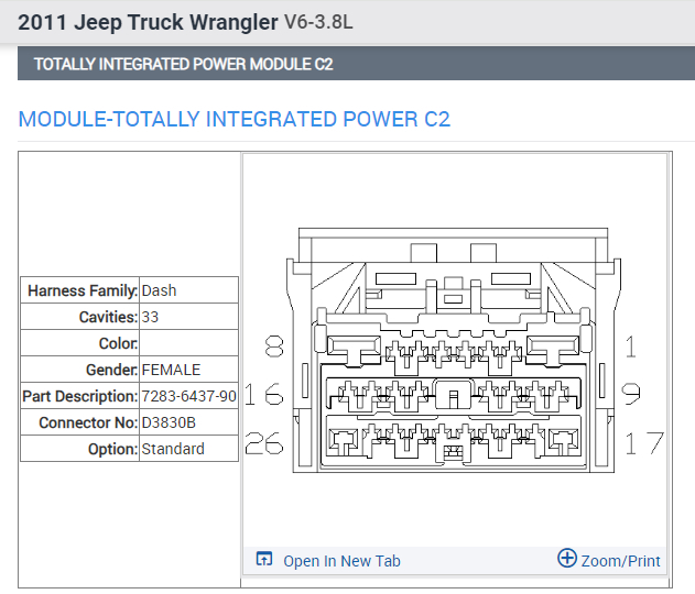
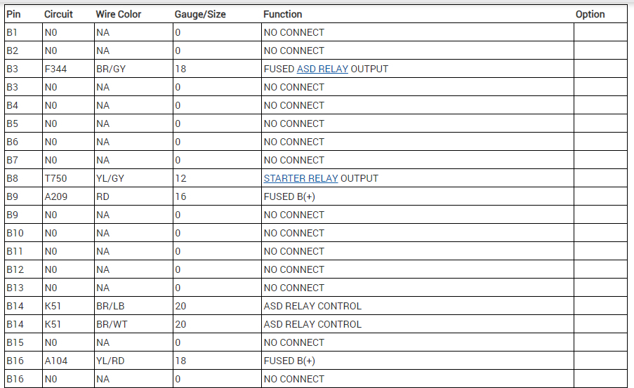
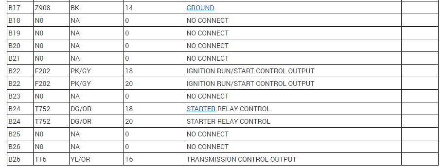
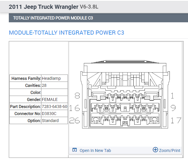
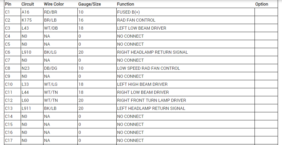
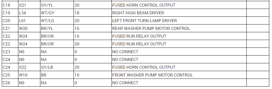
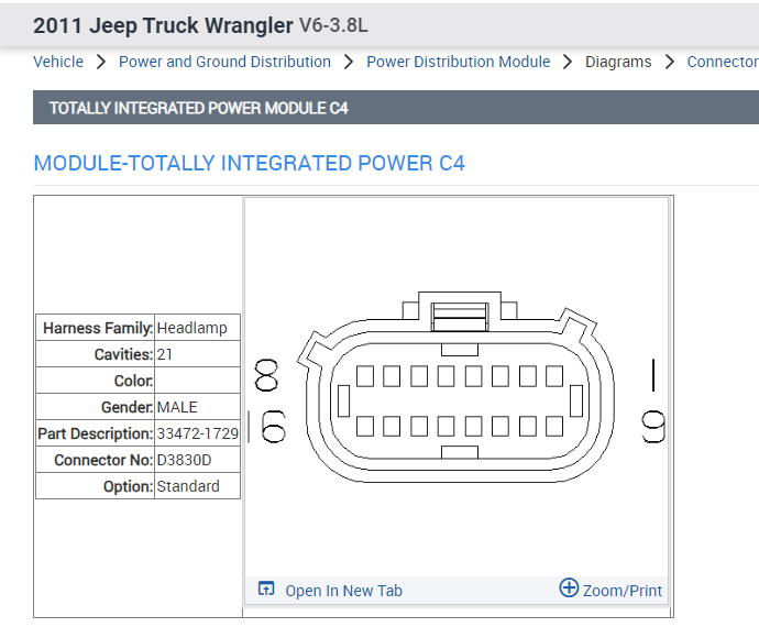
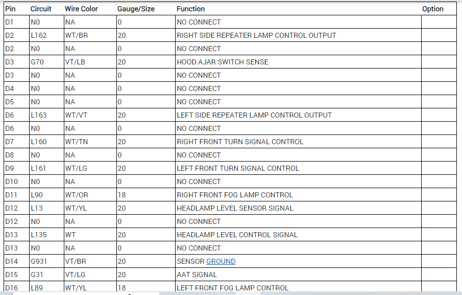
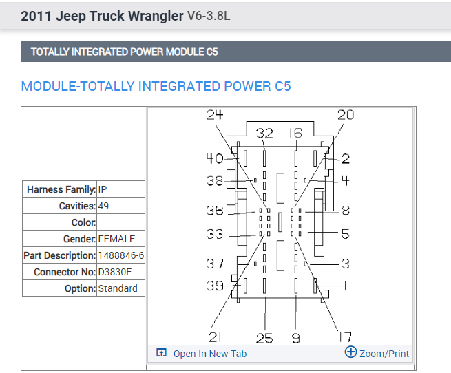
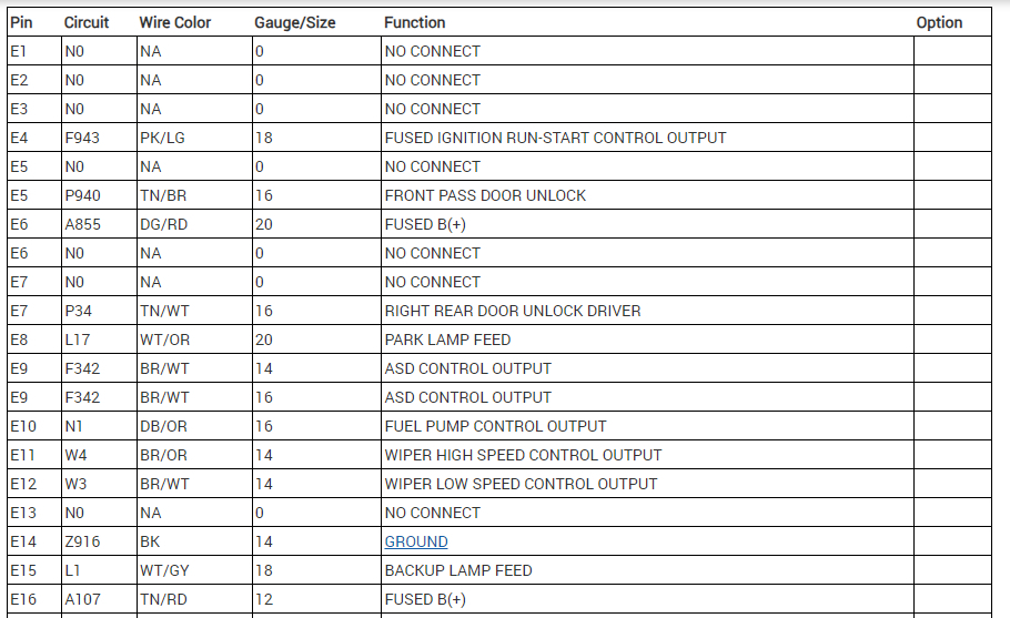
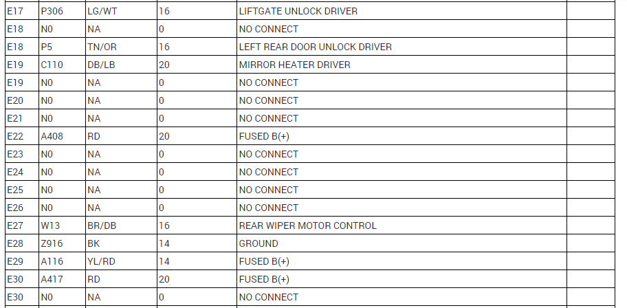
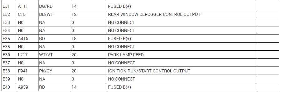
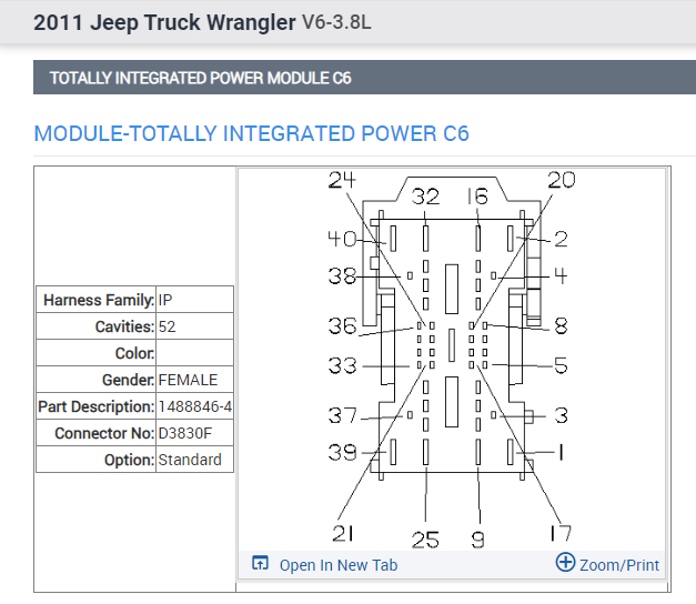
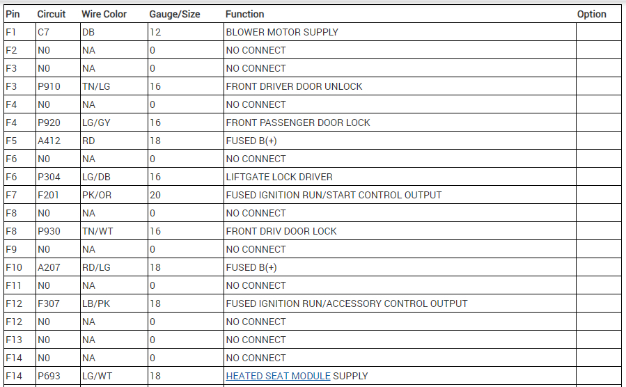
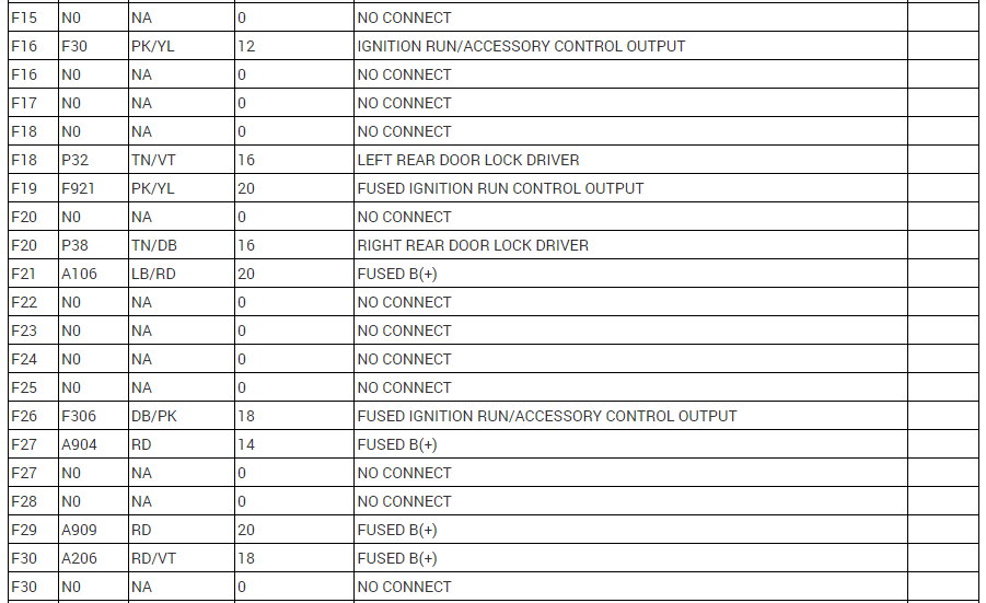
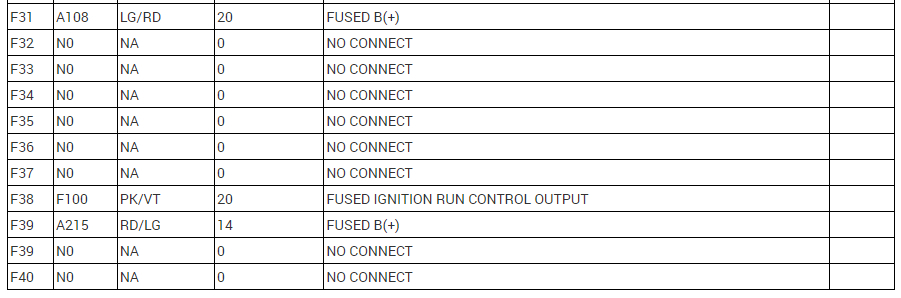
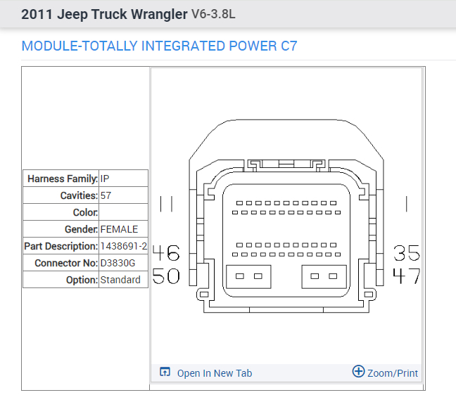
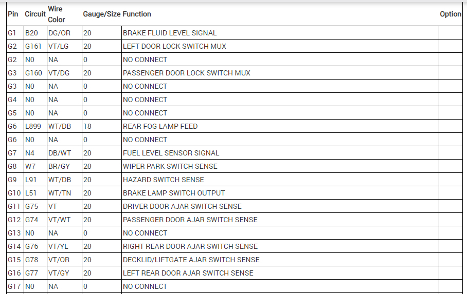
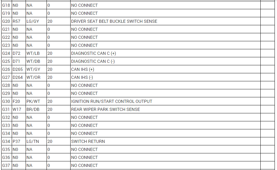
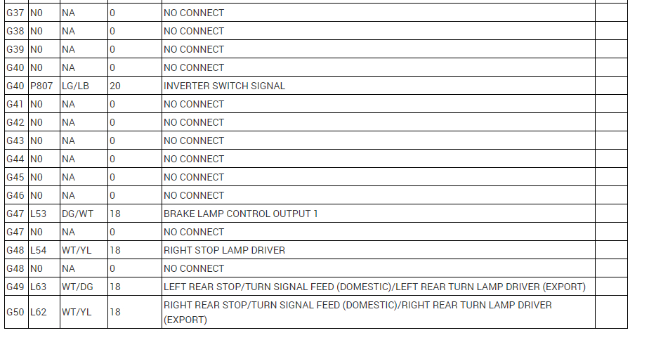
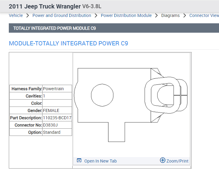
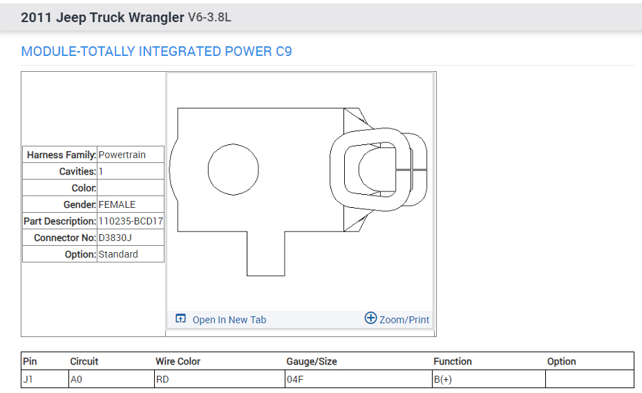
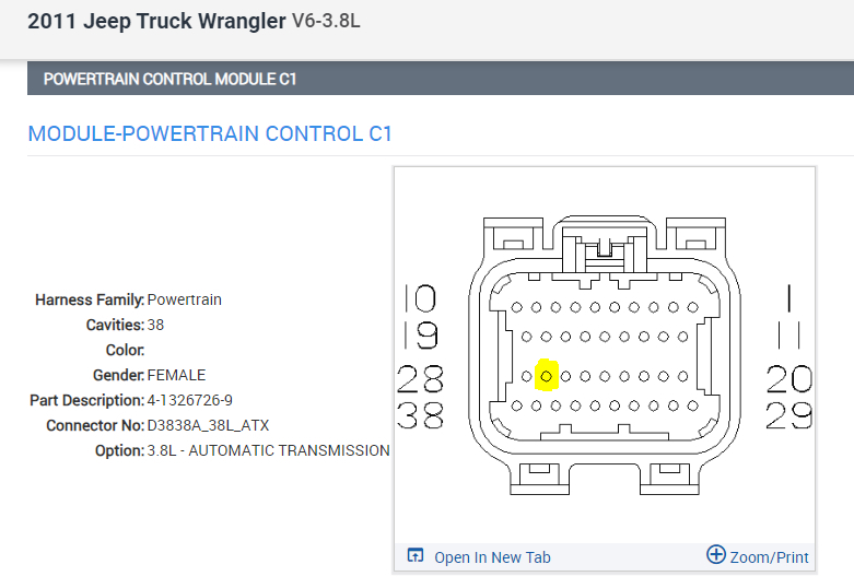
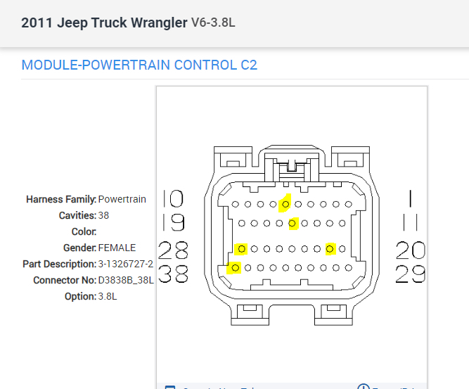
I would like pinout diagrams of all of the "C" (C1-C7) connectors that attach to the bottom of the TIPM.
Jan 30, 2024 at 4:02 PM
Advertisement
Avatar
JACOBANDNICKOLAS
  • CERTIFIED EXPERT
  • 110,175 POSTS
Hi,

I attached the connector views and the pinout information below for all the TIPM connectors. For each connector, the first pic is the connector itself and the following pics are what each pin is for.

When you inspect the connector pins, make sure none are cracked or corroded. I have experienced more times than one wire that shows proper voltage until it is under a load and then it drops off. In most cases, the connector pin is either cracked or corroded.

Take a look through the pics and let me know if you have any questions.

Take care,

Joe

See pics below.
Jan 30, 2024 at 9:09 PM
Avatar
GEOFF LEGLER
  • MEMBER
  • 3 POSTS
Thank you for the TIPM pinouts.

I don't see any pins that that are marked as throttle body control.

Do you know if any of the circuits going in or out of the TIPM would cause a P2138 fault code (Throttle/Pedal Position Sensor/Switch D/E Voltage Correlation)?

Note: I've changed the TB (twice), the gas pedal, the TB wire harness, the TIPM and the ECM. The fault is sporadic and may come on 3 times in a day or not at all for weeks.
Feb 1, 2024 at 10:18 AM
Advertisement
Avatar
JACOBANDNICKOLAS
  • CERTIFIED EXPERT
  • 110,175 POSTS
Hi,

All wires from the throttle body go to the PCM (C2) except one (see pic 2 below). It is a yellow wire with a pink tracer. It goes to the accelerator pedal position sensor and from there runs to connector 1 (C1) at the PCM where it receives a 5v power signal. (see pic 1 below) Note: Pin 6 in the C2 also is a voltage signal between the PCM and the throttle body motor.

In C1, pin 27 is the 5v power supply. In C2, pins 6, 15, 21, 28, and 38 are from the throttle body.

Let me know if this helps.

Take care,

Joe

See pics below. Note: I attached the PCM C1 and C2 views and a legend indicating what each pin does.
Feb 1, 2024 at 8:21 PM
Avatar
GEOFF LEGLER
  • MEMBER
  • 3 POSTS
Thank you. I'll take a look at the connectors tomorrow.
Feb 1, 2024 at 8:27 PM
Avatar
JACOBANDNICKOLAS
  • CERTIFIED EXPERT
  • 110,175 POSTS
Happy to help. If you have a chance, let me know how things turn out for you. Also, let me know if I can help.

Joe
Feb 2, 2024 at 9:08 PM