Testing alternator or other component in the charging system

2005 MERCEDES BENZ C230
155,000 MILES • 1.8L • 4 CYL • 2WD • MANUAL
Avatar
KEVIN HENNELLY
  • MEMBER
  • 1 POST
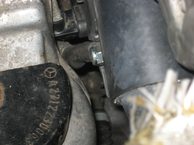
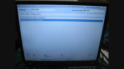
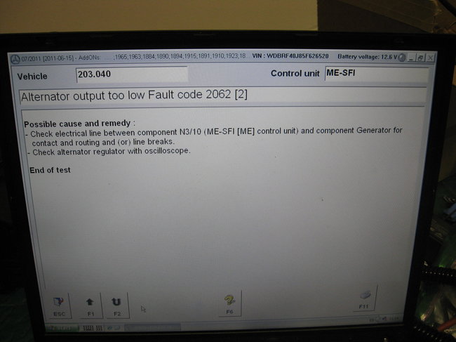
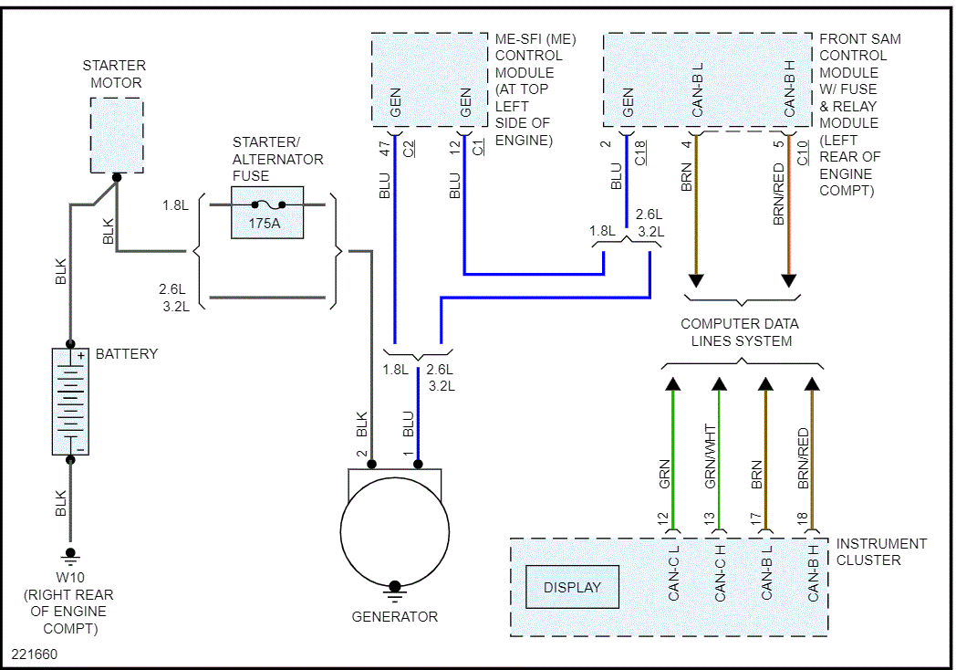
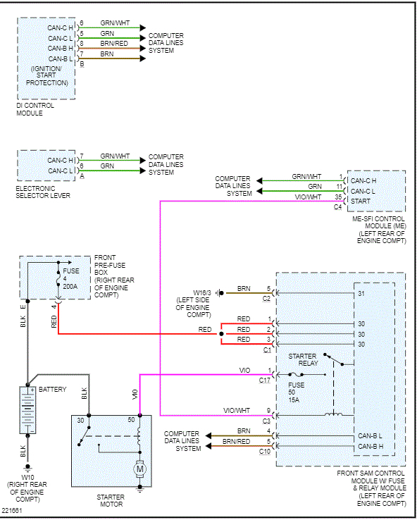
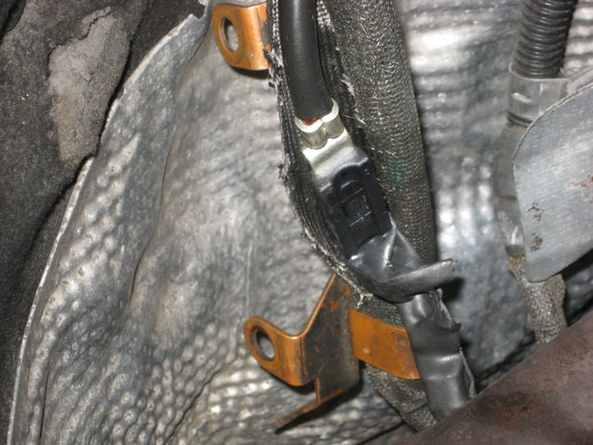
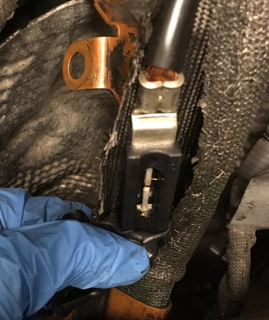
I dropped a wrench while making a repair. It struck the alternator power connection and the frame causing a short circuit. When I started the car, the battery/alternator warning light illuminated. I checked the voltage with the car running and it is either 12 or 12.1 volts, so the system is definitely not charging.

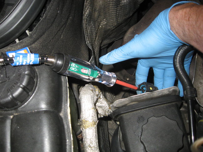
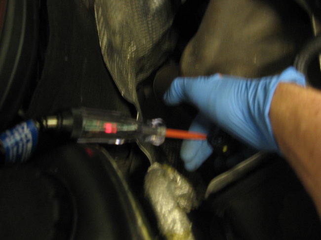
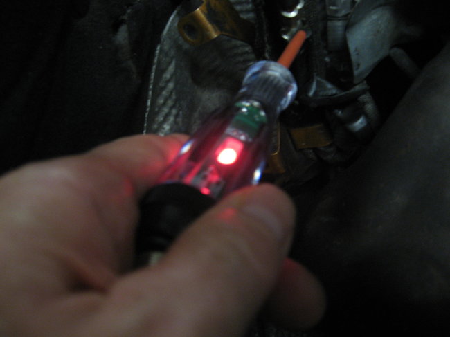
I am trying to determine whether the alternator was damaged by incident or if some other component of the system is causing the problem. I used a voltmeter to perform a diode test and it appears that the diodes were damaged. This is the first time I have worked with a potentially damaged alternator and I am unsure of my testing skills and techniques. I tried to have the alternator tested at two auto parts stores, but the alternator did not fit on their machines correctly and they couldn't run the test.

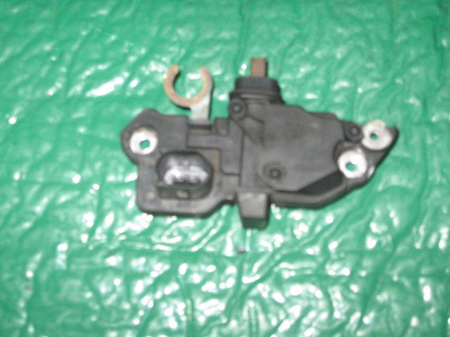
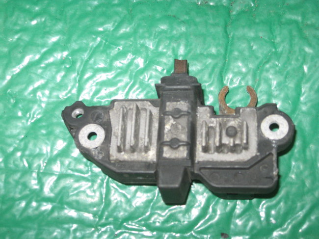
I purchased a used alternator from a recycler and replaced the voltage regulator on it. It passed the diode test that the original alternator failed. Are there any other tests that I can run on the used alternator before installing it in the car? I will try some other parts stores to see if they can test the alternator, but the machines I've seen appear similar and I am not sure I will be able to find someone to test it.
Jun 12, 2020 at 7:54 AM
Advertisement
Avatar
JACOBANDNICKOLAS
  • CERTIFIED EXPERT
  • 110,175 POSTS
Hi,

It sounds like the alternator regulator was damage especially if the diodes are bad. It will need replaced. Even if you get it to charge, the diodes will allow a constant draw on the battery likely draining it overnight.

Here is a link that explains in general how to replace one:

https://www.2carpros.com/articles/how-to-replace-an-alternator

Here is a test for diagnostics. The attached pics indicate directions.

2005 Mercedes Benz C 230 (203.040) L4-1.8L SC (271.948)
AR15.40-P-5000P Test Alternator and Regulator
Vehicle Starting and Charging Charging System Voltage Regulator Testing and Inspection Component Tests and General Diagnostics AR15.40-P-5000P Test Alternator and Regulator
AR15.40-P-5000P TEST ALTERNATOR AND REGULATOR
AR15.40-P-5000P Test alternator and regulator

Component Identification
Pic 1
Steps 1-4
pic 2

Commercially available tools
pic 3

__________________________

Let me know if I can help.

Joe
Jun 12, 2020 at 10:40 AM
Avatar
KEVIN HENNELLY2
  • MEMBER
  • 22 POSTS
Thanks for the reply. You posted a YouTube video showing how to replace the alternator on a C230 and it was extremely helpful. I removed the original alternator that I thought I damaged with the wrench and took it for a test. The person who ran the test said it was a good alternator, but I don't have any specific data. With the alternator disconnected from the car, the diode test provided a different result. Now, I'm not sure the problem is the alternator itself. Could I have damaged some wiring or another component?
Jun 12, 2020 at 4:37 PM
Advertisement
Avatar
KEVIN HENNELLY2
  • MEMBER
  • 22 POSTS
Fortunately, I have access to a Star diagnostic and I will run the test you suggested tomorrow.
Jun 12, 2020 at 4:38 PM
Avatar
JACOBANDNICKOLAS
  • CERTIFIED EXPERT
  • 110,175 POSTS
Hi,

Anything is possible. I attached a picture of the wiring schematic for the charging system. Since the starter is working, I assume the starter/alternator fuse (175 amp) is okay, but check it anyway.

Also, there should be a black wire at the alternator. Check to make sure it is getting power.

Let me know.

Joe
Jun 12, 2020 at 11:24 PM
Avatar
KEVIN HENNELLY2
  • MEMBER
  • 22 POSTS
The diagram is helpful. I ran a scan with the STAR tool and the system returned code 2062-002 - Alternator serial interface. No connection to the control module
N3/10 (ME-SFI [ME] control unit)

Based on your diagram, this seems to suggest that there was:

1. Damage to the blue wire that attaches to the control module .
2. (Worse case scenario) a damaged control module.
3. Damaged connector to the alternator.
4. Damaged voltage regulator on the alternator itself since this attaches to the blue wire.

Do you think I am on the right track?
Jun 13, 2020 at 9:33 AM
Avatar
JACOBANDNICKOLAS
  • CERTIFIED EXPERT
  • 110,175 POSTS
Yes, it sounds like you are on the right track. With this code, it is usually the regulator unless the wire was damaged between the ME-SFI control module and the alternator. Was there any damage to the wires when you were working on it? Also, since you are getting the code, I don't think it's the control module. I suspect it's the regulator or the blue wire you referred to was disconnected or broken somehow.

Let me know.

Joe
Jun 13, 2020 at 7:22 PM
Avatar
KEVIN HENNELLY2
  • MEMBER
  • 22 POSTS
Thanks. It is good to hear that damage to the control module is a less-likely scenario. I couldn't see any damage to the connector or the wires. I'm planning to buy a new voltage regulator and see whether that fixes the problem.

In initially thought it was the voltage regulator. I removed the alternator from the car and had it tested. The test showed it was okay, but I've since found several resources that suggest that the bench test cannot detect issues that are vehicle specific such as communication between the control module and voltage regulator. I don't like to "throw parts at a problem" and a Bosch voltage regulator is $74.00. However, I think I have enough information to justify making the investment and seeing if that works. I'll update the post after I install the new voltage regulator.

I appreciate your time and expertise.
Jun 14, 2020 at 8:06 AM
Avatar
JACOBANDNICKOLAS
  • CERTIFIED EXPERT
  • 110,175 POSTS
Here are the directions for replacing the regulator. The attached pic correlates with the directions.

____________________________________

2005 Mercedes Benz C 230 (203.040) L4-1.8L SC (271.948)
AR15.40-P-5760P Remove/Install Regulator of Alternator
Vehicle Starting and Charging Charging System Voltage Regulator Service and Repair Procedures AR15.40-P-5760P Remove/Install Regulator of Alternator
AR15.40-P-5760P REMOVE/INSTALL REGULATOR OF ALTERNATOR
Remove/Install Regulator Of Generator


pic 1


DANGER:
1.Lethal injuries are possible if vehicle slips off of lifting platform
- Align vehicle between the columns of the lifting platform and position the four support plates at the lifting platform support points specified by the vehicle manufacturer.

2.Risk of explosion from explosive gas. Risk of poisoning and caustic burns from swallowing battery electrolyte. Risk of injury through burns to skin and eyes from battery acid or when handling damaged lead-acid batteries
- No fire, sparks, naked flames or smoking.
- Wear acid-resistant gloves, clothing and goggles. Pour battery electrolyte only into suitable and appropriately marked containers.

1 Disconnect ground cable of battery
2 Remove generator (G2)
3 Unscrew collared nut (2)
4 Unscrew nut (3)
5 Unscrew cover bolt (4)
6 Remove cover (1)
7 Unscrew bolts (6) of regulator (6)
8 Remove regulator (5) towards the side

NOTE: Installation: Do not damage carbon brushes

9 Install in the reverse order

__________________________________________

I hope this helps.

Take care,
Joe
Jun 14, 2020 at 5:22 PM
Avatar
KEVIN HENNELLY2
  • MEMBER
  • 22 POSTS
I replaced the voltage regulator. Unfortunately that didn’t resolve the issue.

I took a second look at the connector and the blue wire and I could not see any damage. I cannot see more than a few inches of the blue wire and I cannot rule out that is damaged in a spot I cannot see. Another potential problem is that some other component in the alternator is damaged and the test equipment at the auto parts store is not detecting it.

I would be willing to replace the entire alternator if I am able to rule out all other potential sources for the problem.
Jun 18, 2020 at 8:59 PM
Avatar
JACOBANDNICKOLAS
  • CERTIFIED EXPERT
  • 110,175 POSTS
Kevin:,

Mercedes is very secretive with info, so the only way I can provide specific test is to know if there is a diagnostic trouble code present.

Is there anyway for you to check right at the alternator for output rather than doing it at the battery?

Joe
Jun 18, 2020 at 9:15 PM
Avatar
KEVIN HENNELLY2
  • MEMBER
  • 22 POSTS
I will check when I arrive home tonight. Thank you for the suggestion.
Jun 19, 2020 at 4:05 AM
Avatar
JACOBANDNICKOLAS
  • CERTIFIED EXPERT
  • 110,175 POSTS
Sounds like a plan. Let me know what you find.

Joe
Jun 19, 2020 at 8:49 AM
Avatar
KEVIN HENNELLY2
  • MEMBER
  • 22 POSTS
I am planning to attach one wire to the alternator and a second to the negative battery terminal. I will attach both of these wires to my multi-meter. Will that yield the reading I need?
Thanks
Jun 19, 2020 at 9:31 AM
Avatar
JACOBANDNICKOLAS
  • CERTIFIED EXPERT
  • 110,175 POSTS
As long as you attach to the output, yes. Actually, you should be able to attach right at the battery wire at the alternator.

Just be careful.

Joe
Jun 19, 2020 at 6:14 PM
Avatar
KEVIN HENNELLY2
  • MEMBER
  • 22 POSTS
Thanks again for your reply. I checked the voltage at the alternator and it was negligible - approximately 0.4 volts. I connected the STAR system and it read the same fault code I posted previously - 2062-002 - Alternator serial interface. No connection to the control module. When I ran the STAR system, there were menu choices for alternator testing, but they would not run on my system. (I bought the system used and I don't know much about its origins. It may be a Chinese clone.) I've posted a video showing what happens when I attempt to use the alternator diagnosis menu. If you pause it at about the half-way point you should see a message that says, "DAS and WIS are active at the same time. It is possible to switch over between the systems with the key combinations ALT + TAB." I'm not sure whether doing that will allow the test to run, but I will give it a try later.

I've also posted photos showing the data connector and the battery connector to the alternator and the voltage regulator that I removed. I cannot see any visible damage.

I think the problems could be:

1. Damage to another part of the alternator.
2. Damage to the communication system between the ECU and the alternator which is preventing the alternator from receiving a signal to turn on.

I was thinking of buying this: https://www.harborfreight.com/Computer-Safe-Automotive-Logic-Probe-63597.html and using it to probe the connection from the ECU to the alternator. My thought process is that it will show whether there is a signal coming from the ECU.

If the alternator is indeed damaged, it appears that buying a rebuilt alternator is the best option. Before I do that I would like to rule out the other possible causes.
Jun 20, 2020 at 8:49 AM
Avatar
JACOBANDNICKOLAS
  • CERTIFIED EXPERT
  • 110,175 POSTS
I watched the video. That jumps around really fast. After the 4th or 5th try, I got it paused so I could read it. LOL

Try what it is saying. The system seems to be glitching for some reason. As far as the start of this issue, I wouldn't think there is a break down in communication. I have a feeling it's the alternator itself, but testing will tell for sure.

Let me know.

Joe
Jun 20, 2020 at 9:14 PM
Avatar
KEVIN HENNELLY2
  • MEMBER
  • 22 POSTS
Thanks for the reply.

Unfortunately hitting alt and tab didn't do anything. I did find another menu (see photo) that suggested (1) checking the communication line between the alternator and the control unit for a break or short and (2) checking the regulator (assuming it means voltage regulator) with an oscilloscope. Because I replaced the voltage regulator (and I don't have an oscilloscope) I will try to figure out how to check the communication line.
Jun 21, 2020 at 8:30 AM
Avatar
KEVIN HENNELLY2
  • MEMBER
  • 22 POSTS
I used a test light to determine whether there was connectivity between in the data wire from the ECU to the alternator. It may be hard to see in the photos, but the LED in the test light is glowing red indicating it has power. I don't know whether it is sending the correct data to the alternator when the system is on, but I guess there are no breaks in the wire. I also cannot see any damage to the part of the wire that is visible or to the connector.

On a different but related topic, I'm wondering whether something wasn't installed on my STAR system. It does not have an icon for the WIS.
Jun 21, 2020 at 9:35 AM
Avatar
JACOBANDNICKOLAS
  • CERTIFIED EXPERT
  • 110,175 POSTS
It looks like the communication is open so that wire isn't the cause. The last thing is the alternator. I suspect there must have been internal damaged done (somehow) to the alternator. Nothing else makes sense. Also, in your original post, you indicated you tried to have it tested at two different parts stores but it wouldn't fit their machine. Is that correct? Is there any reliable shops in the area that would test it for you? For example, a place that deals specifically with auto electrics?
Jun 21, 2020 at 8:50 PM
Avatar
KEVIN HENNELLY2
  • MEMBER
  • 22 POSTS
I first tried a specialist alternator/starter rebuild shop. He said that he didn’t work on Bosch because he couldn’t get parts. (He had piles of starters and alternators most of which appeared large enough to be from commercial vehicles). His test machine was in a dark corner of his shop. I didn’t get a close look at it, but it appeared old and rudimentary. He said he thought the alternator was good, but he didn’t provide any details regarding how he reached that conclusion.

I had also purchased a Valeo alternator from a recycler. I took that to two auto parts stores and they couldn’t fit it on their test machines. I later brought the Valeo alternator to an Advance Auto store. That store had the correct adapter mechanism and belts and could test the Valeo alternator. The technician told me it was defective and I returned it for a refund.

I am planning to take the Bosch alternator to the Advance Auto with the functioning equipment and have it tested. Their equipment seems newer than the machine I saw at the specialist shop and it may provide more detailed information about the Bosch alternator.
Jun 21, 2020 at 9:45 PM
Avatar
KEVIN HENNELLY2
  • MEMBER
  • 22 POSTS
I received a tip on one of the Mercedes forums. There is a fusible link in the starter-alternator wiring loom. I used my test light to check the alternator terminal with the alternator disconnected. There was no power.

I am going to have the alternator tested again tomorrow. If the test shows it is good, I will be turning my focus to the fusible link. Unfortunately it is not in a readily accessible location. I will be studying starter removal procedures on the M271 engine for clues on removing the starter cable.
Jun 22, 2020 at 8:35 PM
Avatar
JACOBANDNICKOLAS
  • CERTIFIED EXPERT
  • 110,175 POSTS
Here are the directions for starter removal and install. Actually, the attached pics include the directions.

___________________

2005 Mercedes Benz C 230 (203.040) L4-1.8L SC (271.948)
AR15.30-P-7100Q Remove Starter, Install
Vehicle Starting and Charging Starting System Starter Motor Service and Repair Removal and Replacement AR15.30-P-7100Q Remove Starter, Install
AR15.30-P-7100Q REMOVE STARTER, INSTALL
Remove starter, install

See attached pics

___________________

pic 10 is the charging system schematic. Pic 11 is the starting system schematic.
Jun 22, 2020 at 10:38 PM
Avatar
KEVIN HENNELLY2
  • MEMBER
  • 22 POSTS
Thanks for the instructions. I would not have been able to remove the battery/starter/alternator cable without them.

Once I had the bolt off, I was able to pull it over the bell housing.  I had to open up the protective casing to access the 175-amp fusible link.  Then, I verified that the link had blown with my test light.  The battery side of the link had power. The other side did not.

Unfortunately, it does not appear that a replacement link can be swapped in.  I searched on the term "175-amp fusible link" and couldn't find anything that looked like the one in the car.  The fusible links that my search identified had different configurations.  It looks like the one Mercedes used was crimped on using a machine that could generate a significant amount of force.

I want the repair I make to be reliable. Although I can find 175 amp fusible links, they look different than the one in the car. (See photos.)

 If I use a fusible link like the one I can buy in an auto parts store, I need to find a way to install that won't allow it to come loose over time.  A better option may be to replace the entire cable with one from a recycling yard.  I have access to a C230 that I used to harvest replacement parts.  Unfortunately, it is sitting on flat tires in the owner's back yard.  To remove the bolt on the starter, I must get under the car and I cannot think of a safe way to do that. 

I found one on an auction site for a coupe, but the listing doesn't confirm that the cable will fit a sedan.  I may take a chance and buy it anyway.

I will appreciate any suggestions.
Jun 27, 2020 at 5:38 PM
Avatar
JACOBANDNICKOLAS
  • CERTIFIED EXPERT
  • 110,175 POSTS
I agree with your thoughts on it coming loose. Have you searched any salvage yards near you? Can you get one from a dealer that won't require you to refinance your home?

Joe
Jun 27, 2020 at 9:20 PM
Avatar
KEVIN HENNELLY2
  • MEMBER
  • 22 POSTS
Thanks again for your help. I appreciate the benefits of a second opinion from a more knowledgeable person. I'd like to have the car back on the road soon, but I need to be patient and do the job right the first time. Unless I'm positive that I can make a reliable repair to the existing harness, I plan to replace it.

I checked the local "Pick and Pull" and they don't have a 2003-2005 C Class with a four cylinder engine listed on their inventory.

I plan to call the other yards on Monday to check whether they can sell the harness. I'm concerned that their business model may be to remove the parts they know they can sell easily and then crush what they don't think they need.

I will also contact the dealer. They are willing to price match the on-line sellers. The challenge with this part is that when I searched a couple of on-line sellers for the part number (A203 540 0530) their web sites show that the part has been superseded by a different part number. Unfortunately the illustration for the new part shows only a cable that runs from the battery to the pre-fuse block.

Jun 28, 2020 at 5:43 AM
Avatar
KEVIN HENNELLY2
  • MEMBER
  • 22 POSTS
I looked more closely at the fusible link assembly.  There was a small cover that I could remove. I have attached a photo of the fusible link. The photo verifies that the link is blown

Does anyone have any ideas about (1) how to replace the link and (2) where can I find the replacement 175-amp link?
Jun 28, 2020 at 8:12 AM
Avatar
KEVIN HENNELLY2
  • MEMBER
  • 22 POSTS
I may have had two problems and only solved one.

I installed the new battery/starter/alternator cable. (If anyone else ever needs to do this, the instructions Jacob and Nickolas posted are great.) There are also videos on YouTube. The cable has to fit between the starter and the engine block or the cable end will block the re-installation of the supercharger dampener. Look at the routing of the cable as you remove it, and you will see how to do it. It may be easier to route the cable if you remove the starter. I did not remove the starter because I couldn't remove one of the bolts holding it in place due to the size of the head of my ratchet. If I have to replace the starter, I will need to buy a ratchet with a more compact head or use a combination of a swivel and extensions to access it. I saw some people claim that they did not need to remove the supercharger dampener to access the bolt holding the cable on the end of the starter. I don't see how they did that. In addition to the dampener, I had to disconnect the steering linkage and move a refrigerant line.

To make a long story short, I now have power to the alternator. Unfortunately, I still have the alternator-battery warning light. When I display the voltage on the center information screen with the car running it shows 12.1 volts instead of the 14-14.2 volts it would display before I damaged the system.

When I connect the STAR tool, it displays the same fault code as it did before I replaced the cable - 2062-02-Alternator Serial Interface - No connection to the control module. As noted in previous posts, the data line to the ECU has continuity. However, I have not used an oscilloscope (as someone on another forum suggested) to read the data.

I had previously had the alternator tested at a rebuild shop on a somewhat primitive looking machine. The technician gave it a passing grade. I replaced the voltage regulator on it because the brushes were worn. I had it retested at an Advance Auto and they said it failed. The Advance Auto test machine is capable of printing out data, but the technician didn't know how to do it. He did tell me the voltage regulator was okay.

It looks like my next step may be to replace the alternator with a rebuilt unit. Before I spend $200.00 throwing another part at the car, does anyone have other suggestions? I think my second option would be to follow the advice I received on another forum and either obtain an oscilloscope to read the data or find someone who has the equipment and can do it for me.
Jul 2, 2020 at 7:06 PM
Avatar
JACOBANDNICKOLAS
  • CERTIFIED EXPERT
  • 110,175 POSTS
Honestly, you have done a lot of work. Other than checking with an oscilloscope, there really is nothing else to check. Is there a different parts store that could confirm what AZ told you?
Jul 3, 2020 at 10:38 PM
Avatar
KEVIN HENNELLY2
  • MEMBER
  • 22 POSTS
I replaced the alternator with a new Bosch unit. Unfortunately, that didn’t repair the problem. I understand that there could be a manufacturing defect in the new alternator, but that seems like a low probability event. I may need to take the car to a shop unless there are other options to consider.
Jul 7, 2020 at 9:19 PM
Avatar
JACOBANDNICKOLAS
  • CERTIFIED EXPERT
  • 110,175 POSTS
The only thing I have is what is related to the code that you found originally. Here is what is listed:

__________________________________

2005 Mercedes Benz C 230 (203.040) L4-1.8L SC (271.948)
Test 1: Alternator Output Too Low Fault Code 2062 [2]
Vehicle ALL Diagnostic Trouble Codes ( DTC ) Testing and Inspection Manufacturer Code Charts Powertrain Management Code Tests 2062 [2] Alternator Serial Interface: No Connection to Control Module N3/10 (ME-SFI Control Module) Test 1: Alternator Output Too Low Fault Code 2062 [2]
TEST 1: ALTERNATOR OUTPUT TOO LOW FAULT CODE 2062 [2]
Alternator output too low Fault code 2062 [2]

Possible cause and remedy

- Check electrical line between component N3/10 (ME-SFI control module) and component Generator for contact and routing and (or) line breaks.

- Check alternator regulator with oscilloscope.


___________________________

Joe
Jul 8, 2020 at 8:57 PM
Avatar
KEVIN HENNELLY2
  • MEMBER
  • 22 POSTS
I have made progress, but not achieved complete resolution. Here’s a link to a video showing what happens when I start the car and rev the engine:

https://www.youtube.com/watch?v=n23pGP5JSzA

https://www.youtube.com/watch?v=7exQ_Lnr64M&feature=emb_rel_end

The alternator starts charging and holds a steady voltage reading of 14 volts even after it returns to idle. I have 3 problems:
1. The alternator warning illuminates
2. The fault code for no communication with the control unit remains
3. The voltage should be 13.4 to 13.6 and I am concerned about over charging the system and damaging another component if I run the car for a long time at 15 volts.

I was able to return the new alternator I bought for a refund because the original alternator with the replacement voltage regulator exhibited the same performance.

I confirmed that the wiring between the alternator and the ECU and between ECU and the front SAM is undamaged.

I am wondering whether the front SAM could have been damaged by the short I induced with my wrench. I know that the wiring between the ECU and the alternator and the ECU and the SAM is OK, but the circuit board in the SAM may not have fared as well. I could install a SAM I removed (because of a defective turn signal) in the car. If this fixes the alternator communication problem I understand that I would have to buy another SAM to repair the turn signal issue. I am also wondering whether a damaged SAM might explain the problem I am having with DAS/Xentry. The system has been returning error messages and won’t allow me to run tests consistently.

I may also be starting to grasp at straws. I would appreciate any feedback you can offer.
Jul 28, 2020 at 12:48 AM
Avatar
KEVIN HENNELLY2
  • MEMBER
  • 22 POSTS
I made some progress as you can see in this video:

https://www.youtube.com/watch?v=n23pGP5JSzA

When I rev the engine the alternator starts charging and produces 14 volts even after returning to idle. I have three problems:
1. The alternator warning light continues to illuminate
2. The error code for no communication with the alternator continues to set
3. I confirmed with other C230 owners that 13.4 -13.6 volts is the normal reading and I am concerned that too much voltage may damage a component

I confirmed that there is no damage to the wiring between the alternator and the ECU and between the ECU and the front SAM with a multi-meter.

I am wondering whether the front SAM could have been damaged by the short I induced with my wrench. I know that the wiring between the ECU and the alternator and the ECU and the SAM is OK, but the circuit board in the SAM may not have fared as well. I could install a SAM I removed (because of a defective turn signal) in the car. If this fixes the alternator communication problem I understand that I would have to buy another SAM to repair the turn signal issue. I am also wondering whether a damaged SAM might explain the problem I am having with DAS/Xentry. The DAS/Xentry system has been returning error codes and balks at performing some tests.

I may also be starting to grasp at straws.

Jul 28, 2020 at 1:18 AM
Avatar
JACOBANDNICKOLAS
  • CERTIFIED EXPERT
  • 110,175 POSTS
It is possible for damage to it. Also, the voltages you mentioned and normal. I've seen them over 14 with no issues. Actually, with the engine running and things off, 14 is what I consider to be a target voltage.

Switch the two sam modules and let me know what happens.

I don't know if you need it, but here are the directions for removal and replacement of the front SAM module.

____________________________________

2005 Mercedes Benz C 230 (203.040) L4-1.8L SC (271.948)
AR54.21-P-1260P Remove/Install SAM With Fuse and Relay Box, Left Front
Vehicle Powertrain Management Relays and Modules - Powertrain Management Relays and Modules - Computers and Control Systems Body Control Module Service and Repair Removal and Replacement AR54.21-P-1260P Remove/Install SAM With Fuse and Relay Box, Left Front
AR54.21-P-1260P REMOVE/INSTALL SAM WITH FUSE AND RELAY BOX, LEFT FRONT
AR54.21-P-1260P Remove/Install SAM With Fuse and Relay Box, Left Front


Shown In Model 203.0

Pic 1


DANGER:
- Risk of injury in the form of trapping or crushing, or even severing of limbs, if caught in windshield wiper mechanism
- Always remove ignition key when working on windshield wiper mechanism.

1 Set wiper arms to vertical position

DANGER:
- Risk of explosion from explosive gas. Risk of poisoning and caustic burns from swallowing battery electrolyte. Risk of injury through burns to skin and eyes from battery acid or when handling damaged lead-acid batteries
- No fire, sparks, naked flames or smoking.
- Wear protective gloves, acid-resistant clothing and safety glasses. Pour battery electrolyte only into suitable and appropriately marked containers

2 Disconnect ground cable of battery

CAUTION: Do not connect quiescent current retention unit due to risk of short-circuit.

3 Unlock and remove cover (1) on module housing (4)

NOTE: Installation: Check gasket for damage

4.1Remove injection system control module
4.2Remove front SAM control module with fuse and relay module (N10/1) from guide.
5 Unscrew bolts (3)
6 Release and remove connectors

NOTE:
- At top on front SAM control module with fuse and relay module (N10/1)
- Removal: Disconnect cables from control module and fuse and relay box
- Installation: Connect cables on control module and fuse and relay box

7 Expose wiring harness.
8 Remove front SAM control module with fuse and relay module (N10/1) upwards.

NOTE: Pull out only until connectors are accessible from below.

9 Release and remove connectors

NOTE:
- At top on front SAM control module with fuse and relay module (N10/1)
- Removal: Disconnect cables from control module and fuse and relay box
- Installation: Connect cables on control module and fuse and relay box

10 Remove front SAM control module with fuse and relay module (N10/1).

NOTE: When replacing, the fuse and relay assignment must be inspected.

11 Install in the reverse order
12 Perform basic programming
13 Read diagnostic trouble code memory and erase
14 Check for proper function

_______________________________________

Let me know what you find.

Joe
Jul 28, 2020 at 6:59 PM
Avatar
KEVIN HENNELLY2
  • MEMBER
  • 22 POSTS
finally decided to take the car to the dealer. To make a long story short they decided that the LIN Bus wire between the alternator and the ECU is shorting to ground. They told me that their solution was to replace the engine wiring harness and estimated the cost at $2,400.00. I declined the repair.

You may recall that I tested the wire between the alternator and the ECU and the wire between the ECU and the front SAM and they seemed to have good continuity.

At this stage I can think of three options:

1. I am wondering whether it is possible to run a jumper wire from the ECU to the alternator connector to see whether that solves the problem.
2. If that isn't possible, I expect that I can find someone to replace the wiring harness for less than the $2,400.00 quoted by the dealer.
3. I could just drive the car and see if that works. I'll need to get accustomed to seeing the warning light every time I turn the car on.

I don't want to do anything that further damages the car, but I think I've reached a point where I need to perform a rigorous cost-benefit analysis before I invest any additional money.
Aug 18, 2020 at 6:00 PM
Avatar
JACOBANDNICKOLAS
  • CERTIFIED EXPERT
  • 110,175 POSTS
If you are replacing the entire wire, I don't see why that would be an issue. Is that your plan?

Joe
Aug 18, 2020 at 6:53 PM
Avatar
KEVIN HENNELLY2
  • MEMBER
  • 22 POSTS
Thanks for the reply.  I may be able to scavenge what I need from the C230 I have previously used for parts.  Fortunately I have a lot of experience soldering and if I can find a safe route for the wire I can handle the solder and shrink wrap.  

I know this is a long shot, but I am wondering whether it is worth trying to pull a new wire through the existing harness by attaching the new wire to the damaged one.
Aug 18, 2020 at 8:53 PM
Avatar
JACOBANDNICKOLAS
  • CERTIFIED EXPERT
  • 110,175 POSTS
Kevin,

If you try to pull it through the wiring harness, you will go crazy. I would simply replace it and put it in a wire loom to protect it.
Aug 18, 2020 at 8:59 PM