Temperature gauge not working A/C blowing hot

2007 PONTIAC G6
200,000 MILES • 3.4L • 6 CYL • 4WD • AUTOMATIC
Avatar
RUDYNOHUXTABLE
  • MEMBER
  • 1 POST
My temperature gauge was working fine yesterday. I didn't notice it until first break today. i ran my car the whole break and it didn't move at all. It is not the thermostat because the fluid is cycling through my engine. it is not the radiator because the fluid has not leaked out. I just really want to know what it could be. also when i turned my A/C on i noticed it is blowing hot .i added coolant but no change.
Sep 27, 2019 at 9:22 AM
Advertisement
Avatar
STRAILER
  • CERTIFIED EXPERT
  • 53,855 POSTS
Hello,

If the temperature sensor is not working or the computer is having an issue the A/C will not engine because the PCM thinks the engine is overheating. A new temperature sensor can help, but lets start by running the codes to see what comes up. here is a guide to help us get started, the temperature sensor location is in the diagrams below.

https://www.2carpros.com/articles/checking-a-service-engine-soon-or-check-engine-light-on-or-flashing

Check out the diagrams (below). Please let us know what happens.

Sep 29, 2019 at 11:06 AM
Avatar
ZAKARI SOLOMON
  • MEMBER
  • 0 POST
That worked! thank you.
Nov 12, 2020 at 10:41 AM
Advertisement
Avatar
DANE JOHNSON
  • MEMBER
  • 1 POST
My check engine light came on the other day and soon after my temperature gauge stopped working. After i drive the car for a while and feel the engine, it is not hot. There is a bit of warmth emitting from it but not much. Does anyone know what could be wrong? and is it bad to drive a car if the engine is running fairly cold?
Nov 12, 2020 at 10:42 AM (Merged)
Avatar
KHLOW2008
  • CERTIFIED EXPERT
  • 41,814 POSTS
Get a scan done to find out what is causing the check engine light to come on. A scan tool would allow you to see the engine temperature, unless if the temperature sensor is bad.

Once engine has been started for a minute or two, it would be okay to drive around even if you feel the engine might be running cold. Overheating on the other-hand would be a cause for concern.
Nov 12, 2020 at 10:42 AM (Merged)
Avatar
64GTO389
  • MEMBER
  • 3 POSTS
Yesterday my check engine light came on and the temperature gauge quit working and the A/C also did not work. I went to local auto parts store and used OBD and reset the problem. I am just wondering what might cause this issue? After resetting the trouble codes everything seem to be fine for now. I am just wondering if this is common on this vehicle?
Nov 12, 2020 at 10:42 AM (Merged)
Avatar
HARRY P
  • CERTIFIED EXPERT
  • 2,292 POSTS
Did you happen to get the trouble code numbers or just clear them?
Nov 12, 2020 at 10:42 AM (Merged)
Avatar
64GTO389
  • MEMBER
  • 3 POSTS
I just cleared them!
Nov 12, 2020 at 10:42 AM (Merged)
Avatar
HARRY P
  • CERTIFIED EXPERT
  • 2,292 POSTS
Well it is kind of hard to armchair it then, but I would say if it went away with simply clearing the codes that it is probably going to be an intermittent problem. Possibly in the wiring to the coolant temperature sensor. If it happens again, get the trouble code number(s) and we will go from there.
Nov 12, 2020 at 10:42 AM (Merged)
Avatar
64GTO389
  • MEMBER
  • 3 POSTS
Thanks will do
Nov 12, 2020 at 10:42 AM (Merged)
Avatar
NICOLEG6
  • MEMBER
  • 6 POSTS
Hi there,

Just looking for advise where to start and what to check.
My temperature gauge on my cluster does not move stays on bottom/cold.
My fans seems to come on only when it is hot it does not always run on.
I had a coolant leak a month ago, added an additive liquid aluminum type and it seemed to seal whatever leak there was. I have not had to add any coolant.
Check engine light has been on since I purchased and was for EVAP sensor.

I had disconnect the wire harness to the engine coolant temperature sensor to see if I could get in there to replace if necessary, reconnected. Then next time I drove the temperature gauge on cluster worked for about an hour.
Nov 12, 2020 at 10:42 AM (Merged)
Avatar
STEVE W.
  • CERTIFIED EXPERT
  • 15,113 POSTS
With your description I would suspect that the harness or connector at the sensor is the issue as it failed not long after the connector was moved. The fans should not run all the time. They are controlled by the engines temperature and AC use. Not a fan of any sealers as they tend to seal more than just the leak they were intended for.
I would remove the connector and check for loose or corroded pins. Also check the harness itself for damage, it does not take much to rub or melt through the wiring. If you have access to a good scan tool that has bi-directional controls many can do a gauge sweep that would show if the gauge itself was okay.
Nov 12, 2020 at 10:42 AM (Merged)
Avatar
NICOLEG6
  • MEMBER
  • 6 POSTS
Thank you so much Steve your help is really appreciated. I do not have access to much or much cash to ask a garage. I will have a look now for anything loose or corroded and have a look at the harness. Would using a digital multi-meter be useful anywhere?
If everything there looks okay is there another step I should take to dig this?
Nov 12, 2020 at 10:42 AM (Merged)
Avatar
STEVE W.
  • CERTIFIED EXPERT
  • 15,113 POSTS
From your description it sounds like the connector. Use your meter and with the connector unplugged the tan wire should be a ground and the yellow wire should have 5 volts on it. The resistor in the ECT changes the 5 volt signal based on temperature and the PCM reads that and determines engine temperature. It then sends a signal through the data bus to the dash telling it to display the temperature. The gauge is a stepper motor that simply moves to the proper point. Those are a common failure item in the older vehicles but the gauge sweep test should show if it works. Many newer cars usually also sweep the gauges at initial key on. If yours moves the gas, speedometer, tachometer, oil, temperature (what ever it has for gauges) when you turn on the key and the others move but the temperature does not then it could be a faulty stepper motor.
Nov 12, 2020 at 10:42 AM (Merged)
Avatar
NICOLEG6
  • MEMBER
  • 6 POSTS
I completely understand thank you for describing everything so well. I will get right to it. Thank you so much for your time and knowledge Steve! Fingers crossed.
Nov 12, 2020 at 10:42 AM (Merged)
Avatar
STEVE W.
  • CERTIFIED EXPERT
  • 15,113 POSTS
I would say to measure the resistance of the thermistor in the sensor but they rarely fail, it is usually the connector or the harness. Please post back with what you find.
Nov 12, 2020 at 10:42 AM (Merged)
Avatar
NICOLEG6
  • MEMBER
  • 6 POSTS
I did not know that about the sensor. I am glad they do not usually fail. Of course I got nervous and bought one but was not sure if it would of fixed the problem. I have got your posts saved and I will get at it tomorrow and get back to you ASAP.
Thank you so much.
Nov 12, 2020 at 10:42 AM (Merged)
Avatar
JIMB2020
  • MEMBER
  • 106 POSTS
Sister came home with the following symptoms:
Clicking engine noise.
Instrument panel temperature gauge remains at 0.

I checked the oil, it was extremely low. The car has been leaking one drop at a time through the main bearing seal (typical). I replaced the oil and filter less than 2 months ago. I added oil and she drove the car. No noise. Engine sounds great- no problem, but the temperature gauge did not move. It got cold today, so I thought she is driving it very short distance to work, it may have not had a chance to warm up. I asked her to take it for a test drive, but the gauge did not move (engine hot). Is there a correlation between the instrument panel gauge gauge and oil level? could the low level before I replenished the oil have cause some sensor to go bad?
Nov 12, 2020 at 10:42 AM (Merged)
Avatar
STEVE W.
  • CERTIFIED EXPERT
  • 15,113 POSTS
What usually happens is the connector gets corroded or the harness starts to fail. Then, "I will replace the sensor". In the process of removing and replacing the sensor the harness gets moved around and the connector is removed and put on the new part and "miracles abound" the widget starts working again. Had to be a bad part. But it was actually the act of moving the wiring that repaired it. That is why most good diagnostics folks start testing without actually touching the component until they are 99% sure that it is in that area. Nothing like trying to write up a repair when you do not know what it was you moved or disconnected that suddenly brought it back. Plus you cannot say "I know it is repaired and will no't cause that problem again".
Nov 12, 2020 at 10:42 AM (Merged)
Avatar
JACOBANDNICKOLAS
  • CERTIFIED EXPERT
  • 110,175 POSTS
Hi,

I doubt the two are related. However, is the engine coolant full? Is the heater working?

If the coolant is full and the heater is working, then we have flow. So, the next thing would be the engine coolant temperature sensor (ECT). Here is a link that shows how in general how one is replaced:

https://www.2carpros.com/articles/coolant-temperature-sensor-cts-replacement

Here are the directions specific to your vehicle. The attached pics correlate with the directions.

________________________

2006 Pontiac G6 V6-3.9L VIN 1
Removal and Replacement
Vehicle Powertrain Management Sensors and Switches - Powertrain Management Sensors and Switches - Computers and Control Systems Coolant Temperature Sensor/Switch (For Computer) Service and Repair Removal and Replacement
REMOVAL AND REPLACEMENT
ENGINE COOLANT TEMPERATURE (ECT) SENSOR REPLACEMENT

REMOVAL PROCEDURE

NOTE: Use care when handling the coolant sensor. Damage to the coolant sensor will affect the operation of the fuel control system.


pic 1

1. Drain the cooling system. Refer to Draining and Filling Cooling System. See: Cooling System > Removal and Replacement
2. Remove the intake manifold cover, if necessary.
3. Disconnect the engine coolant temperature (ECT) sensor electrical connector.
4. Remove the ECT sensor.

INSTALLATION PROCEDURE

NOTE: Replacement components must be the correct part number for the application. Components requiring the use of the thread locking compound, lubricants, corrosion inhibitors, or sealants are identified in the service procedure. Some replacement components may come with these coatings already applied. Do not use these coatings on components unless specified. These coatings can affect the final torque, which may affect the operation of the component. Use the correct torque specification when installing components in order to avoid damage.


pic 2

1. Coat the threads of the ECT sensor with sealer GM P/N 13246004 (Canadian P/N 10953480) or equivalent.
2. Install the ECT sensor.

NOTE: Refer to Fastener Notice.

Tighten the ECT sensor to 20 N.m (15 lb ft).

3. Connect the ECT electrical connector.
4. Install the intake manifold cover, if necessary.
5. Fill the cooling system. Refer to Draining and Filling Cooling System. See: Cooling System > Removal and Replacement

___________________

Let me know if that helps.

Joe
Nov 12, 2020 at 10:42 AM (Merged)
Avatar
NICOLEG6
  • MEMBER
  • 6 POSTS
Hey Steve.

Sorry for delay our wifi has been down.
So yes your right somethings going on with the wiring .
I checked all the fuses and everything is good there. The wiring looks fine. That is the problem I am having. But I tested the resistance on sensor and it is fine. I had bought a new one just in case and put it in too. Still nothing.

Thank you so much for your advice you have me in the right direction
I will use the multi-meter and check wiring again tonight.
Any thoughts on what could be going on?
Nov 12, 2020 at 10:42 AM (Merged)
Avatar
JIMB2020
  • MEMBER
  • 106 POSTS
Joe,

Yes, I checked the heater inside the car right away. It is super hot on high and normal on medium. Coolant level was a bit lower than normal, however. I will add coolant to the reservoir before she drives it in the morning. I will also test the ECT by disconnecting the connector and checking to see if it is the sensor. I will update the status as soon as I get the gauge back to normal.
Nov 12, 2020 at 10:42 AM (Merged)
Avatar
STEVE W.
  • CERTIFIED EXPERT
  • 15,113 POSTS
I would go to the ECM and find those two wires, measure the resistance at the sensor, then measure it at the ECM connection. If the numbers match within an ohm or two you have a good connection and harness. If not then check end to end of each wire.
Nov 12, 2020 at 10:42 AM (Merged)
Avatar
JACOBANDNICKOLAS
  • CERTIFIED EXPERT
  • 110,175 POSTS
Hi,

Sounds like a plan. Please let me know if you have questions or need help with anything.

Take care,
Joe
Nov 12, 2020 at 10:42 AM (Merged)
Avatar
NICOLEG6
  • MEMBER
  • 6 POSTS
Okay excellent.
Thank you so much for your help Steve.
When it is sorted out I will post and let you know.
Thank you!
Nov 12, 2020 at 10:42 AM (Merged)
Avatar
JIMB2020
  • MEMBER
  • 106 POSTS
Hi there, it looks like the temperature issue has returned as the temperature soared into the 90's here in North Carolina. This time, the coolant boiled over and emptied its content on the driveway. I let it cool and refilled and purged the air out. I examined the fan operation, and it isn't coming on when the engine needs it. I tested it with direct voltage, and it worked. I tested all fuses and relays (ECT 15 amps fuse and the two Fans 30 Amps J-Fuses and 3 Fans Main Relays): all are fine. I hooked up Innova 3130 lat, and it gave me 2070 code, 660 code and 2078 code. Is it the ECT? the thermostat? the ECU/PCM? And just exactly what is an "intake manifold tuning stuck open" (660/2070/2078)? Are there 2 intake manifold tunings? Please, explain what I need to do, and how are all these result correlate (if any)?
Nov 12, 2020 at 10:42 AM (Merged)
Avatar
STRAILER
  • CERTIFIED EXPERT
  • 53,855 POSTS
Steve W is one of our best. Please let us know what you find. We are interested to see what it is.

Cheers, Ken
Nov 12, 2020 at 10:42 AM (Merged)
Avatar
JACOBANDNICKOLAS
  • CERTIFIED EXPERT
  • 110,175 POSTS
Hi,

First, the codes are all related. I suspect the tuning valve needs replaced. However, we need to confirm it first.

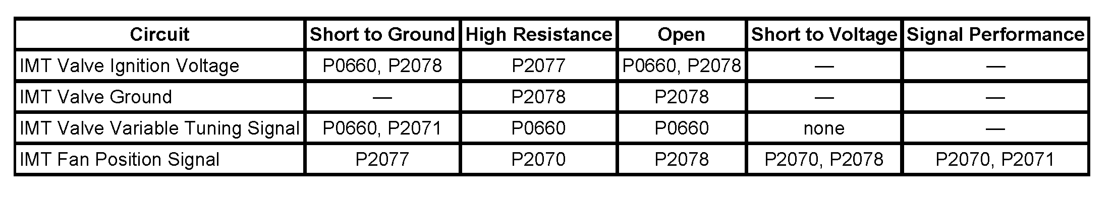
The P0660 relates to the intake manifold tuning valve. An intake manifold tuning (IMT) valve is used to change the intake manifold plenum configuration. When the IMT valve is open, the intake manifold is configured to one large plenum. When the IMT valve is closed, the intake manifold is configured to 2 smaller plenums. The IMT valve improves engine performance at low and high engine speeds depending on the engine load.

As far as the P2070, it indicates the control module detects that the IMT valve is stuck open and the P2078 indicates high voltage to the control valve.

Both of these codes indicate to perform the diagnostics for code P0660 first before continuing. I suspect the tuning valve has shorted and needs replaced, but the test will confirm.

Here is everything related to that code. The two attached pics correlate with this information.

__________________________________________

2006 Pontiac G6 V6-3.9L VIN 1
P0660
Vehicle ALL Diagnostic Trouble Codes ( DTC ) Testing and Inspection P Code Charts P0660
P0660
DTC P0660

DTC DESCRIPTOR

DTC P0660
Intake Manifold Tuning (IMT) Valve Solenoid Control Circuit

DIAGNOSTIC FAULT INFORMATION

IMPORTANT: Always perform the Diagnostic System Check - Vehicle prior to using this diagnostic procedure. See: A L L Diagnostic Trouble Codes ( DTC ) > Testing and Inspection


pic 1


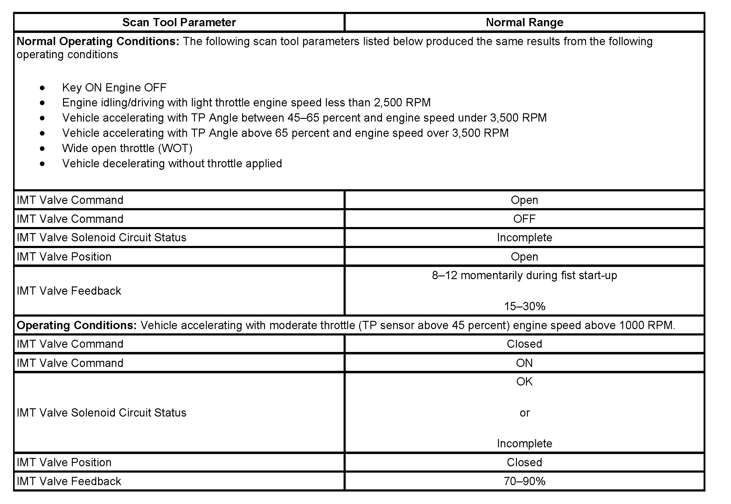
TYPICAL SCAN TOOL DATA


pic 2


CIRCUIT/SYSTEM DESCRIPTION
An intake manifold tuning (IMT) valve is used to change the intake manifold plenum configuration. When the IMT valve is open, the intake manifold is configured to one large plenum. When the IMT valve is closed, the intake manifold is configured to 2 smaller plenums. The IMT valve improves engine performance at low and high engine speeds depending on the engine load. The IMT valve assembly consists of the following:
- A tuning valve
- A microprocessor
- An electric motor
- A hall-effect sensor
- An ignition voltage circuit
- A ground circuit
- A variable tuning signal circuit
- An IMT fan position signal circuit

Ignition Voltage Circuit
An ignition voltage is supplied directly to the IMT valve assembly from the powertrain relay through a 10-amp fuse. The ignition voltage provides power to a microprocessor and to a motor that rotates the IMT valve within the intake manifold.

Ground Circuit
Ground circuit is supplied directly to the IMT valve assembly. This circuit provides ground for the micro-processor and the motor.

Variable Tuning Signal Circuit
During operation when the valve is open the control module applies ground to the variable tuning signal circuit which indicates to the microprocessor within the IMT valve to position the valve to the closed position which turns the motor ON and rotates the IMT valve within the intake manifold plenum.

IMT Fan Position Signal Circuit
When the IMT valve is rotated the hall-effect sensor is reporting the position of the valve to the ECM. The control module uses this feedback signal to determine the position of the IMT valve.

The control module compares the commanded state of the variable tuning signal circuit and compares it to the IMT Fan Position Signal Circuit for being stuck open, stuck closed.

CONDITIONS FOR RUNNING THE DTC
- The engine speed more than 425 RPM.
- The system voltage is between 9-18 volts.

CONDITIONS FOR SETTING THE DTC
The control module detects that the state of the driver and the state of the circuit do not match. The control module will detect an open, short to ground on the variable tuning valve signal or an open or a short to ground on the ignition voltage circuit of the IMT valve solenoid for more than 6.25 second

ACTION TAKEN WHEN THE DTC SETS
- The control module illuminates the malfunction indicator lamp (MIL) when the diagnostic runs and fails.
- The control module records the operating conditions at the time the diagnostic fails. The control module stores this information in the Freeze Frame and/or the Failure Records.
- The control module commands the TAC system to operate in the Reduced Engine Power mode.
- A message center or an indicator displays Reduced Engine Power.
- Under certain conditions the control module commands the engine OFF.

CONDITIONS FOR CLEARING THE MIL/DTC
- The control module turns OFF the malfunction indicator lamp (MIL) after 3 consecutive ignition cycles that the diagnostic runs and does not fail.
- A current DTC, Last Test Failed, clears when the diagnostic runs and passes.
- A history DTC clears after 40 consecutive warm-up cycles, if no failures are reported by this or any other emission related diagnostic.
- Clear the MIL and the DTC with a scan tool.

CIRCUIT/SYSTEM VERIFICATION
Command the IMT valve ON. The IMT Valve Command parameter should transition from open to closed and the IMT Valve Feedback parameter should transition from 15-30 percent to 70-90 percent.

CIRCUIT/SYSTEM TESTING
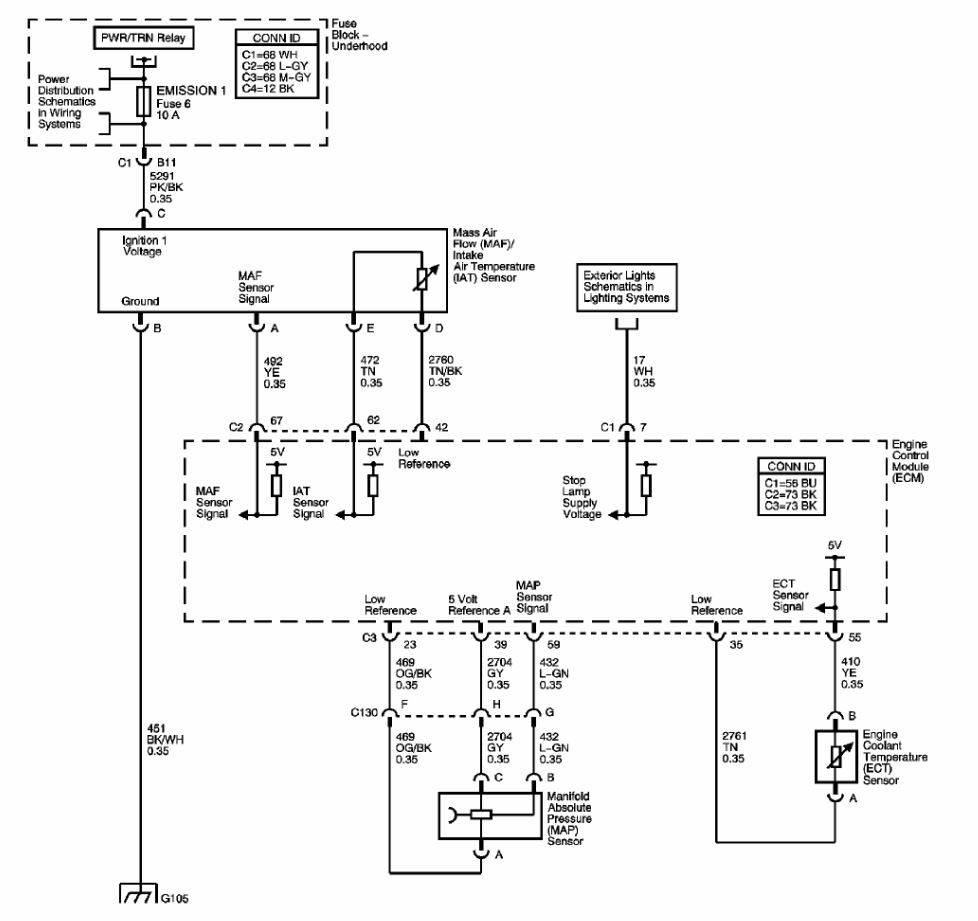
1. Ignition ON, measure for battery voltage between the IMT valve ignition voltage circuit and ground. Battery voltage should be measured.
- If less than battery voltage test the ignition voltage circuit for an open, high resistance or short to ground, if shorted to ground replace the fuse that supplies the voltage.
2. Connect a test lamp between the IMT valve ignition voltage circuit and ground circuit at the IMT valve harness connector. The test lamp should illuminate.
- If The test lamp does not illuminate, test the ground circuit for an open or high resistance.
3. Ignition ON, disconnect the IMT valve harness connector and measure for 0.5 volt on the variable tuning signal circuit and ground.
- If less than 0.5 volt test the variable tuning signal circuit for an open or high resistance, short to ground, or a faulty control module.
- If more than 0.5 volt test the variable tuning signal circuit for a short to voltage or a faulty control module.
4. Measure for 5.0 volts on the IMT fan position signal circuit at the IMT valve harness connector.
- If more than 5 volts, test the IMT fan position signal circuit for a short to voltage.
- If less than 5 volts, test the IMT fan position signal circuit for an open, high resistance, or short to ground.
- If all circuits test OK, replace the IMT valve.

REPAIR INSTRUCTIONS
- Control Module References
- Intake Manifold Tuning Valve Replacement

REPAIR VERIFICATION

IMPORTANT: Always perform the Diagnostic Repair Verification after completing the diagnostic procedure. See: A L L Diagnostic Trouble Codes ( DTC ) > Verification Tests

__________________________________________

If you determine it needs replaced, here are the directions.

_________________________________________

2006 Pontiac G6 V6-3.9L VIN 1
Intake Manifold Tuning Valve Replacement

REMOVAL PROCEDURE


pic 3

1. Remove the intake manifold cover.
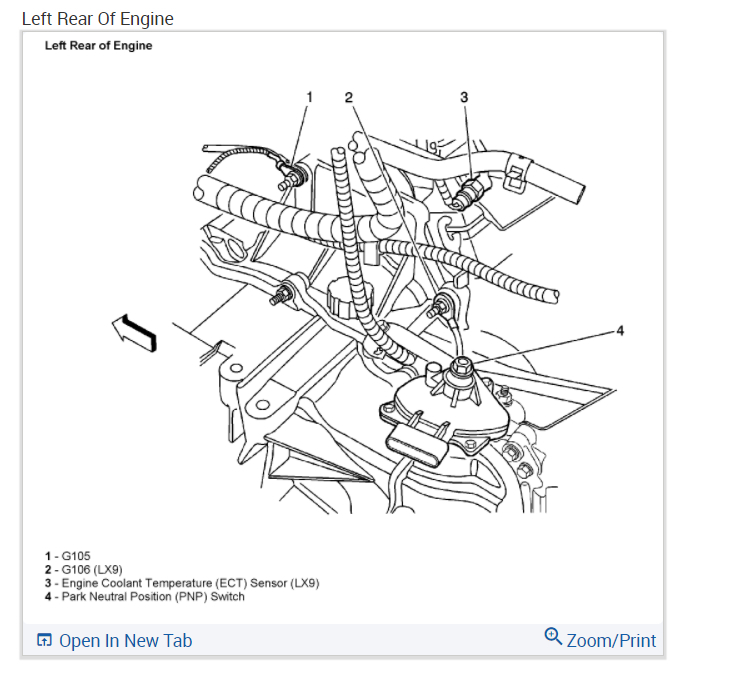
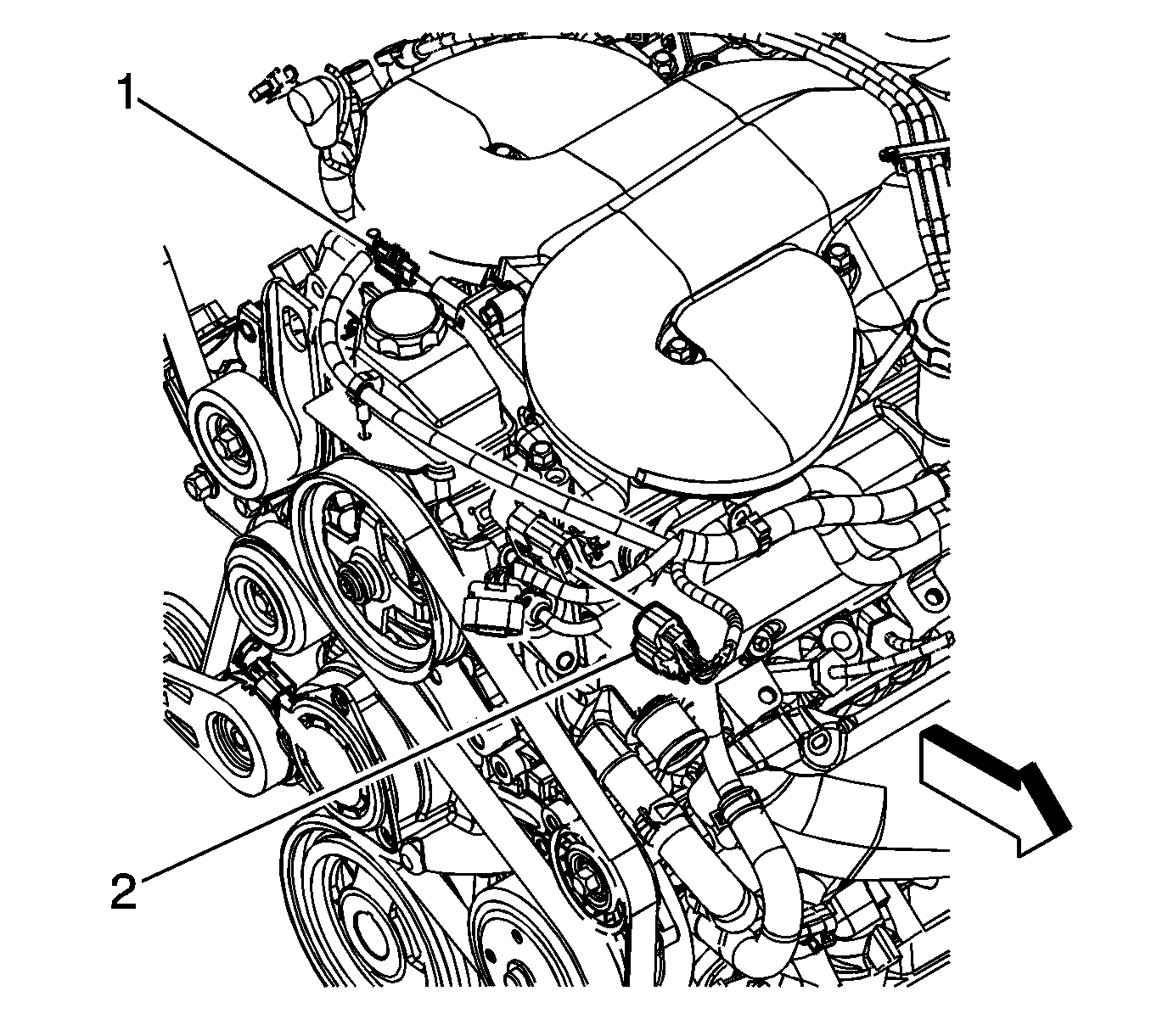
2. Disconnect the intake manifold tuning valve electrical connector (1).
3. Remove the engine harness clip from the power steering reservoir bracket.
4. Remove the power steering pump.
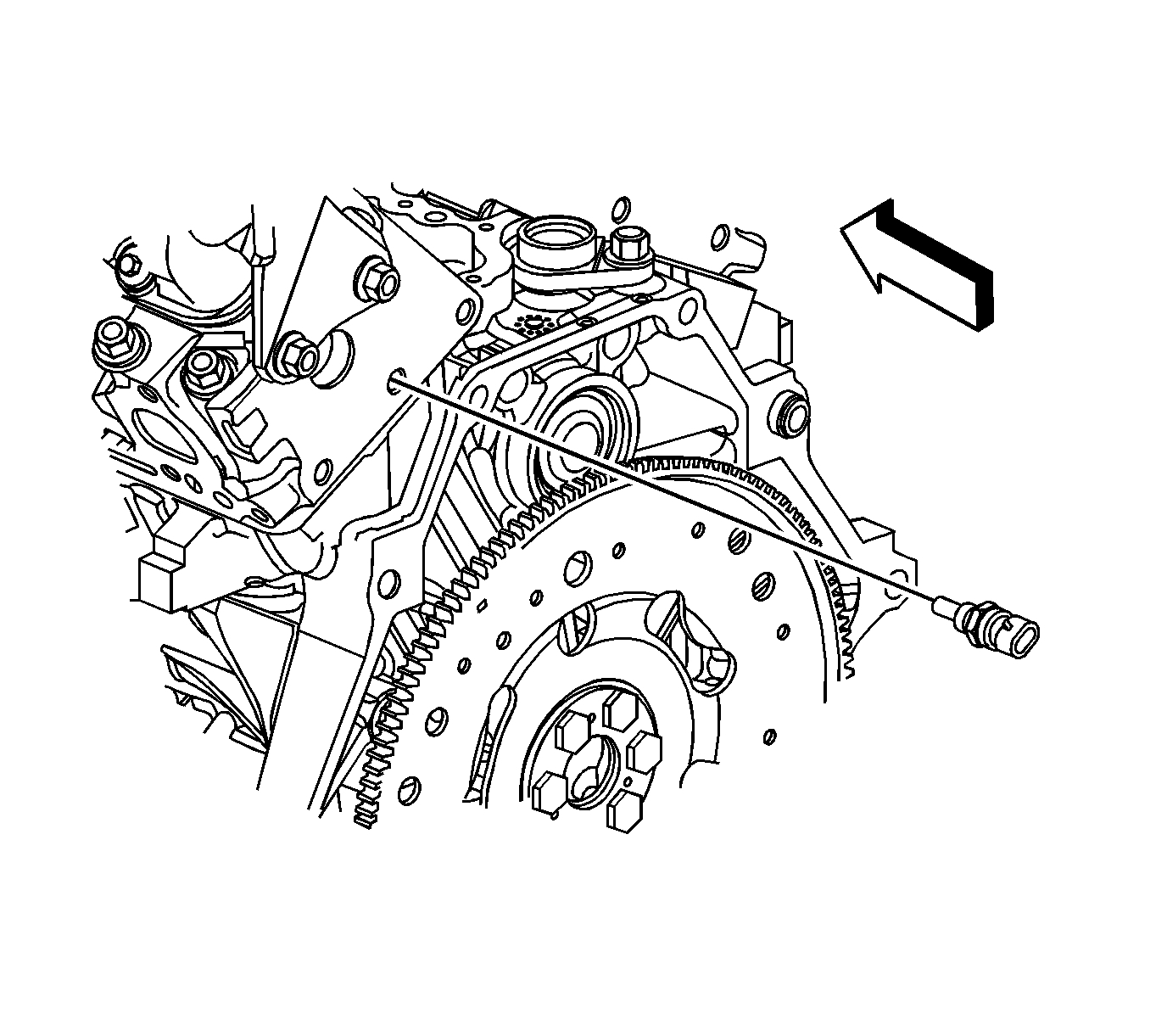

pic 4

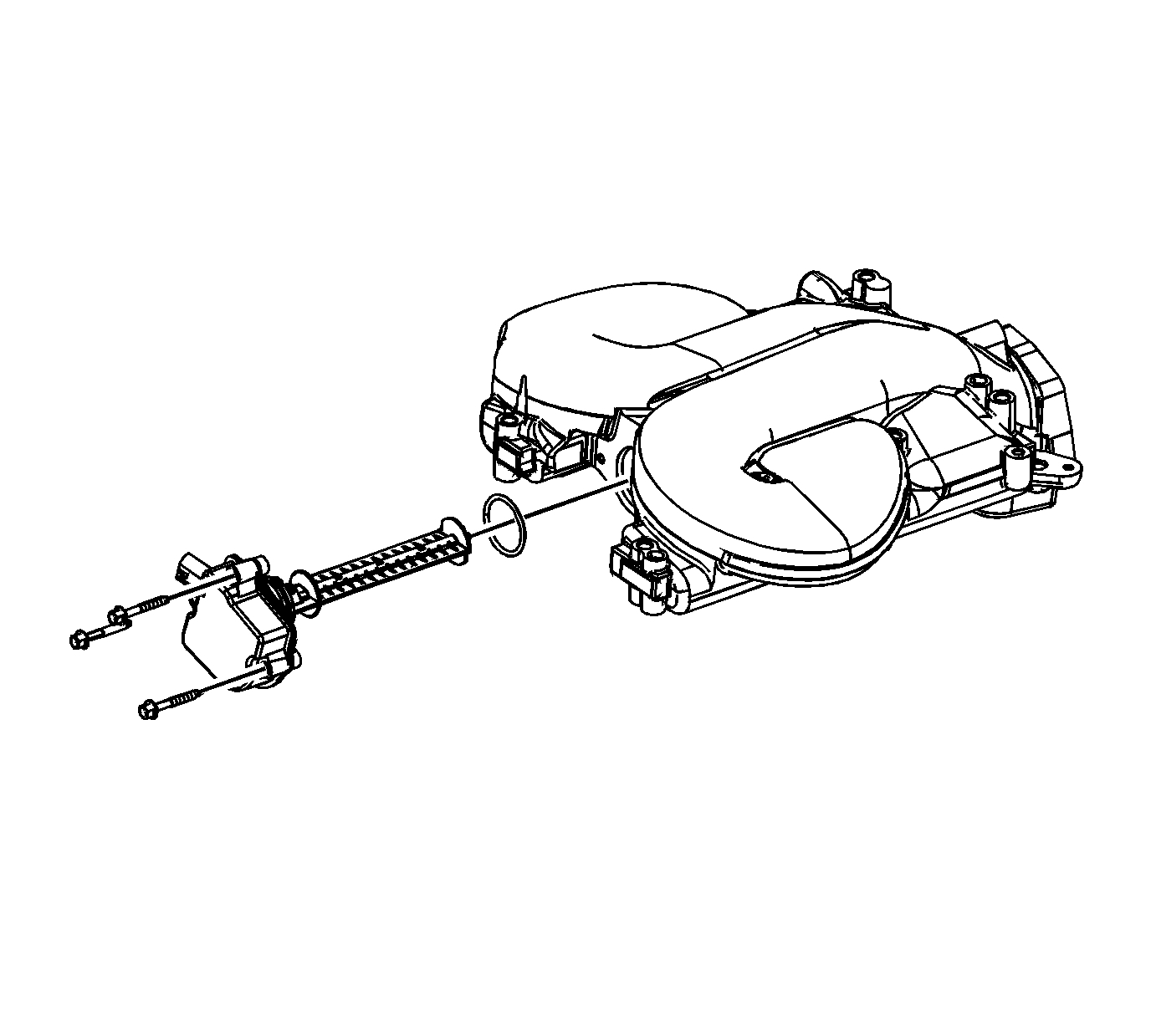
5. Remove the intake manifold tuning valve bolts.
6. Remove the intake manifold tuning valve.

INSTALLATION PROCEDURE


pic 5

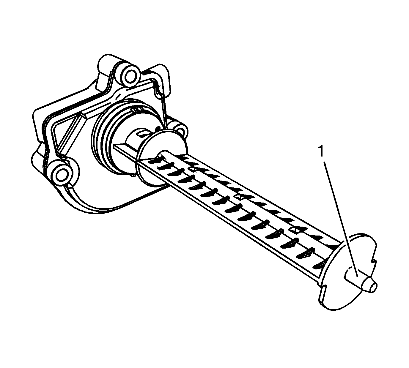
1. Apply lubricate GM P/N 1051344 (Canadian P/N 993037) to the nose of the valve blade (1).


pic 6

2. Install the intake manifold tuning valve.

NOTE: Refer to Fastener Notice.

3. Install the intake manifold tuning valve bolts.

Tighten the bolts to 10 N.m (89 lb in).

4. Install the power steering pump.


pic 7

5. Install the engine harness clip to the power steering reservoir bracket.
6. Connect the intake manifold tuning valve electrical connector (1).
7. Install the intake manifold cover.

_______________________________


I hope this helps. If you have a chance, let me know what you find. Also, let me know if you have other questions or need help. However, I feel everything is related.

Take care,
Joe
Nov 12, 2020 at 10:42 AM (Merged)
Avatar
JIMB2020
  • MEMBER
  • 106 POSTS
Okay, I will test and evaluate per instruction. So, you're saying the Radiator Fan isn't functioning after the temperature rises due to the P0660 and related codes? In other words, the IMT valve issue must be repaired before looking into the ECT, Thermostat or ECU/PCM (since the fan itself is functional)? Or are these totally separate repairs?
Nov 12, 2020 at 10:42 AM (Merged)
Avatar
JACOBANDNICKOLAS
  • CERTIFIED EXPERT
  • 110,175 POSTS
I would focus on the IMT first. We have codes specific to that. Once that is repaired, everything else may take care of itself.

Let me know what you find.

Take care,
Joe
Nov 12, 2020 at 10:42 AM (Merged)
Avatar
SAB1821
  • MEMBER
  • 1 POST
My engine light comes on for a few days then goes off. My water temperature guage does the same. My heater is working and the car seems to be driving okay. What is the problem?
Nov 12, 2020 at 10:42 AM (Merged)
Avatar
JACOBANDNICKOLAS
  • CERTIFIED EXPERT
  • 110,175 POSTS
What I need you to do is take the car to a nationally recognized parts store when the light is on. Have them scan the computer for trouble codes. Most places will do it for free. Let me know what codes you get.

Joe
Nov 12, 2020 at 10:42 AM (Merged)
Avatar
SMILCHER
  • MEMBER
  • 2 POSTS
2006 Pontiac G6 4 cyl

I have a 2006 Pontiac G6. My ac clutch will not engage periodically for a few days and then start working again in a few days. When this happens the temp gauge will not work and when the ac starts working again so will the temp gauge. What could be causing this. I have plenty coolant in the ac system and I have check all my fuses and relays.
Nov 12, 2020 at 10:42 AM (Merged)
Avatar
JACOBANDNICKOLAS
  • CERTIFIED EXPERT
  • 110,175 POSTS
Have you had the body control module checked?
Nov 12, 2020 at 10:43 AM (Merged)
Avatar
SMILCHER
  • MEMBER
  • 2 POSTS
Thanks for your reply. After looking through different forums I finally found someone that had the same problem. Apparently if the thermostat gets stuck the ac will stop working. I guess some kind of safety feature. I changed to thermostat and everything works great. Just in case you come across this in the future.
Nov 12, 2020 at 10:43 AM (Merged)
Avatar
JACOBANDNICKOLAS
  • CERTIFIED EXPERT
  • 110,175 POSTS
If the engine temp raises above a certain temp, that happens. Regardless, I'm glad you got it fixed. Let us know if you have questions in the future.
Nov 12, 2020 at 10:43 AM (Merged)