Code P0500, the speedometer stopped working after coil replacement?

1999 LEXUS RX 300
230,567 MILES • 3.1L • V6 • 2WD • AUTOMATIC
Avatar
MALLYBOY
  • MEMBER
  • 327 POSTS
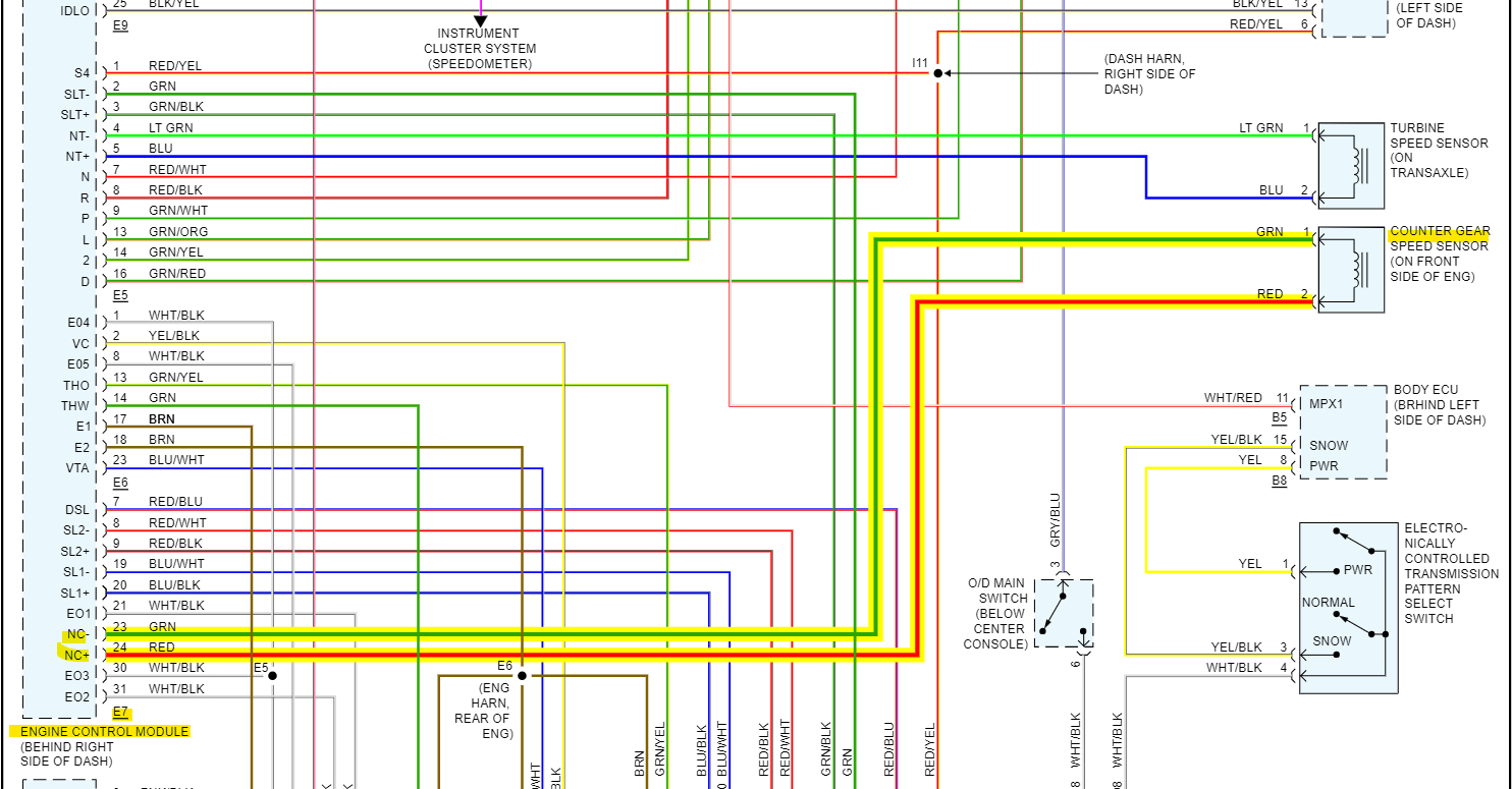
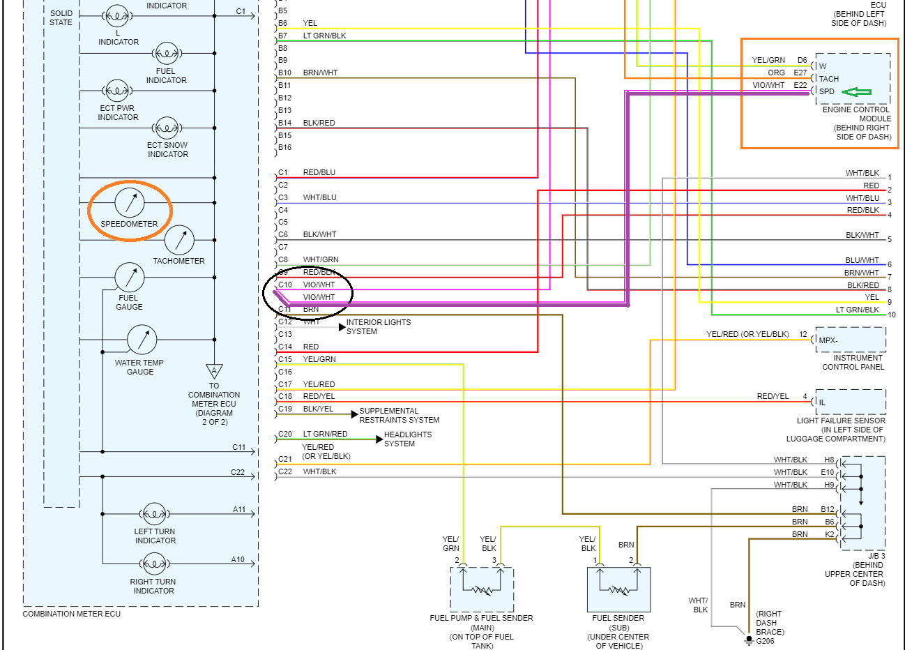
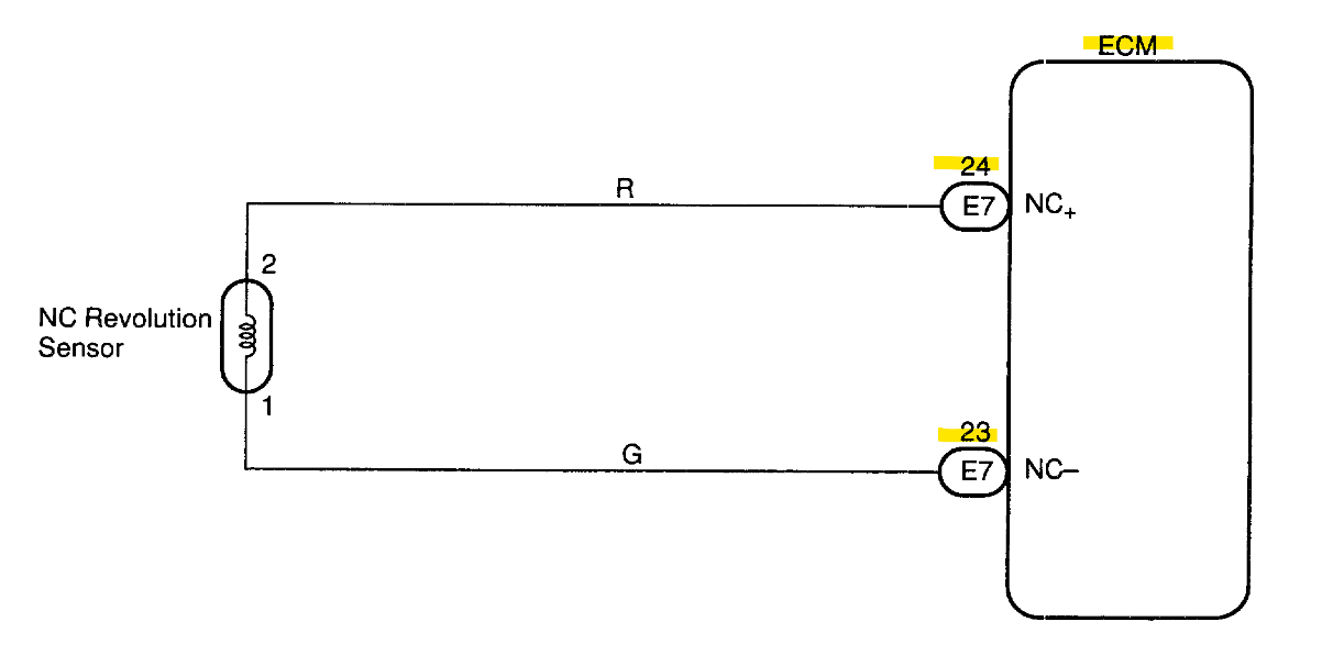
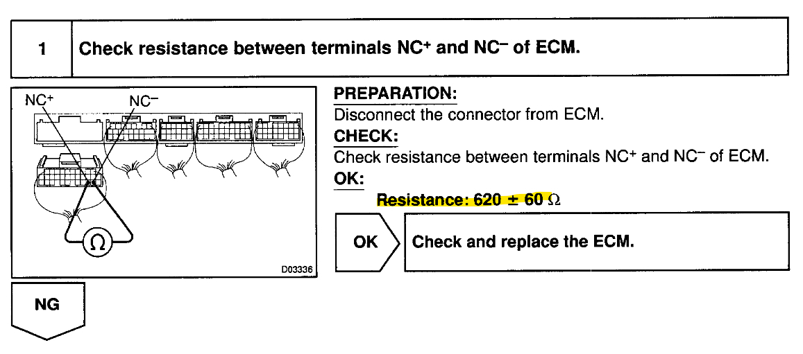
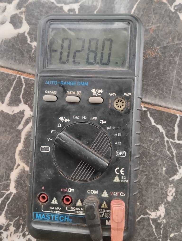
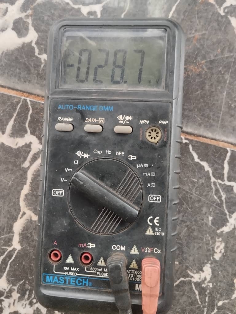
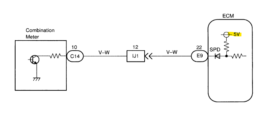
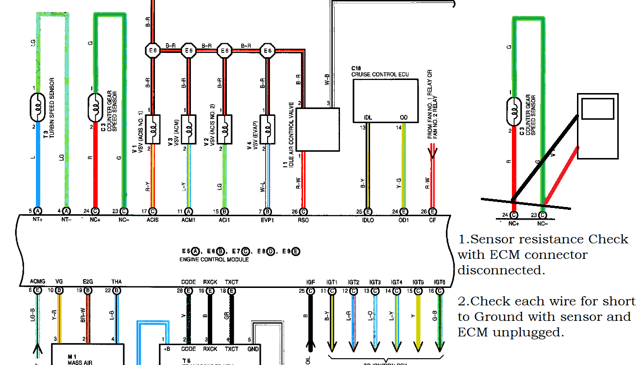
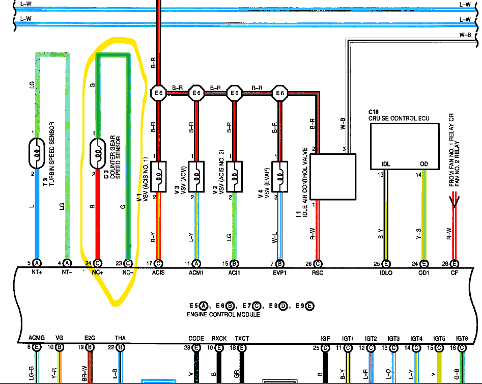
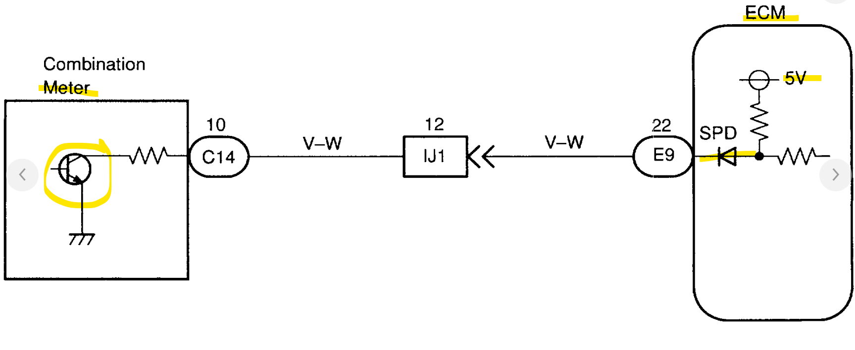
The speedometer stopped working after coil replacement. I have changed the ABS Module, it worked and stopped again. I used another speed clock and check, and it didn't work. I changed the ABS Actuator without connecting the brake pipes and it didn't work. I got another ECM and program it but it still didn't work. So, I began circuit by checking power supply to ABS module from ECU-B Fuse and there's power supply. I checked the Speedline wire violet/white; from ECM E9(22) to speed clock C3(10) and there was continuity, I measured the voltage with ignition on and it read 4.67volts. I also checked the Speedline wire (yellow wire) from ABS ECU B (16) to speed clock A (17) with engine on and gear shifter in D-position with one wheel spinning and it read 10volts. Finally, I measured voltage on the ABS sensor FR and FL, with the sensor disconnected it reads 0.5volts and when you plug in the sensor connector it drops from 0.5 to 45-50mv. At this point, I want to know how many volts the ABS ECU uses to control the sensor.
Jul 31, 2023 at 1:44 AM
Advertisement
Avatar
AL514
  • CERTIFIED EXPERT
  • 5,464 POSTS
Hello, this started happening after replacing an ignition coil? This vehicle looks to have coil over plug ignition coils, correct? Did only replace one coil, or a few coils? And what brand coil did you install and did you replace the spark plug also?
Jul 31, 2023 at 2:13 PM
Avatar
MALLYBOY
  • MEMBER
  • 327 POSTS
I replaced 5-coils to the cylinders that record coil malfunction which are: P1300-#1,P1310-#3,P1315-#4,P1320-#5 and P1325-#6. I also replaced the spark plugs.
Jul 31, 2023 at 2:41 PM
Advertisement
Avatar
AL514
  • CERTIFIED EXPERT
  • 5,464 POSTS
And I assume that none of those IGFI circuit codes came back. Since the speed sensor issue appeared after replacing the coils, I'd be concerned with either one of the coils having an issue with transient voltage spikes on the ground side getting into the counter gear speed sensor or output shaft speed sensor. The signal from those sensors is sent to the combination meter and then transmitted to the ECM. I don't think this has anything to do with the ABS wheel speed sensors, do you have a scope to check for any voltage spikes on the ground side of things? I have seen that happen many times, if any of the ignition coils are arcing outside the cylinder and going directly to ground it will affect the speed sensor signals. This might be the 2nd vehicle today with this issue, but being that you just replaced the coils, they would be the main suspect here. It's usually always the coils that end up with transient spikes in the grounds because they are the highest voltage components on the vehicle.
I'll try to find you a video on this, but if you have access to a scope and can check the grounds on this counter gear speed sensor and or the output shaft speed sensor, you might see some spikes hitting these ground circuits.
The counter gear speed sensor is supposed to be on the front side of the engine, but I think you would see it on the output shaft speed sensor as well. Those type of voltage spikes are pretty big, and I have seen them set output shaft speed sensor codes as well as stall vehicles right out.
I'll try to find a video that shows this, maybe it will help and you won't have to mess around with ABS circuits. These videos are super helpful
Ok this is the video I wanted to show you, just to get an idea of what might be happening. It's about 45 minutes, but you can jump forward, and you'll know what is going on with the vehicle in the video about 7 minutes in.

https://www.youtube.com/watch?v=Yjt6r1fNN0w
Jul 31, 2023 at 3:14 PM
Avatar
MALLYBOY
  • MEMBER
  • 327 POSTS
And I assume that none of those IGFI circuit codes came back. No, it didn't come back.

This reminds me that when I start the vehicle and engage gear and allow the tire to spine without depressing gas pedal, check lights up and if you scan, you see P0500. Then I unplug the Counter gear speed sensor (NC) connector and spin the tire again the check engine light didn't appear again and the fault code didn't come up but the Speed clock was not rising. Then I used scanner to read live data of the input turbine and output shaft speed sensor, at 750rpm, the input will be at 0rpm while the output will be 60-100rpm, then when you engage gear and allow the tire to spin, both sensor will begin to count, and 2000rpm, both sensor will be at 6000rpm but I will record the live data again and send to you for proper analysis.
Aug 1, 2023 at 3:01 AM
Avatar
AL514
  • CERTIFIED EXPERT
  • 5,464 POSTS
Thats interesting, technically the code P1730 should set with the counter gear speed sensor unplugged. You didn't notice any trans fluid leaks around the counter gear sensor, did you? There is a TSB on fluid leaks from the counter gear sensor bolt hole. But this Vehicle Speed Sensor Monitor for that code (P0500) states that the vehicle speed signal can be sent in different ways depending on the vehicle model. And I don't know if when the code sets the ECM may disregard that signal due to the fault.
In your scan data do you see a Vehicle speed data PID anywhere? To see if the ECM is receiving a signal from any sensor at all.
The code criteria state the P0500 is set when the ECM is not detecting any vehicle speed signal, and some trouble areas are -Open or Short in Vehicle Speed sensor circuit (Which would cause no signal at all the Cluster or ECM. Thats the path the signal looks to take, From the speed sensor to the Cluster and then to the ECM. So, it could be a bad sensor, open/short circuit, bad Cluster, or ECM. I don't think ECM, I think the signal is just not making it there.
If your scan tool can access the Cluster and check for any live data that would help. But there is also a Flow Chart Ill post here in a minute for you, so you can check the circuits between the ECM, Cluster, but it also states that "The vehicle speed sensor is operating normally if the Speedometer is displaying correctly" which it isn't. And since your Input (Turbine) shaft speed sensor is sending a signal, Id focus on this Counter Gear Speed sensor,
Service info has you replace both of those sensors, but The Input sensor is working.
I'll see if I can find any resistance spec for that counter gear sensor and the wiring diagram for is, but check to see if it has an open circuit inside, just unplug it and do a Ohms check across its 2 pins, If it's an open circuit inside, then you found the issue.
Aug 1, 2023 at 10:51 AM
Avatar
AL514
  • CERTIFIED EXPERT
  • 5,464 POSTS
Okay, there is a resistance check at the sensor, 620 Ohms +/- 60. And then if that's okay, you can check for that same resistance spec from the ECM connector which would show if you had a complete circuit. It looks like the Counter Gear Speed sensor does signal directly to the ECM and then out to the Cluster, Service info is a bit shady here. But this should help you out. There might even be a bias voltage at the Counter Gear sensor connector coming from the ECM. Some manufacturers do this to verify the circuit, one diagram showed a 5v Reference from the ECM to the Cluster, but it's not clear for that sensor, but if you read any bias voltage with the sensor unplugged, you can check for that same voltage level coming out of the ECM on the sensors circuit.
You can also check for any shorts to ground by disconnecting the sensor, and ECM connector, then check for any stray voltage or ground on those 2 wires, with them isolated like that there shouldn't be anything at all on them.
Aug 1, 2023 at 11:11 AM
Avatar
MALLYBOY
  • MEMBER
  • 327 POSTS
Okay, thank you so far.

Thats interesting, technically the code P1730 should set with the counter gear speed sensor unplugged. No, it didn't set a fault code

I have check Resistance and Voltage test at:
1. The violet/white wire running ECM E22(9) to instrument cluster C (10) there was resistance and Voltage at 4.67v and when I engage gear and spin the Tire, the Voltage remain the same 467, should there be a change in voltage as the tire begin to spin?
2. On the NT(Input) and NC (output) speed sensor, I have checked resistance and Voltage with ignition on, using DVOM set DC range with red lead probe to terminal 2 red wire and black lead to terminal 1 of input and output, it was reading 25 to 30mv. I want to ask; how many volts does ECM uses to operate the sensors? I attach below live data and waveform of those sensors.
Aug 1, 2023 at 10:01 PM
Avatar
AL514
  • CERTIFIED EXPERT
  • 5,464 POSTS
Hello, I don't see any waveforms or data in your post. Our system here has a spam filter, so don't include any keyboard symbols, only pictures. As for the testing, what was the resistance of the Counter Gear speed sensor unplugged? You can't have it plugged in when checking the resistance of the sensor itself because it will measure the entire circuit's resistance. It should be around 620 Ohms. The 5volt is a reference voltage from the ECM to the Cluster. We need to know if the Counter Gear sensor is ok first. So, check the resistance of just the sensor unplugged, not with your meter on a voltage setting. The Ohms symbol is the 2nd pic below. The 5volt Reference is good that it is there. That means the circuit from the ECM to the Cluster, that wire is ok.
These speed sensors are a VR type 2 wire sensor, so they produce a very low voltage signal when the vehicle is moving. Other sensors, such as a Hall Effect sensor is a 3 wire more technical type of sensor. It works on a 12volt or 5volt feed and is a digital type on/off signal because there is a transistor built into the sensor.
After you check the resistance of the sensor alone, with the meter set on the Ohms setting and I'm not sure what type of multimeter you have, but here I circled the 2000 Ohm setting because the sensor should be up to 620 Ohms, if you have an auto-range meter then just set it on the Ohms(Resistance) setting and it should auto-range the reading.

After you have the resistance of the sensor, you can measure the resistance from the ECM connector pin 24 (E7-NC+) to sensor harness pin 2. The ECM pin 23 (E7-NC-) to sensor harness pin 1. Key Off, engine Off, both unplugged should show less than 5 ohms on each wire. (Diagram 4)
Aug 2, 2023 at 8:00 AM
Avatar
MALLYBOY
  • MEMBER
  • 327 POSTS
I have done the test, remove the sensor out from transmission and I set the DVMM to Ohm scale and probe the pin 1 with black lead and pin 2 with red lead, it was giving 0.625 Kilo-ohms and I attach below.
Aug 2, 2023 at 10:33 AM
Avatar
MALLYBOY
  • MEMBER
  • 327 POSTS
Again, I set to voltage dc scale and measure; it was giving me -028.0 millivolt. Then I put magnet on the tip and removed it quickly, it read -028.7 mv. Why the negative signal and is the value correct?
I attached picture for you to see.
Aug 2, 2023 at 10:45 AM
Avatar
AL514
  • CERTIFIED EXPERT
  • 5,464 POSTS
Okay, then the sensors resistance is correct. Was there any type of dirt or metal sticking to the end of the sensor? This is the 5volts you were reading from the PCM to Cluster.
With the PCM disconnected, check for that same resistance reading across the two ECM connector pins and then disconnect the sensor as well and check each wire for a short to ground with the meter on resistance setting.
Aug 2, 2023 at 10:56 AM
Avatar
AL514
  • CERTIFIED EXPERT
  • 5,464 POSTS
That's because it's a VR sensor, it sends a sinewave type signal, just like a 2-wire crankshaft pos sensor. Refresh this page and check my last post, there is an OEM diagram to check those 2 wires for any shorts to ground and to make sure there is a complete circuit from the PCM connector to the sensor and then back to the PCM connector.
Aug 2, 2023 at 10:58 AM
Avatar
MALLYBOY
  • MEMBER
  • 327 POSTS
Was there any type of dirt or metal sticking to the end of the sensor? Yes, there was. I remember that was what I did before when the clock was not reading, I remove the sensor and cleaned it with tissue paper, then put it back and I spin the tire it started working before I proceed with the coil replacement after which it stopped working before the coil replaced.
1. Sensor Resistance check with ECM disconnected, I have done that by probing the black lead to pin1 and red lead to pin2 and there was no resistance, I also probe from ECM connector C23 and C24 and there was no resistance. But I didn't check short ground I.e. probing the C23 on ECM connector and body ground; and C24 ECM connector to body ground?
Aug 2, 2023 at 2:21 PM
Avatar
MALLYBOY
  • MEMBER
  • 327 POSTS
There was something I noticed on the speed clock when I checked resistance. When I probe E9(22) ECM connector to C14(10), there was resistance, on that same E9(22), I probe C14(3)white/blue wire running power from engine compartment fuse box to instrument fuse box to combination meter through ECU B FUSE 7.5A., there was resistance, So also to C14(14) thorough Dome fuse, there was resistance, is this thing correct? Are there supposed to be resistance on them, since they are different circuit?
Aug 2, 2023 at 2:37 PM
Avatar
AL514
  • CERTIFIED EXPERT
  • 5,464 POSTS
You can take an accurate resistance reading on any circuit while it is plugged in, you will end up reading the resistance of the entire circuit. Many components in an automotive harness all basically share the vehicles ground section and many components are fed power by one fuse, so to properly check the resistance of a circuit from one end to the other they need to isolated from anything else, Another thing is that every single connection, even where a fuse makes contact in a fuse box while have a certain amount of resistance to them. Thats why I was suggesting to just test the unplugged ECM connector pins 23 and 24 to see if you get around the same reading of the sensor's resistance. Concentrate on the one circuit that is setting the code for now. We need to know if there is a complete circuit to the sensor and back, and then if either leg of that circuit is shorted to ground anywhere.

I see the circuits you are checking,
but just check for the 620 ohms on those 2 ECM connector pins to the counter gear sensor, then unplug the sensor and check for continuity to ground on each wire separately still with the ECM unplugged. If either wire has a short to ground there wont be any signal making it to the ECM. We have to be sure of this circuit first, Service info varies here on the way this is routed. One section states the CounterGear sensor runs to the Cluster then to the ECM, but this OEM diagram shows it differently. So, check that first.
Aug 3, 2023 at 7:20 AM
Avatar
MALLYBOY
  • MEMBER
  • 327 POSTS
Hi!
I have done the test of Resistance by setting the DMM on ohm scale and read the counter gear sensor on ECM connector while unplugged. I probe C23 and C24 of counter gear sensor while plugged, it read 0.609+/-11. When I unplug the sensor and read again, it was O.L, I check resistance to ground by probing C23 and body ground, and also to C24 and body ground, and also to each wire of counter gear sensor connector and body ground, there was no continuity. I check resistance on C23 to pin 1 of counter connector, it reads 000.0ohms and also to C24 to pin2, the same 000.0ohms.
I also replaced the input and counter gear speed sensor but the check light still appears, but the speedometer didn't rise.
I think I have to inspect the abs now as I have solved P0500 before on 2001 sienna by replacing abs-pump and ECU. The speed clock rise and P0500 stop coming back.
Aug 4, 2023 at 2:30 PM
Avatar
AL514
  • CERTIFIED EXPERT
  • 5,464 POSTS
Well, these are the OEM trouble shooting flow chart for that code. The only thing you didn't check was for voltage on either wire. There's no section on ABS for it, and I've gone through all the service info there is. If this first section of the flow chart is correct, There should be a 5-volt 4 pulse signal from the Cluster going to the ECM, since there is a 5v-Ref coming from the ECM to the Cluster which you had a voltage for, and there is a transistor in the Combo Meter, which makes this a pull down signal circuit, so the Meter pulls the circuit down to ground through its transistor (diagrams 5,6) producing the square wave 4 pulse signal. Service info doesn'tt state anywhere that it uses the ABS wheel speed sensors for the Speedometer. Unless it compares multiple inputs.
Aug 4, 2023 at 4:05 PM
Avatar
MALLYBOY
  • MEMBER
  • 327 POSTS
The diagram6 well explained this situation. Because from the monitor description, it stated that there are 3 detection methods and the signals travel to ECM differently depending on the model.
Method A: a vehicle speed sensor built into each wheel detects vehicle speed signals and these signals are sent to ECM through skid control ECU (ABS module) and combo meter.
Therefore, where the vehicle does not have the 3pin speed sensor built on transmission, Method A becomes the means the vehicle uses to transmit vehicle speed signals through the ABS speed sensors built into each wheel. So, is there a way i can read ohms resistance on the ABS wheel speed sensors to detect the malfunction sensors and how to read them?
Aug 7, 2023 at 3:15 AM
Avatar
AL514
  • CERTIFIED EXPERT
  • 5,464 POSTS
You can check for codes in the ABS unit by using the DLC1 connector method, this is not the Data Link Connector under the dash, it's in the engine compartment, you just jump out two pins on the connector, turn the key On and count how many times the ABS light blinks.
You said you replaced the Input Turbine shaft speed sensor as well?
I don't see any spec on resistance for the wheel speed sensors, Ill post it if I can find it, but you can compare each sensor to the others, they couldn't all fail at once. To read the wheel speed sensors you would need to scan tool that could access the ABS module and look at its live data for each sensor.
Aug 7, 2023 at 11:00 AM
Avatar
MALLYBOY
  • MEMBER
  • 327 POSTS
I have jumper the E1 and Ts on DLC1, then the ABS warning light blinks slowly for 3 times and begins to blink faster for more than 2 minutes without stopping, which code is this?
Aug 8, 2023 at 10:58 AM
Avatar
AL514
  • CERTIFIED EXPERT
  • 5,464 POSTS
Hello sorry for the delay, I lost power and internet for a few days due to a huge storm that hit here.
Are you able to count the number of blinks after the 3? The flashes should be a 1/4 of a second apart. Is it possible there is 1 flash and then 3 and then the steady flash after that. A code 31 would be Right Front Wheel speed sensor, so passenger side front. The listing starts with code 11 so there is no code 3. Does it repeat the flashes after two minutes? I'll post the code lists for you.
This is just the ABS light flashing, not any Traction control light as well, correct?
Aug 9, 2023 at 11:18 AM
Avatar
MALLYBOY
  • MEMBER
  • 327 POSTS
Hello, thank you so far!
I have come to tell you that I have solved the P0500 by replacing the right front abs wheel speed sensor and the problem solved. I have yet to replace the left front ABS wheel speed sensor to complete the speed sensor circuit.
How do I reset ABS ECU memory?
Aug 9, 2023 at 2:31 PM
Avatar
AL514
  • CERTIFIED EXPERT
  • 5,464 POSTS
Okay cool, so it was a code 31, To clear the ABS codes without a scan tool, Ignition switch Off,
jumper to Tc to E1 with the Shorting pin removed, Key On, press the Brake pedal 8 times in 5 seconds. Recheck for any codes, Constant flashing means no codes. It doesn't say, but Id assume key Off, then pull the jumpers out and reinstall the Short Pin where it was, and that should be all.
Is your Speedometer working correctly now?
Aug 9, 2023 at 2:53 PM
Avatar
MALLYBOY
  • MEMBER
  • 327 POSTS
Your Speedometer is working correctly now? Yap For sure.
I have done that but it didn't work, I jumper E1 and Ts: it blink 3times and begin to blink faster, then I jumper E1 and TC, that was when I began to get Code 31 and 32 only even after replacing one side of abs sensor
Aug 9, 2023 at 7:06 PM
Avatar
AL514
  • CERTIFIED EXPERT
  • 5,464 POSTS
Did you pull out the Short Pin jumper the first time you pulled the ABS code? I'm wondering if service info is incorrect with that. I don't remember the code retrieving section had that included. E1 to Ts is for pulling codes, the E1 to Tc is for erasing codes.
Aug 9, 2023 at 7:35 PM
Avatar
MALLYBOY
  • MEMBER
  • 327 POSTS
Did you pull out the Short Pin jumper the first time you pulled the ABS code? Yes I did
Aug 9, 2023 at 7:37 PM
Avatar
AL514
  • CERTIFIED EXPERT
  • 5,464 POSTS
It wasn't in the Speed sensor circuit check, look back at the first code retrieving info on the first page. There was no Short Pin jumper taken out. This is the last code instructions, this was what gave the 3 and multiple flashes after.
Aug 9, 2023 at 7:49 PM
Avatar
AL514
  • CERTIFIED EXPERT
  • 5,464 POSTS
Just try clearing the codes without reading them again.
Aug 9, 2023 at 7:56 PM
Avatar
MALLYBOY
  • MEMBER
  • 327 POSTS
On my own vehicle, the short pin was not even there at all.
Aug 9, 2023 at 7:57 PM
Avatar
MALLYBOY
  • MEMBER
  • 327 POSTS

Just try clearing the codes without reading them again.
Which terminal is the correct one for clearing codes E1 and TS or E1 and TC ?
Aug 9, 2023 at 8:00 PM
Avatar
AL514
  • CERTIFIED EXPERT
  • 5,464 POSTS
Tc and E1 to clear the codes, and the Brake pedal 8 times in 5 seconds.
Aug 9, 2023 at 8:57 PM
Avatar
MALLYBOY
  • MEMBER
  • 327 POSTS
Yep, thank you so far!

I have done that by jumper E1 and TC and immediately the ABS light began to blink, I depressed the brake pedal and it off, when I released the pedal, it came back and only return Code32 while code 31 is gone. Now if you jack up the right front tire and engage gear and spin the tire, the combo meter will work, but if you jack the left front tire and engage gear and spin the tire, the combo meter will not work. I replaced another used ABS sensor and first wanted to clear it, it wipe and return back. So, I will look for another tone ring and shaft head to retest it.
Aug 10, 2023 at 12:26 PM
Avatar
AL514
  • CERTIFIED EXPERT
  • 5,464 POSTS
That's unfortunate I thought we had it figured out. Can you pull the sensor out and see into the trigger/tone wheel and see if there's any dirt or corrosion in there, rust can cause this as well. With you working on things and moving them around, I wouldn'tt be surprised if there was rust stuck to the end of the sensor or in the tone wheel. The tone wheel is an exterior one on this right? It's not inside the wheel bearing.
Aug 10, 2023 at 12:35 PM
Avatar
MALLYBOY
  • MEMBER
  • 327 POSTS
The tone wheel is an exterior one on this right? Yes
Aug 10, 2023 at 2:10 PM
Avatar
MALLYBOY
  • MEMBER
  • 327 POSTS
I replaced left front abs wheel speed sensor and I reset the ABS module, then engage gear and spin the tire, the combometer started working. So that's the end.
Aug 11, 2023 at 3:19 PM
Avatar
AL514
  • CERTIFIED EXPERT
  • 5,464 POSTS
Strange, maybe it was the left front that was bad to begin with, and the module was comparing the two. But glad it's fixed.
Aug 11, 2023 at 3:34 PM