Hi,
Replacing rear brake pads and rotors really isn't that difficult. When you do it yourself, make sure to get lifetime replacement parts so you never have to pay again.
You can expect rear brakes to last approximately 30,000, but that will vary based on terrain and driving habits.
First, here is a link that shows in general how it's done. You can use this as a guide.
https://www.2carpros.com/articles/how-to-replace-rear-brake-pads-and-rotors
Here are the directions specific to your vehicle. The attached pics correlate with the directions.
____________________________________________
2007 Saturn ION L4-2.4L
Rear Disc Brake Pads Replacement
Vehicle Brakes and Traction Control Disc Brake System Brake Pad Service and Repair Removal and Replacement Rear Disc Brake Pads Replacement
REAR DISC BRAKE PADS REPLACEMENT
Rear Disc Brake Pads Replacement
Caution: Refer to Brake Dust Caution.
Caution: Refer to Brake Fluid Irritant Caution.
Removal Procedure
1. Inspect the fluid level in the brake master cylinder auxiliary reservoir.
2. If the brake fluid level is midway between the maximum-full point and the minimum allowable level, no brake fluid needs to be removed from the reservoir before proceeding.
3. If the brake fluid level is higher than midway between the maximum-full point and the minimum allowable level, remove brake fluid to the midway point before proceeding.
4. Raise and support the vehicle.
5. Remove the tire and wheel assembly.
6. Install and firmly hand tighten 2 wheel nuts to opposite wheel studs in order to retain the rotor to the hub.
pic 1
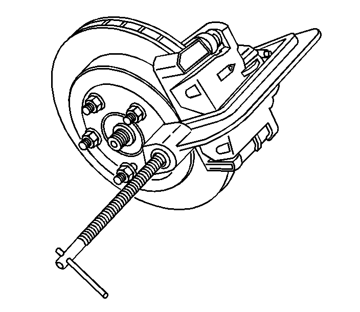
7. Install a large C-clamp, over the body of the brake caliper with the C-clamp ends against the rear of the caliper body and against the outer brake pad.
Notice: When using a large C-clamp to compress a caliper piston into a caliper bore of a caliper equipped with an integral park brake mechanism, do not exceed more than 1 mm (0.039 in) of piston travel. Exceeding this amount of piston travel will cause damage to the internal adjusting mechanism and/or the integral park brake mechanism.
8. Tighten the C-clamp just enough to compress the caliper piston 1 mm (0.039 in) of travel only.
9. Remove the C-clamp from the caliper.
pic 2
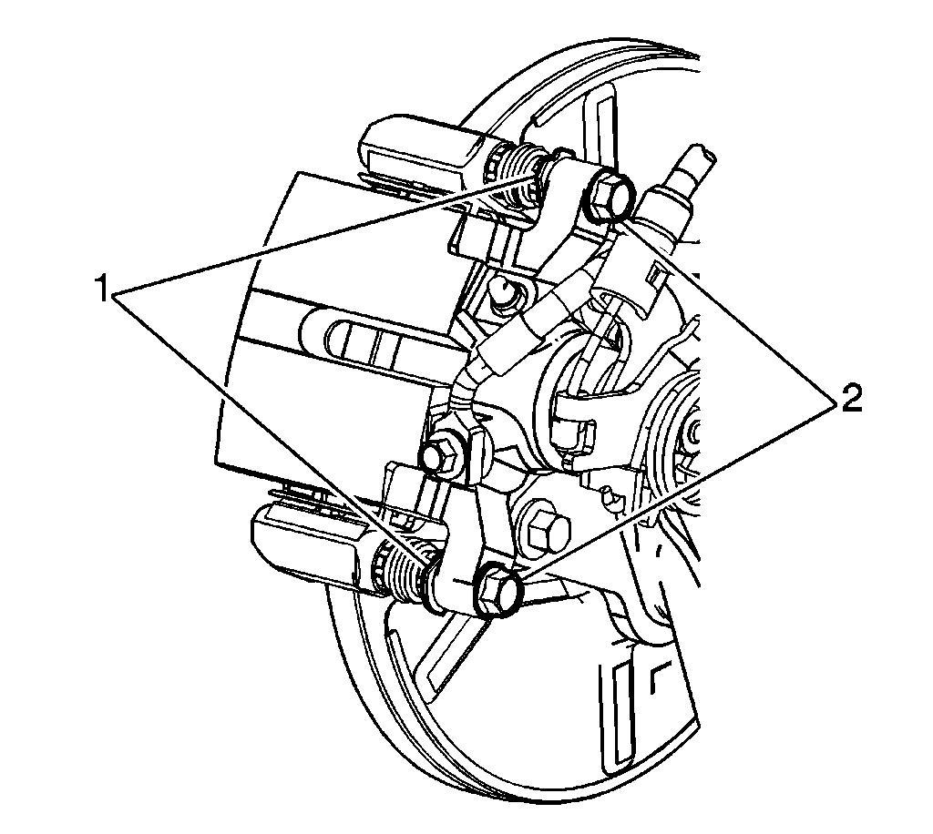
10. While using a wrench on the flats of the caliper guide pins (1), remove the brake caliper guide pin bolts (2).
Notice: Support the brake caliper with heavy mechanic's wire, or equivalent, whenever it is separated from its mount and the hydraulic flexible brake hose is still connected. Failure to support the caliper in this manner will cause the flexible brake hose to bear the weight of the caliper, which may cause damage to the brake hose and in turn may cause a brake fluid leak.
11. Without disconnecting the hydraulic brake flexible hose, remove the caliper from the mounting bracket and secure the caliper with heavy mechanics wire, or equivalent.
pic 3
12. Remove the brake pads from the caliper mounting bracket.
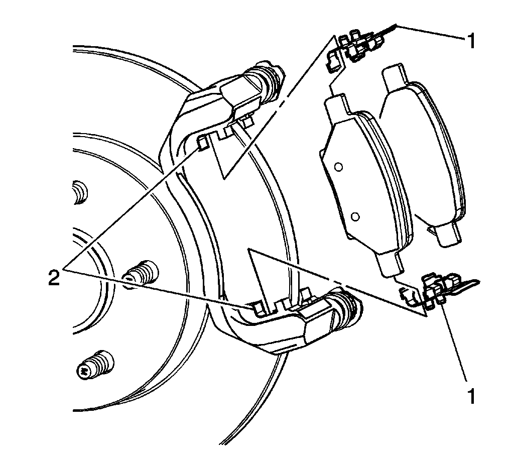
13. Remove the brake pad retainers (1) from the caliper bracket.
14. Thoroughly clean the brake pad hardware mating surfaces of the caliper bracket (2), of any debris and corrosion.
15. Inspect the brake caliper guide pins for freedom of movement, and inspect the condition of the guide pin boots. Move the guide pins inboard and outboard within the bracket bores, without disengaging the slides from the boots, and observe for the following:
^ Restricted caliper guide pin movement
^ Looseness in the brake caliper mounting bracket
^ Seized or binding caliper guide pins
^ Split or torn boots
16. If any of the conditions listed are found, the brake caliper guide pins and/or boots require replacement.
pic 4
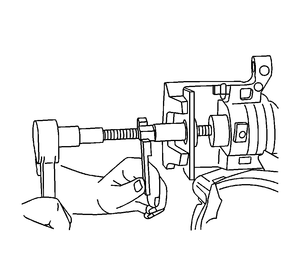
17. Using a spanner wrench type caliper piston installer, fully retract the piston into the caliper bore.
Installation Procedure
pic 5
1. Apply a very thin coating of high temperature silicone brake lubricant to the pad hardware mating surfaces of the caliper bracket (2) only.
2. Install the brake pad retainers (1) to the brake caliper bracket.
Important: The wear sensor equipped disc brake pad must be mounted inboard of the rotor with the leading edge of the sensor facing the brake rotor during forward wheel rotation, or at the bottom of the pad when installed in vehicle position.
3. Install the brake pads to the caliper bracket.
4. Remove the support, and install the caliper into position over the disc brake pads and to the caliper mounting bracket.
pic 6
Notice: Refer to Fastener Notice.
5. While using a wrench on the flats of the caliper guide pins (1), install the brake caliper guide pin bolts (2).
Tighten the bolts to 34 N.m (25 lb ft).
6. Remove the wheel nuts retaining the brake rotor to the hub.
7. Install the tire and wheel assembly.
8. Lower the vehicle.
9. With the engine OFF, gradually apply the brake pedal approximately 2/3 of its travel distance.
10. Slowly release the brake pedal.
11. Wait 15 seconds, then gradually apply the brake pedal approximately 2/3 of its travel distance again until a firm brake pedal apply is obtained. This will properly seat the brake caliper pistons and brake pads.
12. Fill the master cylinder auxiliary reservoir to the proper level.
13. Burnish the pads and rotors.
_________________________________________
Rotor Replacement
2007 Saturn ION L4-2.4L
Rear Brake Rotor Replacement
Vehicle Brakes and Traction Control Disc Brake System Brake Rotor/Disc Service and Repair Removal and Replacement Rear Brake Rotor Replacement
REAR BRAKE ROTOR REPLACEMENT
Rear Brake Rotor Replacement
Tools Required
* J 41013 Rotor Resurfacing Kit
* J 42450-A Wheel Hub Resurfacing Kit
Caution: Refer to Brake Dust Caution.
Removal Procedure
1. Raise and support the vehicle.
2. Remove the tire and wheel assembly.
pic 7
3. Install a large C-clamp, over the body of the brake caliper with the C-clamp ends against the rear of the caliper body and against the outer brake pad.
Notice: When using a large C-clamp to compress a caliper piston into a caliper bore of a caliper equipped with an integral park brake mechanism, do not exceed more than 1 mm (0.039 in) of piston travel. Exceeding this amount of piston travel will cause damage to the internal adjusting mechanism and/or the integral park brake mechanism.
4. Tighten the C-clamp just enough to compress the caliper piston 1 mm (0.039 in) of travel only.
5. Remove the C-clamp from the caliper.
pic 8
Notice: Support the brake caliper with heavy mechanic's wire, or equivalent, whenever it is separated from its mount and the hydraulic flexible brake hose is still connected. Failure to support the caliper in this manner will cause the flexible brake hose to bear the weight of the caliper, which may cause damage to the brake hose and in turn may cause a brake fluid leak.
Important: Do not disconnect the hydraulic brake flexible hose from the caliper.
6. Remove the brake caliper and the caliper mounting bracket as an assembly from the steering knuckle and support the assembly with heavy mechanic's wire, or equivalent. Ensure that there is no tension on the hydraulic brake flexible hose.
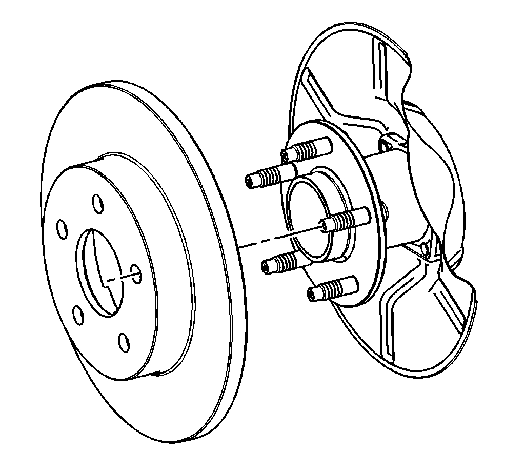
7. Matchmark the position of the brake rotor to the wheel studs.
8. Remove the brake rotor.
Installation Procedure
pic 9
Important: Whenever the brake rotor has been separated from the hub/axle flange, any rust or contaminants should be cleaned from the hub/axle flange and the brake rotor mating surfaces. Failure to do this may result in excessive assembled lateral runout (LRO) of the brake rotor, which could lead to brake pulsation.
1. Using the J42450-A, thoroughly clean any rust or corrosion from the mating surface of the hub/axle flange.
2. Using the J41013, thoroughly clean any rust or corrosion from the mating surface and mounting surface of the brake rotor.
3. Inspect the mating surfaces of the hub/axle flange and the rotor to ensure that there are no foreign particles or debris remaining.
4. Install the brake rotor to the hub/axle flange. Use the matchmark made prior to removal for proper orientation to the flange.
5. If the brake rotor was removed and installed as part of a brake system repair, measure the assembled lateral runout (LRO) of the brake rotor to ensure optimum performance of the disc brakes.
6. If the brake rotor assembled LRO measurement exceeds the specification, bring the LRO to within specifications.
7. Remove the support, and install the brake caliper and the brake caliper bracket as an assembly to the steering knuckle.
8. Install the tire and wheel assembly.
9. Lower the vehicle.
10. If the brake rotor was refinished or replaced, or if new brake pads were installed, burnish the pads and rotors.
______________________
I hope this helps. Let me know if you have other questions,
Take care and God Bless,
Joe
Images (Click to enlarge)
Mar 2, 2021 at 1:44 PM