Rear blower motor not working

2005 GMC YUKON
223,000 MILES • 6.0L • V8 • 4WD • AUTOMATIC
Avatar
ELMERMAXX
  • MEMBER
  • 20 POSTS
The blower is fine, I took it out and tested at the battery. I replaced the blower motor module, and it still does not work. I'm stumped.
Jun 4, 2022 at 4:39 PM
Advertisement
Avatar
KASEKENNY
  • CERTIFIED EXPERT
  • 18,907 POSTS
Just to be sure you replaced the aux blower motor control module and not the one in the front.

If you did, then we need to check two more things.

First, we need to check the power at the blower motor and confirm you are getting 12-volts when it is on high.

https://www.2carpros.com/articles/how-to-check-wiring

Then we need to check the grounds by using the 12-volt source and then both grounds and your meter should read 12-volts.

If it does, then we need to move to the control processor. We need to check and find out if there are 12-volts on the B+ circuit and then the speed control should change as you increase the speed.

Lastly, we need to check this ground the same as the other.

Please run through this and let us know what you find and then we can go from there to find out the next steps.
Jun 5, 2022 at 5:21 PM
Avatar
ELMERMAXX
  • MEMBER
  • 20 POSTS
Power at purple motor wire 12v, grounds check out, signal wire seems to change with speed.
The black ground next to B+ red wire is fine. The B+ wire has 12 v, the sig wire seems to change when fan speed is changed, the orange wire ground for the motor doesn't seem to work, the purple power wire to fan has 12v. If i jump a wire from the pillar ground the motor runs.
Does this help at all, or does it mean I have a bad module?
Jun 13, 2022 at 12:12 PM
Advertisement
Avatar
KASEKENNY
  • CERTIFIED EXPERT
  • 18,907 POSTS
Just to be sure, you are jumping a wire from the motor to ground and the motor runs.

Can you confirm what terminal you are jumping this wire from on the motor to ground?

I am attaching the blower motor connector below. Thanks
Jun 13, 2022 at 2:58 PM
Avatar
ELMERMAXX
  • MEMBER
  • 20 POSTS
Yes, I used the black wire B on the pic.
Jun 14, 2022 at 10:01 AM
Avatar
ELMERMAXX
  • MEMBER
  • 20 POSTS
Sorry I had issues connecting to the site. Yes, I jumpered the B wire in the connector, actually it's an orange wire in my truck but the same location. And the blower motor ran.
Jun 14, 2022 at 10:48 AM
Avatar
KASEKENNY
  • CERTIFIED EXPERT
  • 18,907 POSTS
So, if you provided ground and the motor ran then the module is not grounding the motor. That means that the module would be the issue.

Is that what you replaced?
Jun 14, 2022 at 11:12 AM
Avatar
ELMERMAXX
  • MEMBER
  • 20 POSTS
Yes, I replaced the control module about 2 years ago and it has never worked. I have a new AC Delco control module I could install.
Jun 14, 2022 at 11:24 AM
Avatar
KASEKENNY
  • CERTIFIED EXPERT
  • 18,907 POSTS
Yeah. I would give that a shot.

Looking at the wires at the control module, which I know you said you checked and provided but I just want to make sure.

On the speed control wire (B), that is going to vary depending on what you put the switch on.

The B+ wire (C) you should have 12 volts.

The ground (A) should be ground so use C to check this and your meter should read 12 volts when on C and A.

Then the black wire going to the motor is your ground for the motor.

The purple wire going to the motor is your voltage supply and will vary based on the switch setting.

Take a look at the diagram again and if this is what you have except for the ground coming from the motor back to the module then the module is the issue.
Jun 14, 2022 at 6:13 PM
Avatar
ELMERMAXX
  • MEMBER
  • 20 POSTS
I changed the module and still no joy.
Jun 15, 2022 at 11:31 AM
Avatar
ELMERMAXX
  • MEMBER
  • 20 POSTS
Everything is the same as with the old module. I jumped from the cigarette lighter, and it ran but very hot on my test leads. Is that circuit 30-amps? Is there any way to run a 30-amp switch to the blower or is there something else messed up?
Jun 15, 2022 at 12:06 PM
Avatar
KASEKENNY
  • CERTIFIED EXPERT
  • 18,907 POSTS
Test leads getting hot points to a faulty ground.

However, I thought you said that it only ran when applying ground.

Meaning it has 12 volts but no ground.

But if you are running power from the lighter then that would mean we don't have power.

So, let's take a step back.

Can you turn the blower motor on high and go to the module and tell me each voltage on the wire?

Check this by a known good ground for your black lead of your meter and then touch each wire terminal with the red lead.
Jun 15, 2022 at 6:52 PM
Avatar
ELMERMAXX
  • MEMBER
  • 20 POSTS
I'll do it in the morning. Do I disconnect the connector at the module or back probe with it plugged in?
Jun 15, 2022 at 7:31 PM
Avatar
KASEKENNY
  • CERTIFIED EXPERT
  • 18,907 POSTS
Great question. Back probe the connector with the entire circuits intact. So, everything is connected so that we can see what the system is doing.

Thanks. We will wait to hear back.
Jun 15, 2022 at 7:49 PM
Avatar
ELMERMAXX
  • MEMBER
  • 20 POSTS
A-Blk ground good A>C= 14.83v
B-Sig wire pillar ground>B=3.65v
C-Bat pillar ground>C=14.83v
D-M(-) C>D=no reading
E-M(+) pillar ground>E=14.84v


All these were taken with engine running A/C on auto high.
Jun 16, 2022 at 11:34 AM
Avatar
KASEKENNY
  • CERTIFIED EXPERT
  • 18,907 POSTS
Okay. That keeps us focused on the ground from the module to the motor. So, the black wire that is connecting the motor back to the module should show ground as all the other readings are correct.

So, this means we need to ohm out the wire itself.

Take a look at the diagram below. Disconnect both connectors (module and motor) and we need to measure the resistance of the wire itself from connector to connector.

You put your meter on ohms and then just touch one terminal to each end of this wire and tell me what the resistance is.
Jun 16, 2022 at 12:22 PM
Avatar
ELMERMAXX
  • MEMBER
  • 20 POSTS
No reading at all the screen on the meter never changes. I even put it on audio and the same results.
Jun 16, 2022 at 1:01 PM
Avatar
ELMERMAXX
  • MEMBER
  • 20 POSTS
Here's the current module wiring.
Jun 16, 2022 at 1:08 PM
Avatar
STRAILER
  • CERTIFIED EXPERT
  • 53,854 POSTS
E-M(+) pillar ground>E=14.84v, this must be 0 volts. Can you run a ground wire to this one first to see if the system starts working?
Jun 16, 2022 at 4:34 PM
Avatar
ELMERMAXX
  • MEMBER
  • 20 POSTS
Yes, I'll give it a shot. Why should this be a ground I thought the ground was D and E was the hot. Is this circuit controlled by the ground?
Jun 16, 2022 at 4:56 PM
Avatar
ELMERMAXX
  • MEMBER
  • 20 POSTS
I ran ground to that wire and it flamed up it did not start the motor and blew the fuse.
Jun 16, 2022 at 5:43 PM
Avatar
STRAILER
  • CERTIFIED EXPERT
  • 53,854 POSTS
A - pillar ground should be ground not 14.84v? did you get the correct wire? (black wire).
Jun 17, 2022 at 12:12 PM
Avatar
ELMERMAXX
  • MEMBER
  • 20 POSTS
Yes, black wire coming from the screw on the pillar. That is the ground feeding the module.
Jun 17, 2022 at 12:33 PM
Avatar
ELMERMAXX
  • MEMBER
  • 20 POSTS
It's a good ground at the screw and at the module. The D (M-) seems to be the ground that's not working.
Jun 17, 2022 at 12:36 PM
Avatar
STRAILER
  • CERTIFIED EXPERT
  • 53,854 POSTS
can you put the wire to ground to see what happens?
Jun 18, 2022 at 8:50 AM
Avatar
ELMERMAXX
  • MEMBER
  • 20 POSTS
I just went out and ran wire from The A pillar to the blk B wire on the motor. It runs but very hot. Am I doing something wrong? So, it's my understanding that the ground into the module comes from the A pillar and then feeds the other ground D(M-) that runs to the motor. Or does it do something else entirely?
Jun 18, 2022 at 12:20 PM
Avatar
KASEKENNY
  • CERTIFIED EXPERT
  • 18,907 POSTS
Okay. I think we are missing this. The blower motor processor powers and grounds the blower motor and the processor have its own separate ground. The fact that you are grounding something and it is getting hot means you have resistance in the circuit.

So, let's use the OEM wiring diagram as it lays it out a little better and check this all with the blower on high. I think this will be a recap, but I am worried we got onto the wrong path.

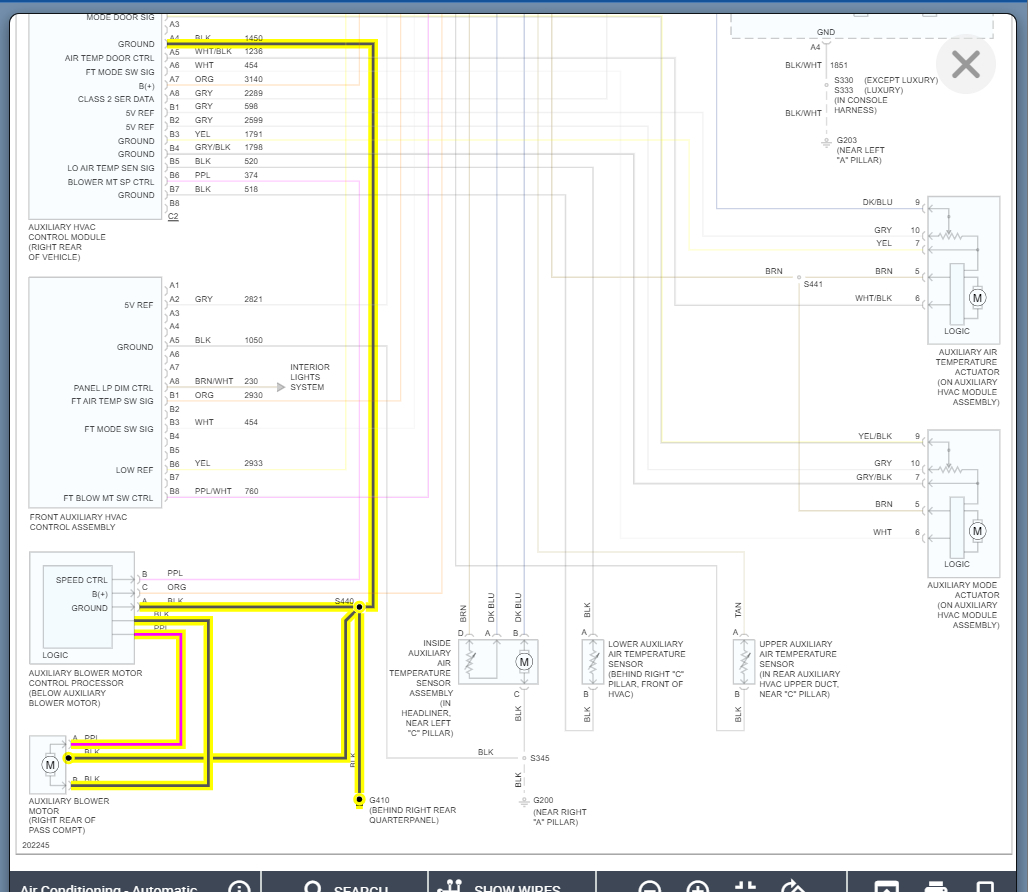
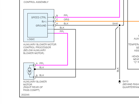
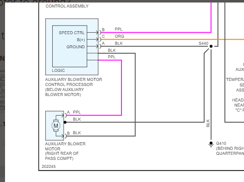
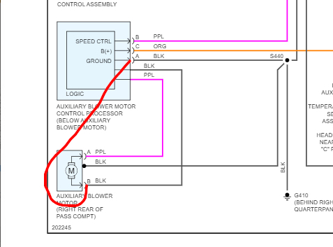
Use the diagrams attached to this post not the previous ones.

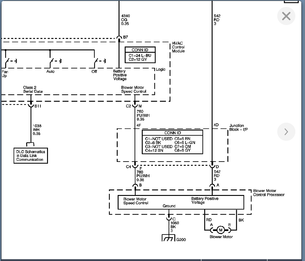
1) You should have battery voltage on pin A of the blower motor processor.

2) Then when checking voltage from pin A to pin C you should have battery voltage.

3) Then when checking pin B to Pin C your voltage should vary depending on the fan speed setting. I think the lower the voltage the higher the speed. 3 volts should be high but check that by monitoring this voltage and change the fan speed. The slower the speed, the higher the voltage should get.

Lastly, are the motor wires themselves.

4) Check the red wire to pin c of the processor and when on high, it should be 12 volts.

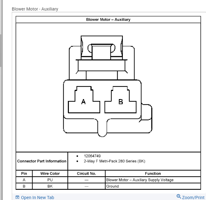
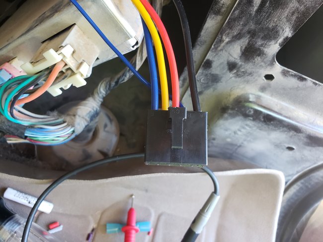
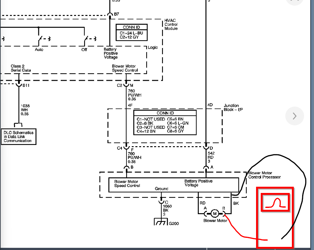
5) Then check the ground back to the motor by checking voltage from pin A to B of the motor connector. You can back probe this across the motor.

I suspect number 5 is the issue. So, we need to check the resistance (ohms) from the motor back to the processor. Basically, you are checking just the wire to see if it is a complete intact wire. So, unhook the connectors at the motor and processor and check from terminal to terminal of the black wire.

I think you said this is not doing anything even when you put it on the tone. If there is no tone, then that means there is no continuity.

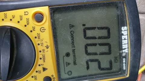
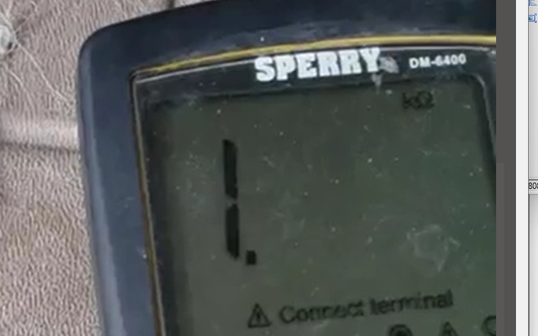
However, your meter should read OL which means out of limit or that is an open circuit.

Can you set this up and then send a picture or quick video of the meter?

If this is the case, then that will explain why when you ground this wire, the motor runs. It is because the wire that the motor uses when you are not applying your own ground is open or has high resistance. So, the circuit is not complete.

Hopefully, this makes sense.
Jun 18, 2022 at 1:49 PM
Avatar
ELMERMAXX
  • MEMBER
  • 20 POSTS
1 A on Module zero volts.
2 A>C 14.35 volts.
3 B>C high 3.25 then drops to .025.
Low exact same readings.
4 A>B zero voltage on motor connector.
5 ohms test between B on motor connector and A on module no change on meter at all.
Jun 18, 2022 at 4:55 PM
Avatar
ELMERMAXX
  • MEMBER
  • 20 POSTS
The video was testing a piece of wire to test meter function the actual test there was no change.
Jun 18, 2022 at 4:58 PM
Avatar
KASEKENNY
  • CERTIFIED EXPERT
  • 18,907 POSTS
Okay. So, on number 4 when you measured voltage across the motor you had 0 volts.

Let's confirm this one more way. Measure the voltage from A on the motor to C on the module or a known good ground. If you have battery voltage when on high, then that confirms you have no ground from B on the motor back to the module.

Which means I want to clarify when you say there was no change when you checked the ohms on the actual wire.

Does that mean it was the same (no change) as the test wire? The test wire read .001 kohms. That means it was one tenth of an ohm which is perfect amount of resistance on a wire. If that is what this wire on the vehicle read then that is ok.

If your meter reads this shown below when checking this wire from the motor to the module, then that means it is an open circuit and you have a broken wire.
Jun 18, 2022 at 5:22 PM
Avatar
ELMERMAXX
  • MEMBER
  • 20 POSTS
I checked for voltage while fan was on high between A on the motor and a good ground and there was14.45 volts.
Yes, there was no reading from the ohms test between A on the module and B on the motor connection.
Any idea as to where the broken wire might be located at?
Jun 19, 2022 at 9:48 AM
Avatar
KASEKENNY
  • CERTIFIED EXPERT
  • 18,907 POSTS
Unfortunately, that I cannot tell you. The best bet is to cut the wire at both ends and just wire it into a new one of your own.

Here is a video that will show how to solder new wires. Basically, you want to cut about 2 inches from each connector and then run a new wire.

https://www.youtube.com/watch?v=PxA5wczsCVo

Obviously, the video is of a headlight connector, but the point is how to cut and solder in a new wire. You can use the connectors that he shows but they are not as good as soldering.
Jun 19, 2022 at 5:48 PM