Radiator fan (low and high speed) not turning on?

1998 FORD ESCORT
110,000 MILES • 2.0L • 4 CYL • 2WD • AUTOMATIC
Avatar
ALOHA168
  • MEMBER
  • 52 POSTS
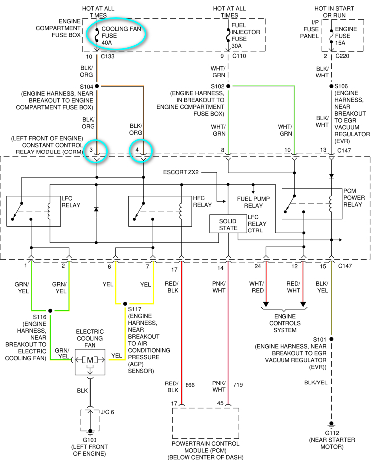
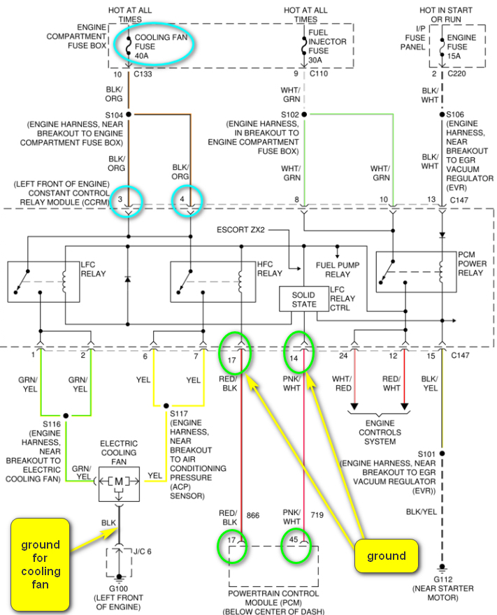
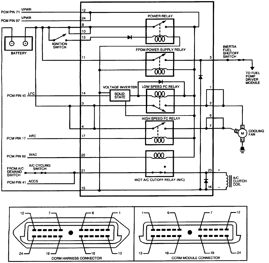
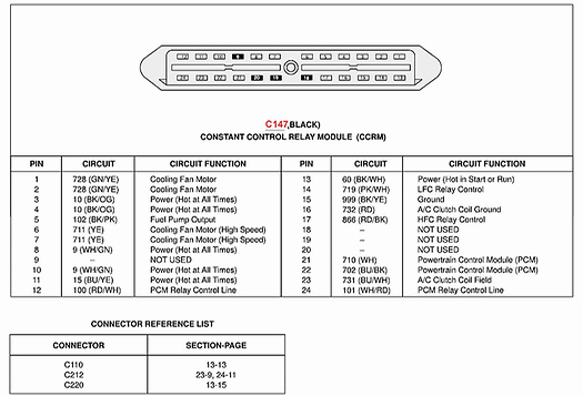
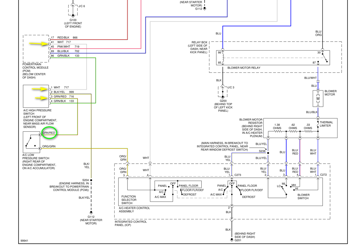
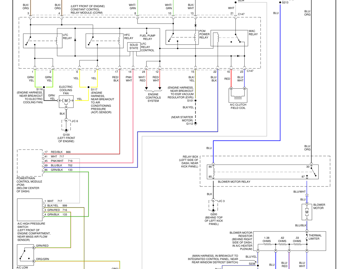
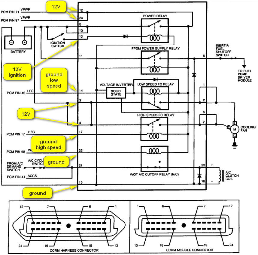
I replaced the coolant temperature sensor because I thought it wasn't turning on my fan when the temperature was reached. Actually, my old one was still good which I found out later. After I replaced it (plug and play job), it was very hard to start the engine so I hard to put the old one back. After that, my radiator fan (low speed) won't turn on again even when the temperature was reached. And I tried to turn on the A/C and I could see my A/C clutch did not engage nor the high-speed fan will turn on. I have removed the fan and tested the low and high speed with a 12V battery and they both work. I also tried to short out the 2 pins to the coolant sensor, but the low speed won't turn on. I have replaced the CCRM (Z refurbed by Cardone)) 2 times and nothing changed. I'm totally lost in troubleshooting this problem now. Could this be the PCM/ECM problem, or should I try with a genuine Z CCRM from a junk yard/eBay? If I replace the PCM, do I need to re-program it?
Mar 13, 2024 at 5:36 PM
Advertisement
Avatar
BORIS K
  • CERTIFIED EXPERT
  • 836 POSTS
Hello,

I would suggest first checking the cooling fan fuse, 40A, in the engine compartment fuse block.
This fuse supplies constant 12V to pins 3+4, black/orange wire, at the CCRM.
Check that the fuse is good and that you have 12V at both pins of the CCRM.
See image 1 below.

Regarding A/C compressor not kicking in I suggest to first check air con fuse (15A) in instrument panel fuse block.
This fuse supplies ignition 12V on white wire to the A/C control panel
The A/C control panel supplies 12V out at orange wire to the A/C low pressure switch.
If there is sufficient refrigerant in the A/C system this switch will output the 12V on green/red wire to the PCM pin 41 and to the WAC relay in the CCRM module.
I suggest checking that there is 12V at the A/C control panel when the AC is switched on that there is 12V at the orange wire at the A/C low pressure switch.
check that there is 12V outgoing at the A/C low pressure switch on the green/red wire.
See image 2.

How to check voltage using either test light or voltmeter:

https://www.2carpros.com/articles/how-to-use-a-test-light-circuit-tester
and
https://www.2carpros.com/articles/how-to-use-a-voltmeter

How to check fuse:
https://www.2carpros.com/articles/how-to-check-a-car-fuse

How to test wiring:
https://www.2carpros.com/articles/how-to-check-wiring

Cheers, Boris
Mar 14, 2024 at 5:20 AM
Avatar
ALOHA168
  • MEMBER
  • 52 POSTS
I checked the 40A cooling fan fuse and the 15A AC fuse and both are good. I also got my 12V at pins 3,4,10 and 11at the CCRM (hot at all times). My main concern now is to get the low-speed fan to turn on when the temperature is reached. I'll work on the A/C (high speed) fan after the low speed is fixed. Since my low-speed fan doesn't turn on, does that mean the PCM is not sending the fan control signal to the CCRM (pin 14)? Please give me guidance on how to troubleshoot. I have not touched any of the existing wiring in my car except the connector at the CCRM for testing. I doubt that this is a Ground issue either. It all started after I tried to replace my coolant temperature sensor.
Mar 14, 2024 at 3:45 PM
Advertisement
Avatar
BORIS K
  • CERTIFIED EXPERT
  • 836 POSTS
Hello,

I would suggest checking the pink/white and red/black wires from the PCM to CCRM.
See image below.

How to test wire:
https://www.2carpros.com/articles/how-to-check-wiring

Also check if you apply a separate ground to pin 14 at CCRM if the low speed fan, then turns on. For this test the ignition needs to be on.

If it does and the wiring between the PCM and CCRM is intact, then this would point to a possible PCM issue.

A replacement PCM would require VIN programming.
I found a company which offers preprogrammed PCM.

https://carcomputerexchange.com/ford/escort/1999-ford-escort-2-0l-pcm-ecm-engine-computer/prod_1976.html

Cheers, Boris
Mar 15, 2024 at 4:04 AM
Avatar
ALOHA168
  • MEMBER
  • 52 POSTS
On checking the wiring between the PCM and CCRM, I need to figure out how to remove the center console. I could not find any videos online; do you have any procedure on this? On applying a Ground to pin 14 of the CCRM, do I do it with the CCRM unplugged or plugged in? It seems that the whole circuit all has to be connected in order for this to work. I'm a little confused here.
Mar 15, 2024 at 1:04 PM
Avatar
ALOHA168
  • MEMBER
  • 52 POSTS
Okay, I figured out how to apply Ground to pin 14 of the CCRM plugged in. I used a straightened paper clip and pushed it in from the other end of the plug. I pushed in about 1 inch into pin 14 and I could feel the metal inside. I tried this at pin 3 and 11 and I got 12V.With the ignition on and Ground touching pin 14, the low-speed fan still won't turn on. Does that mean my CCRM is bad? I scanned with my OBD2 scanner and there were no codes, and the engine runs fine, just the fans won't come on. Plus, I didn't mess with any wiring, so the chances of a bad PCM is very low. If I can't get this to work, can I make a circuit using the temperature sensor and a relay and wire directly to the low-speed fan just to get it to work temporarily?
Mar 15, 2024 at 2:11 PM
Avatar
ALOHA168
  • MEMBER
  • 52 POSTS
I opened up the radiator fan and checked for Ground at the connector terminals and I could find no Ground on any of the pins. I've found a picture of the connector online (attached). Is the black wire the Ground? My connector was all wrapped up and in a very tight space. According to the first picture you sent, it's BK and connects to J/C6, G100 on the left front of the engine. This is a very crowded area in my car, do you know where exactly/approximately it's at and what to look for?If I can't find it, can I just run a separate Ground wire straight to the connector? I hope this is my actual problem, if not, I'll have to start all over again.
Mar 17, 2024 at 4:37 PM
Avatar
BORIS K
  • CERTIFIED EXPERT
  • 836 POSTS
Hello,

Yes, the black wire at the cooling fan connector is the ground, see image below.
You could run a separate ground; this is often easier than trying to trace/find a break in the wiring.

Cheers, Boris
Mar 20, 2024 at 9:51 AM
Avatar
ALOHA168
  • MEMBER
  • 52 POSTS
I was wrong because I used a poor ground for reference. I checked again the next day with the battery ground and a bare metal chassis for reference and I could get a solid ground at the black wire. Well, back to square one again. I ordered a CCRM on eBay and it'll arrive this Friday. Hopefully this is it.
Mar 20, 2024 at 11:30 AM
Avatar
BORIS K
  • CERTIFIED EXPERT
  • 836 POSTS
Hello,

Thank you for the feedback, please let us know if you require any further assistance.

Cheers, Boris
Mar 21, 2024 at 5:09 AM
Avatar
ALOHA168
  • MEMBER
  • 52 POSTS
The CCRM came early today.After I installed it,I got exactly the same result as my original one.Neither low nor high speed fan would come on.I'm lost,can a 'reman' CCRM be bad or what else should I check?
Mar 21, 2024 at 12:57 PM
Avatar
ALOHA168
  • MEMBER
  • 52 POSTS
I applied a ground to pin 14 of the CCRM (with ignition in ON position) and the low-speed fan still doesn't turn on. I have constant 12V at pin 3. If the CCRM is good, shouldn't the low-speed fan turn on? Because we're not using the ground from the PCM. A little confused here. Or with the ground applied at pin 14 and ignition on,I should get 12V at pin 1 and 2?
Mar 21, 2024 at 5:46 PM
Avatar
BORIS K
  • CERTIFIED EXPERT
  • 836 POSTS
Hello,

The theory is with ignition on engine fuse (15A) in instrument panel fuse block provides 12V to pin 13, black/white wire, at CCRM.
This will trigger the PCM power relay which in turn supplies 12V to fuel pump relay, control inside CCRM (solid state relay), HFC relay and LFC relay.
The low-speed fan (LFC) control is via a commanded ground from the internal CCRM (Solid State) LFC control. This is applied externally from the PCM at pin 14 of the CCRM. The LFC relay is then switched on and supplies 12V out at pins 1+2, green/yellow wire.
The high-speed fan (HFC) relay is triggered directly by the PCM at pin 17 at the CCRM.
This then triggers the HFC relay and 12V is output at pins 6+7, yellow wire.

Cheers, Boris
Mar 22, 2024 at 2:36 AM
Avatar
ALOHA168
  • MEMBER
  • 52 POSTS
I connected a chassis ground to pin 14 of the CCRM with the ignition ON but I still got no 12V at pin 1 or 2. This should eliminate a PCM problem, correct? I look at the CCRM diagram, pin 14 goes to solid state(LFC relay control) which connects to 1 side of the LFC relay coil, and the other side is connected to pins 12 and 24(engine control system) which should be a 12V in order to operate the LFC relay so that it will connect pin 3/4 12V to pin 1/2.Does that mean the solid state inside the CCRM is bad? What should I get at pin 12/24 with the ignition on? This is a 'reman' CCRM from A1 Cardone, they're supposed to test it at the factory before they sell it to the customer and let them do the testing.
Mar 22, 2024 at 3:05 PM
Avatar
ALOHA168
  • MEMBER
  • 52 POSTS
Since my fuel pump is working which is powered by the fuel pump relay which connects to pin 12/24. And I manually connect a ground to pin 14 which connects to the solid state. Does this narrow down to a defective solid state? How does this solid state function?
Mar 22, 2024 at 5:47 PM
Avatar
ALOHA168
  • MEMBER
  • 52 POSTS
I ordered a CCRM from a junk yard (from a working car) that looks exactly like my original one. After installation, it works the same as my original and the A1 Cardone one and my fans are still not working. I tested my CCRM connector(unplugged) for voltages/grounds/continuity and I got all the expected results. Now I doubt the problem is with the CCRM.
Mar 28, 2024 at 2:02 PM
Avatar
STRAILER
  • CERTIFIED EXPERT
  • 53,854 POSTS
You are losing power are ground somewhere I would go over the wire testing guide above and the wiring diagrams Boris has provided to double check and test the power and grounds. I don't think there is a problem is with the CCRM. There must be a wire that is broken or a bad connection.
Mar 30, 2024 at 10:32 AM
Avatar
ALOHA168
  • MEMBER
  • 52 POSTS
I need to check my coolant temperature sensor again.I searched online but found different values.Can you give me the correct resistance from 32 degrees F to room temp and 212 degrees F?
Apr 4, 2024 at 4:03 PM
Avatar
ALOHA168
  • MEMBER
  • 52 POSTS
Also this sensor senses various voltages from the PCM. What is the proper procedure for this test?
Apr 4, 2024 at 4:14 PM
Avatar
STRAILER
  • CERTIFIED EXPERT
  • 53,854 POSTS
They don't give us those tests in Alldata, but I do know that if you over tighten the sensor, it can break internally. I would get a new sensor and compare the two. Check out the images (below). Let us know how it goes.
Apr 5, 2024 at 9:01 AM
Avatar
ALOHA168
  • MEMBER
  • 52 POSTS
I have tested the wiring between the PCM and CCRM and ECT.All modules unplugged and battery disconnected.I found PCM pin 71 was actually connected to CCRM pin 24.And PCM pin 97 was also connected to CCRM pin 24.CCRM pin 12 and 24 are connected internally.Everything else checked out good EXCEPT PCM pin 41 to CCRM pin 21 which I found it OPEN.I checked the wire from both ends and they have the same color and gauge which means it should be a straight wire.Could it be a fuse inside blown causing this OPEN?Pin 21/22 of CCRM is for the AC clutch.Should I just run a new wire to replace it?
Apr 11, 2024 at 6:56 PM
Avatar
ALOHA168
  • MEMBER
  • 52 POSTS
Sorry,I attached the wrong picture.This is the correct one.
Apr 11, 2024 at 6:59 PM
Avatar
ALOHA168
  • MEMBER
  • 52 POSTS
Hi Boris,

I went back to the first step you posted using image1 and image2 for testing again. I have replaced my PCM and CCRM (exact same models like my original ones) from eBay. I have constant 12V at pin 3&4 of the CCRM.I have 12V at pin 13 CCRM with ignition on. I have solid Ground at pin 15 CCRM and my radiator fan connector. I have continuity on pink/white and red/black between PCM to CCRM(pin 45 PCM to pin 14 CCRM, pin 17 PCM to pin 17 CCRM). However, with ignition on, I can't turn on Low/High speed fans by connecting Ground to pin 14 or pin 17 of the CCRM. With ignition on and A/C switch set to on, I was getting 12V at the orange wire at the AC low pressure switch, but there's no 12V at the Green/Red wire next to it. In order to get 12V to this wire, does the AC compressor(clutch) has to be engaged and spinning? Another discrepancy that I found was: this green/red wire which goes to pin 41 of the PCM, but the wire at my PCM pin 41 was white (which was working before). Can you give me more guidance? Thank you.
Apr 19, 2024 at 4:48 PM
Avatar
STRAILER
  • CERTIFIED EXPERT
  • 53,854 POSTS
Did you check the wiring connections with the guide and wiring diagrams? do you have power and ground? then there are the components you have replaced? can we please double check these?
Apr 20, 2024 at 9:08 AM
Avatar
ALOHA168
  • MEMBER
  • 52 POSTS
Hi Ken or Boris,

I have replaced my PCM and CCRM (exact same models like my original ones) from eBay and I'm getting the same results (fans not working). on checking the wiring, voltage and ground, everything checked out except the green/red wire at the A/C low pressure switch. This wire should go to PCM pin 41(image1),but the wire at my PCM pin 41 is white instead???And i looked at the PCM connector(104 pins) and couldn't find any green/red wire? I don't know where that wire goes from the ac low pressure switch to. But whatever it is, this setup was from the factory and working before. Can anyone of you give me some more guidance? Thanks.
Apr 21, 2024 at 2:09 PM
Avatar
BORIS K
  • CERTIFIED EXPERT
  • 836 POSTS
Hello,

I searched the technical information system again and found a slightly different wiring diagram. This one shows a white wire at pin 41originating from the AC high pressure switch pin 1.

See images below.

Hope this helps.

Cheers, Boris
Apr 22, 2024 at 1:18 AM
Avatar
ALOHA168
  • MEMBER
  • 52 POSTS
Hi Boris,

The green/red wire between the AC Low and High switch was tested good in continuity. The White wire between the PCM and AC High pressure switch was good as well. I also have Ground at the Black/Yellow wire at the AC High pressure switch. The green/black wire between the PCM and AC High pressure switch was good too. I also used an electrical contact cleaner to clean the connectors before I plugged them back. The rest of the wiring between PCM and CCRM I've already tested 2 to 3 times already. After testing, I reconnected the battery and started the car and my fans are still not working. I'm pretty sure this is not a wiring problem anymore. The PCM and CCRM are the OEM units I bought at eBay which are supposed to be good, and they both behave like my original units. Could this be the CCRM 'solid state relay? I read online that a Ford mechanic mentioned that the ECT sensor is a Sensor, not a switch. If we short the 2 pins to turn on the radiator fan, it will damage the PCM. But I've already replaced the PCM and it's still the same. I've used boiling water to test my original sensor and it was within Ford specs and I installed it back on my car. Any new ideas?
Apr 22, 2024 at 6:45 PM
Avatar
BORIS K
  • CERTIFIED EXPERT
  • 836 POSTS
Hello,

The ECT sensor is not a switch, quite correct
It is a NTC resistor, Negative Temperature Coefficient, meaning that the resistance decreases with temperature increase.

A good read:
https://www.2carpros.com/articles/how-a-coolant-temperature-sensor-works

Have you tried manually switching the CCRM, simulating switched ground inputs?
This would be at pins 14+17, apply ground to either pin with ignition on.
Does the fan switch on, on either speed?

Cheers, Boris
Apr 23, 2024 at 3:51 AM
Avatar
ALOHA168
  • MEMBER
  • 52 POSTS
On applying Ground to pin 14 and 17 with ignition ON,I tried that on all the CCRM's I bought and none worked.I don't think ALL of them can be bad(same symptom).I don't know what else I should try.Do you know how to test the ECT sensor voltages on the car with engine running?
Apr 23, 2024 at 10:19 AM
Avatar
ALOHA168
  • MEMBER
  • 52 POSTS
If I use image1, connecting a Ground to pin 17 of CCRM with ignition ON,I should be able to turn on the High-speed fan because it doesn't go through the solid state anyway, but I can't. This is strange and all 3 CCRM's behave the same.
Apr 23, 2024 at 2:44 PM
Avatar
ALOHA168
  • MEMBER
  • 52 POSTS
I've tried just about everything on this car and nothing will turn on my fans.
Oct 28, 2024 at 1:37 PM
Avatar
BORIS K
  • CERTIFIED EXPERT
  • 836 POSTS
Hello,

I have read back on all the information given.
I have consulted the diagram you have supplied and marked the pins I believe are responsible for the cooling fan activation.

On CCRM pins 8, 10, 11 should also have constant 12V.
Pin 21 would be a 12V switched from PCM.

Please see below.

Cheers, Boris
Oct 29, 2024 at 4:20 AM