Power doors wiring

2001 CHEVROLET SILVERADO
140,000 MILES • 8.1L • V8 • 4WD • MANUAL
Avatar
TERRY LEMON
  • MEMBER
  • 22 POSTS
my truck has manual windows and locks. i swapped front doors with power windows and locks from a 2003 Tahoe.
how do i wire it so widows work (powered locks would be nice but not necessary)?
Dec 6, 2019 at 2:32 PM
Advertisement
Avatar
CARADIODOC
  • CERTIFIED EXPERT
  • 34,306 POSTS
Assumming you also transplanted the door panels with the switches and wiring harnesses, the driver's door only needs two wires for that window to work. One is the ground wire and the other is the 12-volt feed. That should be tied to the fuse box to a point that goes dead with the ignition switch off. If wired direct, there is always the liability risk if water drips into the switch, creates carbon between the contacts, then starts a fire.

I'm going to find a diagram for the 2003 model and post that for you, but in the meantime, tell me what came with the doors. Did you get the wiring harness that goes through the door hinges on one or both sides? If not,for just the windows, you'll need to run two wires from the driver's switch over to the passenger's switch. Do you also have two rear windows?

We'll worry about the locks later, but if you're going to run wires before I get back tomorrow, run a pair for the locks right away so you don't have to do that part of the job twice. Make life easier on yourself by using different colors, or use labels so you can tell them apart easily.
Dec 6, 2019 at 7:16 PM
Avatar
TERRY LEMON
  • MEMBER
  • 22 POSTS
the doors are complete with panels ,switches they have controls for heated seats ,locks and window locks,mirrors, foot controls adjustments and 4 window controls and speaker. also first and second the truck i put the doors on is a extended cab ,just the driver and passenger front doors have roll up windows.
i just want windows ,locks and speakers to work.
i need to know what wires from door harness goes to windows ,locks and where to connect to truck.
i am very mechanically inclined but am not real good with electrical issues (i don't want to let the magic smoke out, LOL).
so i need easy to follow diagrams.
Dec 7, 2019 at 6:55 AM
Advertisement
Avatar
TERRY LEMON
  • MEMBER
  • 22 POSTS
correct the previous post.
First and second driver controls.
and doors have complete harness.
Dec 7, 2019 at 6:59 AM
Avatar
TERRY LEMON
  • MEMBER
  • 22 POSTS
the truck i am putting the doors on is a 2001 2500 HD Silverado 5 speed manual 4x4.
Dec 7, 2019 at 9:15 AM
Avatar
CARADIODOC
  • CERTIFIED EXPERT
  • 34,306 POSTS
Well, I stand corrected. Starting in 2002 on some GM truck models, they built the Body Computer into the radio to insure it couldn't be replaced with an aftermarket unit. Along with that, the insane engineers lost all track of common sense when it came to designing electrical circuits. The power window circuits that worked fine for over 70 years now have to include multiple computers. In fact, every window switch is a computer module on 2003 models. In the past, a switch with multiple contacts inside ran a window. Today, the switch sends a signal to the built-in computer circuit, then that computer performs the switching functions and runs the motor, but only if approved by the Body Computer. It is not practical to try to transplant the 2003 Body Computer into your truck because it is part of a team that includes the instrument cluster, the door modules, and the Engine Computer. Those door modules run the power lock motors. Those also used to be real simple and reliable, but no more.

What I would recommend as the first approach is to see if you can find window switches from an older GM truck model that will fit in your door panels, then I'll draw up a diagram for you on how to wire them. Regardless of the year, all power window motors run on 12 volts. We need to find switches that didn't have small relays attached to them. That way the internal contacts will be large enough to handle the current directly.

If that is not an option, there is a three-position, center-off, spring-loaded switch listed on eBay that is perfect for this application, but I'll have to check if it will handle the current. You'd have to cut about a 1 1/4" square hole in the door panel, and have about two inches of clearance behind it. That switch will also work for the power locks.

When you're in the salvage yard, harvest the rubber accordion boots the wires run in between the door hinges. Also look for a 30-amp thermal circuit breaker in an under-hood fuse box. Because windows are considered a safety system, fuses are not used because if an intermittent short occurs, a blown fuse is permanent. Thermal circuit breakers reset automatically after a few seconds, so in an emergency, it's possible for the windows to work again.

It's a good idea to use a circuit breaker for the power door locks too. GM used to be good about placing accessory 12-volt terminals in their fuse boxes for add-ons, but they really aren't meant for circuits that draw a lot of current. It's better to run the fused wire right to the circuit already in the fuse box for power windows. We might have to rob the terminals out of a fuse box in the salvage yard. To save a few pennies, they might have been left off on the assembly line since that wasn't an installed option on your truck.

The web site we use for online service manuals is running frustratingly slow today so I can't look at wiring diagrams for earlier years. I'm going to have to dump this on you for now to check in the salvage yards to see if you can find switches that will pop into your door panels. Start with the 2001 models. I'll let you know when I find some years that will work.
Dec 7, 2019 at 2:47 PM
Avatar
CARADIODOC
  • CERTIFIED EXPERT
  • 34,306 POSTS
These first two diagrams are of the window circuit for a 2003 model. If you look closley, you'll see all kinds of references to computers and drivers. It looks like they retired all the engineers who knew how to design window circuits without needing computers.

The third diagram is for a 2001 Tahoe. You'll notice there are no computers or relays associated with the driver's switch. Gee whiz engineers; how could this circuit have possibly worked?! There are a pair of relays in the passenger's switch. I don't know why they felt they needed them there unless the switch cointacts were too wimpy to handle this much current.

The fourth diagram is for a 1999 Tahoe, and it looks identical to that for a 2000 model. While it may look complicated, I think we can work with this one. Look for these switches in the salvage yard, and get the plugs that go with them ,and the entire wiring harnesses if possible. It is too much work to pull the entire harness that goes across the dash unless the dash has already been removed. You will have to run two wires from the driver's switch to the passenger's switch, and a third one if you want the "lockout" switch to work. If you don't care about that, the third wire just has to run to the 12-volt source at the fuse box, (same place we'll be connecting the 12 volts for the driver's switch).

If you get enough of the harnesses to run through the door hinges, be sure to unwrap them, then inspect each wire for signs of cracking insulation, or even completely broken wires. That is a common failure. If you see that, cut each wire back far enough for the splices to be inside the door and inside the "A"-pillar. That way they;ll be in areas that don't flex when you open the door. Also, when I do these repairs, I splice in pieces of wire just over twice as long as what I'm removing, and I wind up the extra inside the "A"-pillar. That way when this repair has to be done again, I can pull that extra out and the job is already done on one end.

Slide the strands into each other, solder the splices, then seal them with heat-shrink tubing with hot-melt glue inside to seal out moisture. All the auto parts stores carry that stuff now.
Dec 7, 2019 at 4:00 PM
Avatar
TERRY LEMON
  • MEMBER
  • 22 POSTS
thanks for the information, with it this close to Christmas, i will be working a lot. I don't know when I will get a minute to try it. I will let you know what i find. Thanks
Dec 7, 2019 at 5:45 PM
Avatar
TERRY LEMON
  • MEMBER
  • 22 POSTS
i think you have the right idea, using a older switch, I will look at that option after Christmas is over. too busy at work right now .
I will let you know how it works out. Thank you for your help.
Dec 7, 2019 at 5:53 PM
Avatar
CARADIODOC
  • CERTIFIED EXPERT
  • 34,306 POSTS
If I get the chance, I'll visit some of my local yards to see what I can learn about these models and years. I may post some follow-up replies with wondrously valuable information, mainly to keep this fresh in my mind so I don't have to start all over. Have a dandy Christmas, and let me know when you're ready to continue.
Dec 8, 2019 at 1:52 PM
Avatar
TERRY LEMON
  • MEMBER
  • 22 POSTS
thank you.
Dec 9, 2019 at 9:44 AM
Avatar
TERRY LEMON
  • MEMBER
  • 22 POSTS
found this on Amazon, what do you think?
Dec 9, 2019 at 11:25 AM
Avatar
CARADIODOC
  • CERTIFIED EXPERT
  • 34,306 POSTS
From what I can tell, those are of the proper design we need, but only if you don't have the cutout in the door already for original switches. And be sure there's enough clearance behind the door panel before you chop a hole in it.

Here's a photo of what I was looking at on eBay. The item number is 362597851109. These are rated for more current than your motors will draw.

The advantage to what you found is you have all the connectors pre-wired, so it's just a matter of plugging everything in, and running the wires. The disadvantage is you don't have to understand how the circuit works, so troubleshooting could be impossible, and you won't need the help of my genius.
Dec 9, 2019 at 6:09 PM
Avatar
TERRY LEMON
  • MEMBER
  • 22 POSTS
LOL,i certainly would not like to be without the benefit of your genius, however with that being said,i think I will go for the easy route.
Dec 10, 2019 at 8:57 AM
Avatar
CARADIODOC
  • CERTIFIED EXPERT
  • 34,306 POSTS
Dandy. Keep me posted on your progress and on what it takes to get this done.
Dec 10, 2019 at 5:22 PM
Avatar
TERRY LEMON
  • MEMBER
  • 22 POSTS
got a quick question, i am trying to figure out what lock switch to order.
do i need a 3 pin ,4 pin or 5 pin switch for to door locks?
Dec 14, 2019 at 6:26 PM
Avatar
CARADIODOC
  • CERTIFIED EXPERT
  • 34,306 POSTS
Typically there's four terminals on the driver's switch for the driver's window. Two go to the motor, one is the 12-volt feed, and one is the ground, but that one goes to multiple places inside the switch. The switch I showed in the photo has six terminals. That will work for both windows. Two opposing corners are tied together, creating one wire connection. The other two opposing terminals are tied together, creating the second wired terminal. Those two wires go to the motor. For the two center terminals, one gets 12 volts and the other goes to ground. In effect, you have four terminals and four wires going to that switch.

The passenger's switch in the driver's door typically also uses four terminals. One gets 12 volts, one is grounded, and two run to the passenger's switch on their door. The switch on the passenger's door has five terminals. Those two wires from the driver's side are two of those terminals. Two go to the motor, and the fifth one gets 12 volts. That 12 volts could come from the lockout switch on the driver's switch assembly, if used. There's no ground terminal in the passenger's switch. Both ground circuits travel back on the two wires over to the driver's side passenger switch, through it, then to ground over there.
Dec 15, 2019 at 2:51 PM
Avatar
TERRY LEMON
  • MEMBER
  • 22 POSTS
unless i misunderstood, you are talking about window switches.
i was asking about lock switches.
Dec 15, 2019 at 3:29 PM
Avatar
CARADIODOC
  • CERTIFIED EXPERT
  • 34,306 POSTS
Oops. That was my mistake, but I'll never admit it.

I'm going to have to think about this for a few minutes. Here's the diagram for my '88 Grand Caravan. The switches became simpler in later years on other brands, but the wiring became a lot more confusing at the same time. They use relays on a lot of models, but then those relays run the lock motors through many more wires than before. For the more common sense switching, this diagram is typical.

There's six terminals, but two are common inside the switch, so they're tied together. That means there's just five wires going to each one. The rest of the circuit is different though compared to the power windows. With the windows, you're running just one window at a time, but from two places with the passenger's window. With the locks, you're always running all three from either front switch. (No switch on the sliding door).

I'll draw a diagram tonight to show how this circuit works, then I'll be back later to post it.
Dec 15, 2019 at 4:55 PM
Avatar
TERRY LEMON
  • MEMBER
  • 22 POSTS
waiting on pins and needles for your genius to be revealed. LOL
Dec 15, 2019 at 5:16 PM
Avatar
TERRY LEMON
  • MEMBER
  • 22 POSTS
do you think this will work for the locks?
Dec 16, 2019 at 6:26 AM
Avatar
TERRY LEMON
  • MEMBER
  • 22 POSTS
i just ordered a couple of 5 pin switches for the locks.
Dec 16, 2019 at 9:40 AM
Avatar
TERRY LEMON
  • MEMBER
  • 22 POSTS
i think i am going to go with this one for the locks.
Dec 16, 2019 at 9:44 AM
Avatar
CARADIODOC
  • CERTIFIED EXPERT
  • 34,306 POSTS
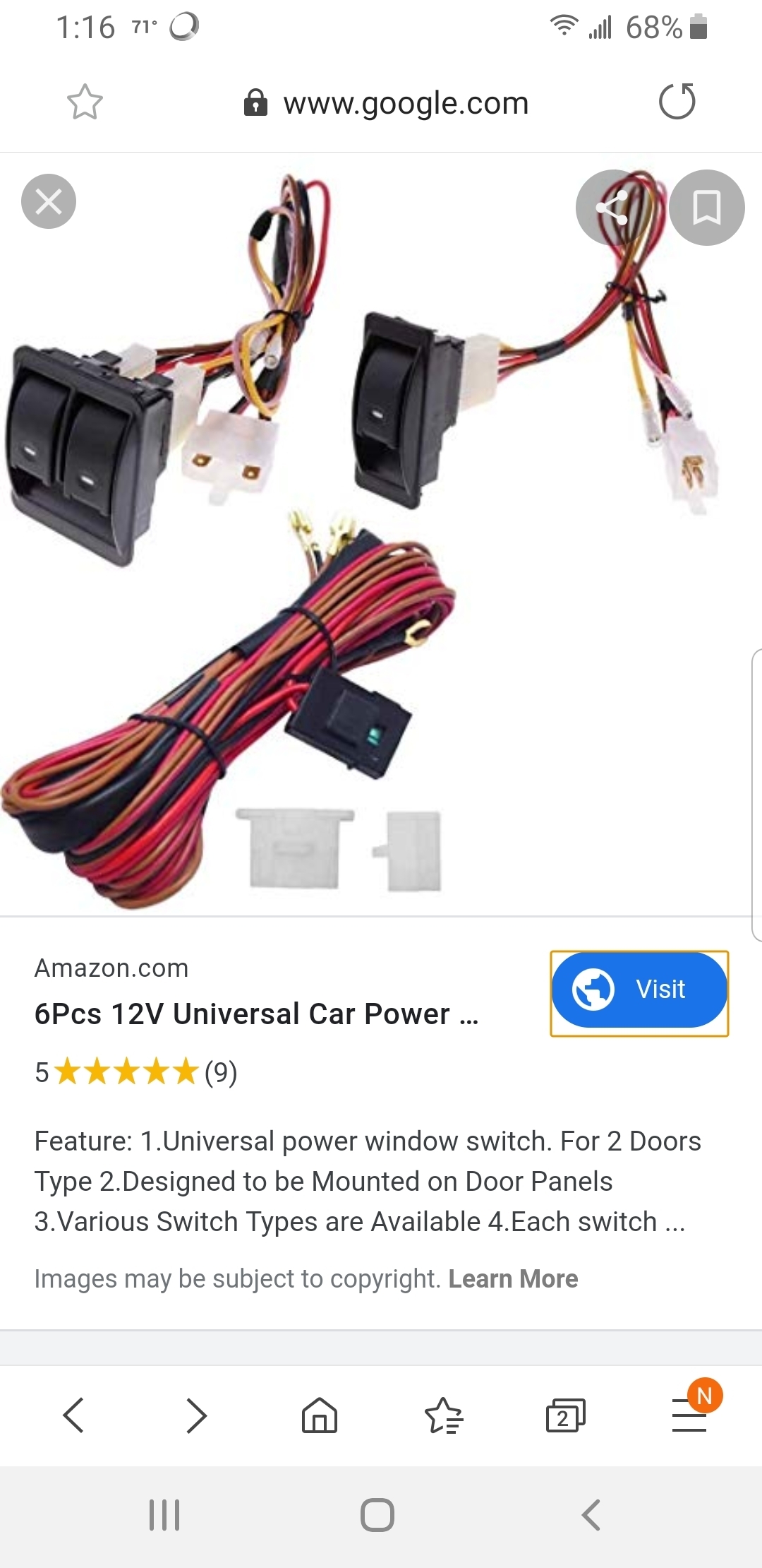
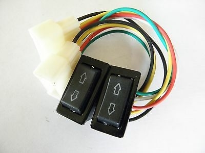
The first item you posted is listed for "vehicles with central locking system", which I take to mean is systems with remote key fobs. With those, there is no one to press a physical switch inside the vehicle, so there has to be a computer module with a receiver, that runs a pair of relays. Door switches to work with these systems have only three wires; a 12-volt feed, one to run the "lock" relay, and one to run the "unlock" relay.

I put together a description of how the older lock systems work. It shows how the door switches are both in the circuit when either one is pressed. This description is rather cumbersome, and it makes more sense when it's explained with an overhead projector, but see if you can get something useful out of it.

Power Lock Operation

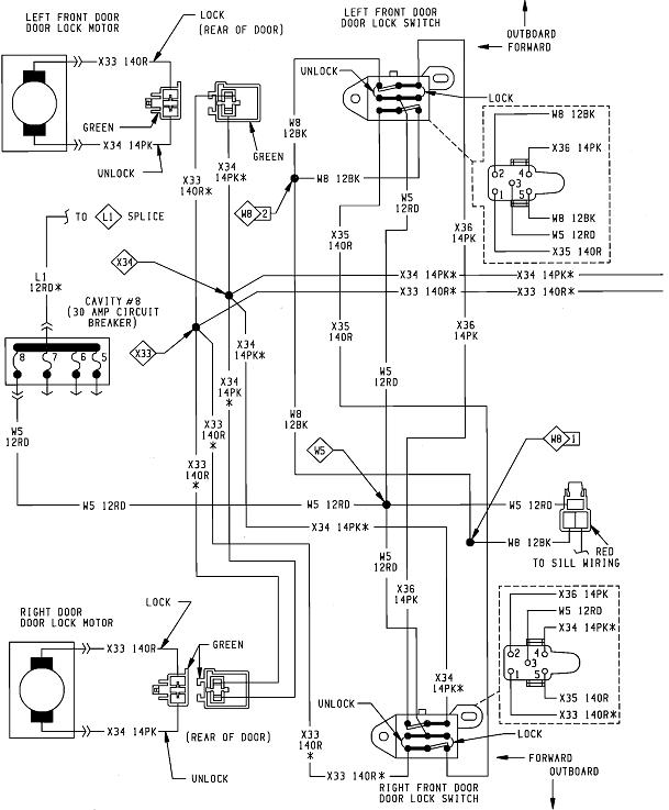
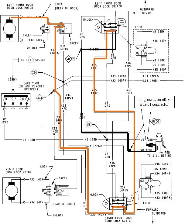
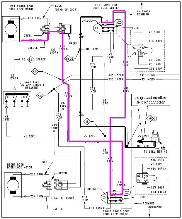
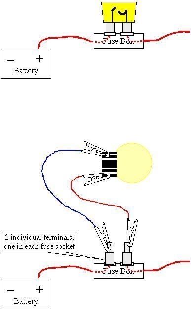
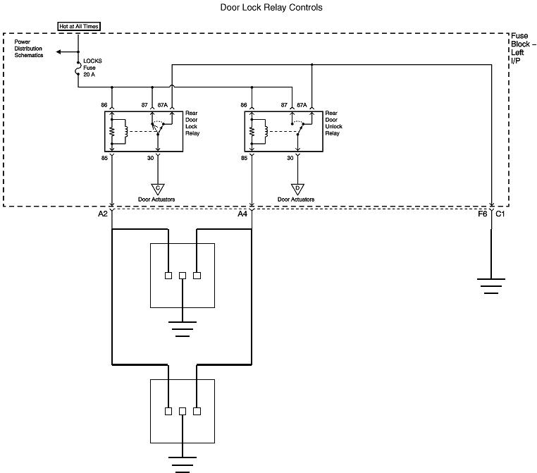
The first diagram is for the complete circuit in an '88 Grand Caravan except for the lock motor for the sliding door. Circuits X34 14PK and X33 14OR at the center, right side go to that lock, and those two wires would be used for both rear lock motors on four-door cars or trucks. This circuit is typical for most car brands and models up to the mid '90s.

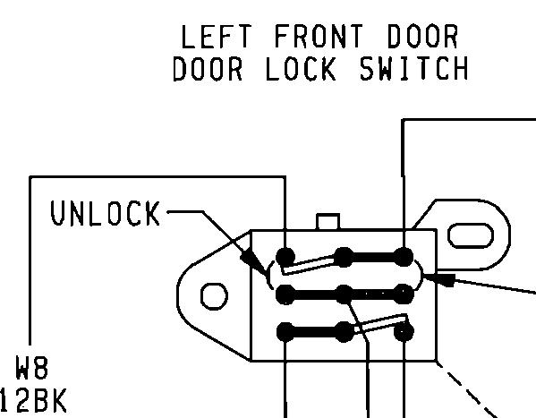
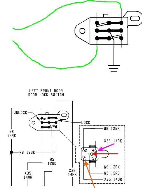
Look first at the top of the second diagram. That is just one switch expanded for clarity. The switch has two independent double-throw switches built in. The green arrow is pointing to one of the movable contacts. There's no dashed line between the two movable contacts. That shows the two are not ganged together, so activating one leaves the other one alone in the released position.

Both switches are released. In the lower drawing, the blue line shows those contacts, and the red line shows that current can flow through them. The same is true for the lower contact, and current can flow through that pair of contacts too.

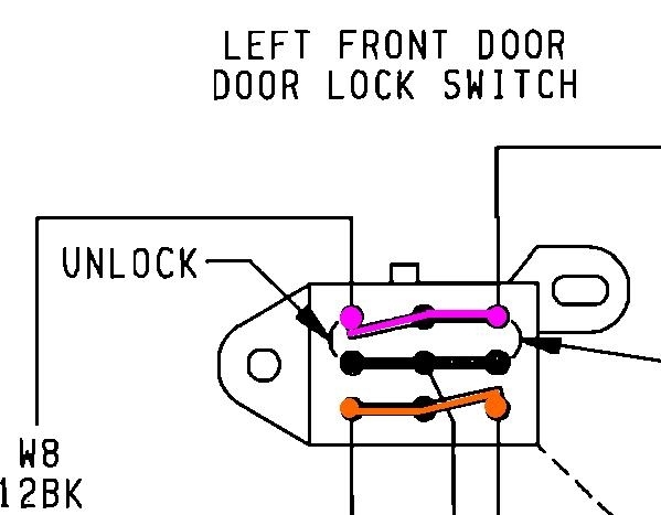
On top of the third drawing, the pink and orange lines show the two circuits and their four terminals. While the ground connection isn't shown on the first diagram, both of these circuits go to ground, through the two circuits in the other switch. Before we get to that, the important point is all four of those terminals must read continuity to ground. Note there's five wires connected to the switch. If you start out with a test light, you'll find one terminal has 12 volts on it. Regardless of how the terminals are arranged, once you identify the 12-volt feed wire, it's easy to know which other four wires must read continuity to ground.

At the bottom of the third diagram, the upper switch has been activated, as shown by the pink lines. The red line shows the path current takes, and note that it comes in on that fifth terminal.

Getting back to the released switch, in the fourth diagram, one half of the motor's circuit is shown with the orange lines. Start at the motor at the top left, then follow the path through the connector, down through splice X33, through the bottom half of the right door lock switch, then continues up through the bottom half of the left door switch. Once the path exits at the lower right terminal, it's a constant ground circuit as noted by the black lines. This shows that when both switches are released, the orange wire at the motor will read continuity to ground.

The other half of the circuit works the same way. In the fifth diagram, it is outlined with the pink lines. The point is everything has continuity to ground. A quick test is to unplug the lock motor, then measure from each wire in that plug, to ground, and you should find very low resistance. If you find an open circuit, there is a bad contact in one of the switches or a break in one of the connecting wires. Between these two circuits, there are a total of four contacts in use when both switches are released. This is why a defective switch can be the one that seems to operate the locks properly.

To be valid, those resistance tests must be done with the lock motor unplugged, otherwise, if there's a break in one circuit, the ohm meter will still read a real low value through the motor, then through the other circuit.

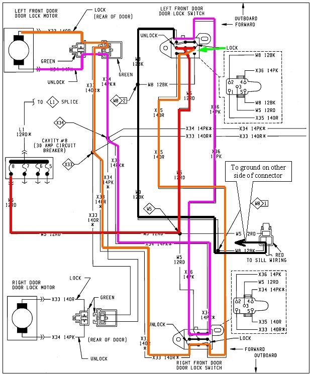
In the sixth diagram, nothing has changed in the pink circuit, so the top left lock motor's lower terminal is still grounded. The driver's switch has been pressed to the "Lock" position, as indicated by the green arrow. The orange contact has moved away from the ground contact at the lower right corner of the switch, them made the contact to the red 12-volt circuit. That places 12 volts on the entire orange circuit, including the top terminal on the lock motor. Once you follow the 12 volts through splice X33, it also shows up at all the other lock motors.

12 volts can also be placed on the orange circuit by the passenger's switch shown at the bottom of the diagram. That switch has 12 volts on its center terminal just like on the driver's switch.

The same type of operation occurs to unlock the doors. In this case, the orange contact would be released, and the pink contact at the top of the switch would break its connection to ground, then move to the 12-volt contact. That puts 12 volts on the lock motor's pink terminal while leaving the orange terminal grounded. The polarity of the voltage applied to the motor is reversed, so the motor runs the other way.

The reason this circuit can appear complicated is by designing it this way, if the driver and passenger each press their lock switch at the same time, nothing will be damaged. If they both press "lock", they'll both put 12 volts on the orange circuit, and the doors will lock. If one person presses "Lock" and the other person presses "Unlock", 12 volts will be placed on both the orange and pink circuits, so the difference between them is 0 volts, and the lock motors will do nothing. Also, to do that, each switch has first broken one of the ground paths for those two circuits, so there is nothing to short the 12 volts to ground.

Even if a short were to occur in the system, it is protected by an auto-resetting thermal circuit breaker. Power locks and power windows are considered safety systems, so they're protected by circuit breakers instead of fuses. A blown fuse is permanent until you can stop to replace it. The thinking is an intermittent short can render the system dead, but if that short goes away, such as right after the impact of a crash, it's possible for the circuit to work again once the circuit breaker resets. That can take as little as five to ten seconds.


To address your question about which switches to order, you can see those in these diagrams have five wires going to them, but that can be misleading. In the left door switch at the top of the diagram, the top left and lower right terminals both go to ground. They're tied together outside the switch, but they could be tied together inside the switch, leaving one less terminal to connect a wire to. They connected them externally because they can't be connected that way internally for the passenger's switch at the bottom of the diagram. Doing it this way means both switches can be of the same design and they'll work in either location. To leave off that one terminal would save very little cost but it would require building and stocking two different part numbers.

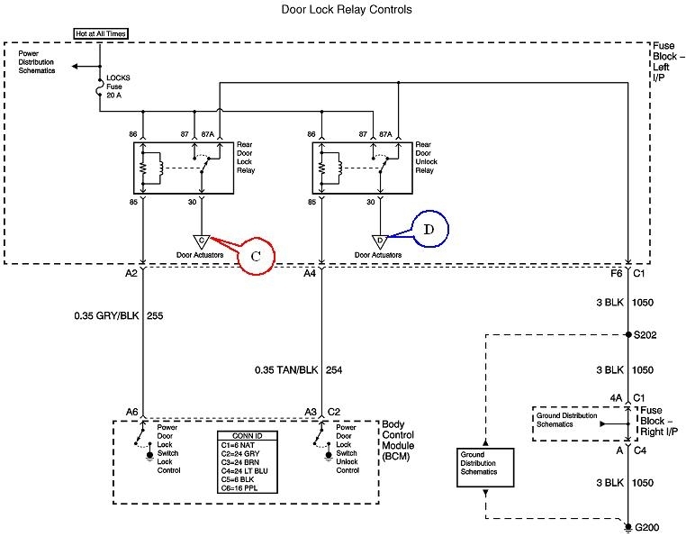
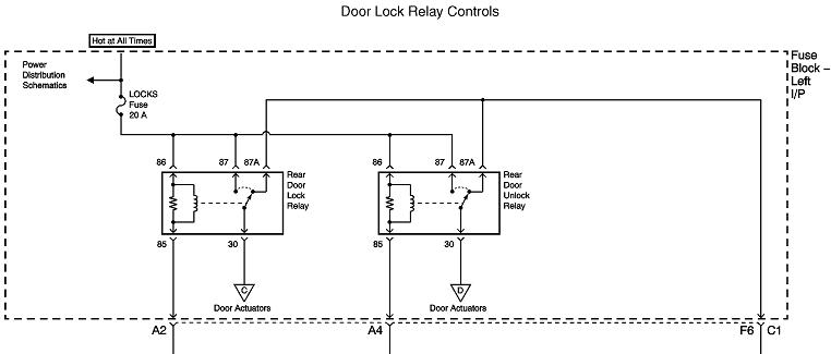
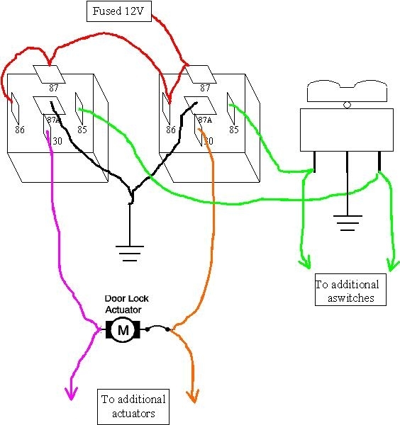
The next issue is the switching of polarity is done here by pressing a switch. In a lot of newer models, GMs in particular, the engineers can't seem to satisfy themselves with how complicated they can make a simple, reliable circuit. One of those complications is to do that switching with a pair of relays. The relay's contacts break a ground circuit first, then they apply the 12 volts to that circuit, just like the switches did. The relays are activated with a door switch of simpler design. All those need are the terminals for the 12-volt feed, a "lock" circuit, and an "unlock" circuit. Three wires to run a pair of relays.

You have to know how the aftermarket people are doing their switching to know which type of switch to order.

Be aware the circuit for the '88 Grand Caravan can not work with any type of remote keyless lock system. Those systems use a relay to put 12 volts on one of the lock motor circuits, but when the door switches are released, they're keeping those circuits grounded. Trying to put 12 volts on a circuit that's grounded will cause a short.

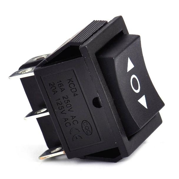
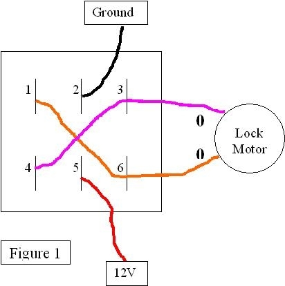
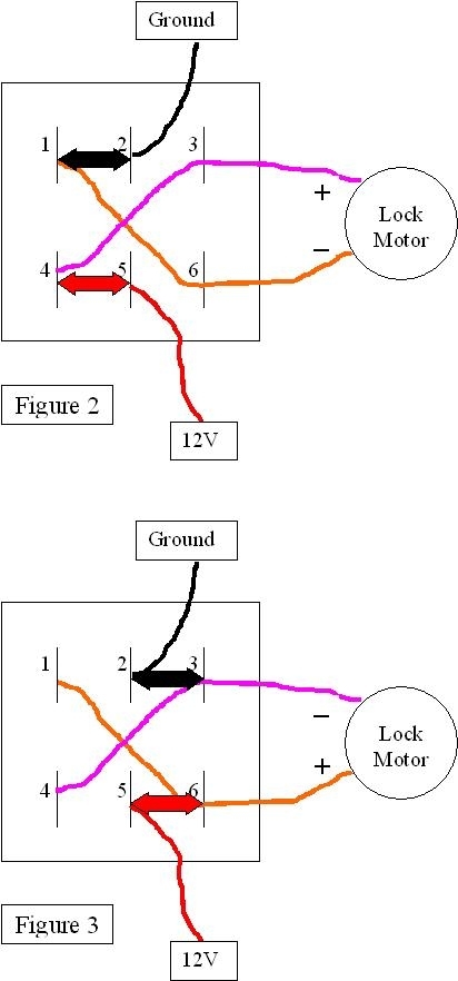
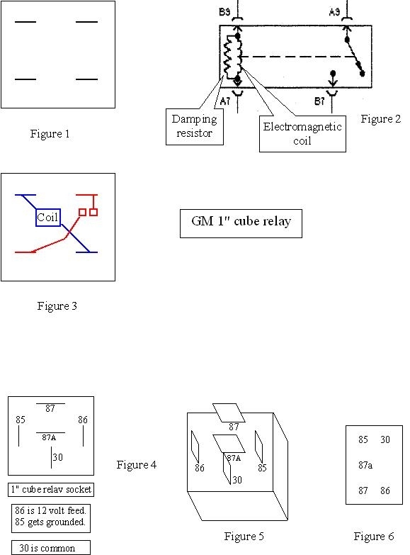
If it will help, I drew up diagrams to show how those switches I found on eBay would work. The terminals look like any standard double-pole, double-throw switch, but these are different. With a standard switch, you would find terminal 1 connected to terminal 2 at the same time as terminal 4 is connected to terminal 5, as in Figure 2. Flipping the switch connects terminals 2 and 3 together and terminals 5 and 6 together, as in Figure 3. You only have a choice of those two positions.

The switch you need has three positions with the center-off spring-loaded to stay in that position. When not being pressed, there's no connections between any terminals. When you do press it one way, the connections are as shown in Figure 2. 12 volts is applied to the pink wire on the lock motor and ground is connected to the orange wire. When the switch is pressed the other way, as in Figure 3, the pink wire is grounded and 12 volts is applied to the orange wire. The polarity is reversed at the lock motor.

The important point is in the original Caravan system, the switches keep both motor circuits grounded when they're released. When a switch is pressed, it removes one of the ground connections and puts 12 volts there.

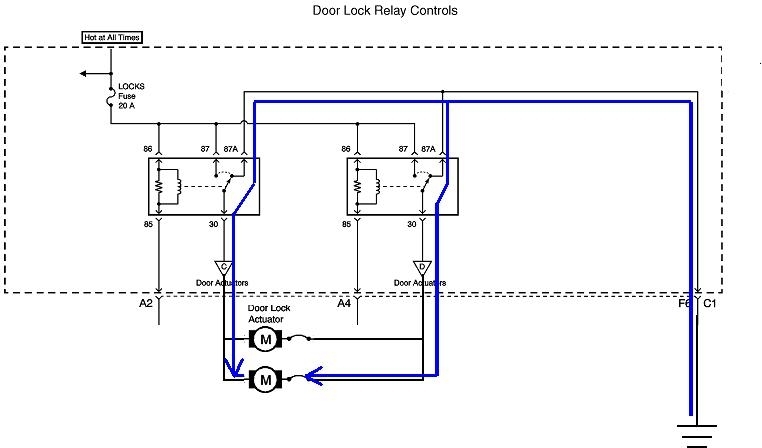
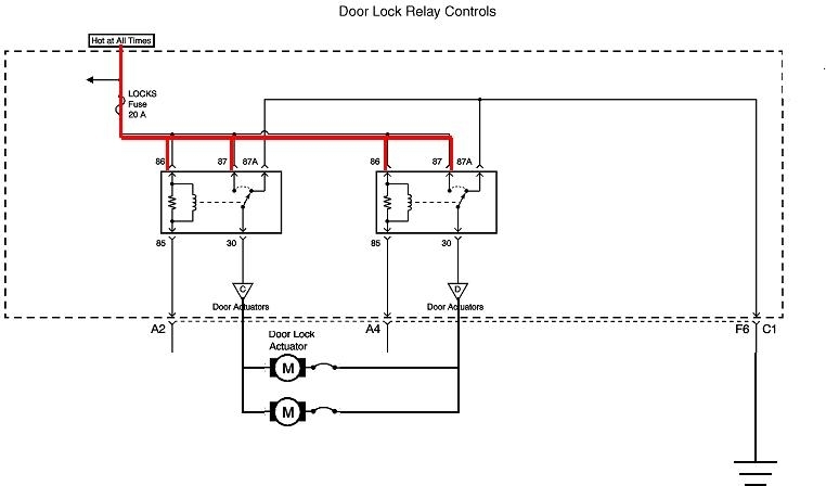
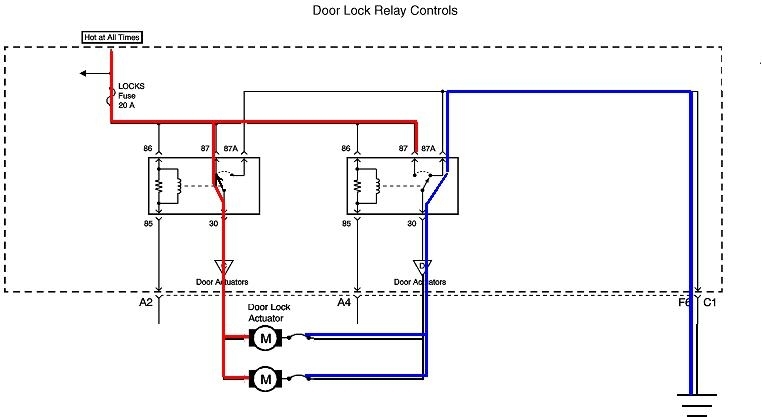
In the system using the switch in Figure 1, both circuits are open when the switches are released. When one of them is pressed, ground and 12 volts are switched on to the two circuits at the same time. Any number of switches can be added to the system, and one of them could be a pair of relays. Each relay can have two sets of contacts, one to switch on the ground, and one to switch on the 12 volts. Those relays can be operated by a remote key fob and receiver module. In this circuit, since no motor circuits are kept grounded, there will be no short to ground when one of the relays puts 12 volts on one of the motor circuits.
Dec 16, 2019 at 3:38 PM
Avatar
TERRY LEMON
  • MEMBER
  • 22 POSTS
wow,lots of information to digest, your genius is showing, LOL.
I have a lot to read about now..
Thank you for your help.
Dec 16, 2019 at 4:43 PM
Avatar
CARADIODOC
  • CERTIFIED EXPERT
  • 34,306 POSTS
Keep me posted on your progress.
Dec 16, 2019 at 5:09 PM
Avatar
TERRY LEMON
  • MEMBER
  • 22 POSTS
success, the sun is shining the angles are singing unicorns are shooting rainbows out their butts,...the windows are working up and down like butter.
it only took about 3 hours .
that switch kit i got was wonderful., only had to make the 2 connections on each motor and a hot wire and ground.
just waiting for the switch kit for the locks now.
thanks for sharing your genius LOL.
Dec 18, 2019 at 12:33 PM
Avatar
CARADIODOC
  • CERTIFIED EXPERT
  • 34,306 POSTS
Dandy news. Superior intelligence is one of those things you still have after sharing it. (I have lots of people fooled, but if I say it often enough, people will believe it).
Dec 18, 2019 at 6:12 PM
Avatar
TERRY LEMON
  • MEMBER
  • 22 POSTS
I will let you know when i get the locks done.
Dec 18, 2019 at 7:51 PM
Avatar
TERRY LEMON
  • MEMBER
  • 22 POSTS
Houston, we have a problem.
i got the locks wired,i can get one or the other to work but when i try both, it dosen't work, i can hear the actuators trying to engage.
dose that mean i need to wire in a relay? if so ..do i need one for each actuator or 2.
also i have blown a couple of fuses on the hot wire when both actuators are hooked up,fuse is good with only one or the other hooked up.
Dec 23, 2019 at 5:04 AM
Avatar
CARADIODOC
  • CERTIFIED EXPERT
  • 34,306 POSTS
Did they furnish you with a diagram with the wiring harness? If they did, can you post a copy of it?

It sounds like you're not able to get enough current through to run both actuators. Look on the side of the switches and see if they have a current rating molded onto the switch body. If that is real low, as in around one to three amps, that is not nearly enough to run the actuators. Switches like that are intended to run relays and let the relays handle the much higher current for the actuators. I'd expect to see switches rated at a minimum of about 10 amps for direct-wire to the actuators.

Next, look closely at one of the blown fuses to see how badly it's blown. If you see a tiny break in the fuse element, it was not blown from a direct short to ground. It was blown by current reaching just slightly more than that fuse's rating. If there was a direct short, the fuse will be blown wide open with black around it inside the plastic window. That points to a problem with the wiring, and since it doesn't happen right away, it strongly suggests that wiring problem is after one of the switches.

A trick for finding that is to replace the blown fuse with a 12-volt light bulb. For this type of problem, a 3057 brake light bulb works well. Push a pair of universal crimp-type spade terminals in the socket in place of the fuse, then use a pair of small clip leads to connect them to the bulb. Now, when the short is present and the circuit is powered up, the bulb will be full brightness. It will limit current to a safe one amp, but the bulb will get hot, so be careful about what it is laying on or touching. The locks will not function with the bulb in the circuit because that bulb will be "dropping", or using up most of the 12 volts, leaving only a few volts to try to run the actuators. In fact, the bulb may be almost full brightness when the short is not acting up. If that is the case, try using a head light bulb instead of the 3057. A low-beam head light will allow five amps to pass, and a high-beam will allow six amps to flow. That will still limit current to a safe value, but those bulbs will use up less of the 12 volts, leaving more to run the actuators.

More importantly, when you press a switch to turn on the circuit, the head light bulb will only light up dimly. That is normal. What you're looking for is what you can do to make the bulb become full brightness. That is when the short is occurring. You may need a helper to keep the switch pressed while you run around and unplug things and move wiring harnesses around to see what makes the short go away. When it does, the bulb will get dim or go out.
Dec 23, 2019 at 6:47 PM
Avatar
TERRY LEMON
  • MEMBER
  • 22 POSTS
they did not give me a diagram with the switches, i found a generic diagram for a 5 pin lock switch on the interweb.
i think the fuse problem was the switches are premium Chinese junk.
the solder came loose on the ground and shorted to the hot.
so i quess i need to try to find a better switch ...or go the relay route.
so how many relays do you think i need?
Dec 23, 2019 at 7:02 PM
Avatar
CARADIODOC
  • CERTIFIED EXPERT
  • 34,306 POSTS
I'm heading home to think about this. You should need two double-pole double-throw relays, but I'm going to look at some other diagrams first, then I'll add arrows and type up a circuit description.
Dec 23, 2019 at 7:35 PM
Avatar
CARADIODOC
  • CERTIFIED EXPERT
  • 34,306 POSTS
I stand corrected. I said you'll need double-pole switches. That's not correct.

Parts required are a pair of single-pole double-throw relays, and a single-pole double-throw switch for each location you want a lock switch. The switches must be three-position momentary contact with spring-loaded center-off. Their current rating is irrelevant because they only have to handle the tiny current to run the relays. That's in the order of less than 0.1 amp. We can make original equipment switches work in a custom circuit with relays.

All relays have coils of wire that generate a harmful voltage spike when current flow is turned off, exactly the same way we want that to occur in an ignition coil when the breaker points turn off. Those voltage spikes have no consequence, and we don't even think about them when the circuits are operated directly with switches, but since the engineers have seen fit to add all kinds of overly-complicated computers to every system, the relay switching is done with special transistors inside those computer modules. Voltage spikes are one of the more common things that can destroy transistors, so they have to be suppressed.

GM does that spike suppression by putting a resistor across the coil. It's function is to simply dampen those spikes to reasonably harmless voltages. The advantage is resistors do not have a polarity, so no special care must be taken when using these relays for a custom circuit..

In the first drawing, a typical GM relay is shown in figure 1 as found in a '98 Truck. Note the top pair of terminals are a different distance from the side of the housing as the bottom pair. In their original applications, these relays can be rotated 180 degrees and be plugged in that way if there's enough room. The housing will be offset by about 1/8th inch due to the offset terminals. The terminal functions also make that rotation possible. As shown in figure 3, the two contacts use terminals in opposite corners, and the coil uses the other two terminals, also in opposing corners.

Be aware I might have these two pairs of terminals switched as drawn. You'll need to measure them with an ohm meter to be sure they're identified correctly. Measure from one corner to the opposite corner. One pair will read open circuit / infinite. Those terminals are for the contacts. The two terminals for the coil will read some resistance, typically in the area of 20 to 100 ohms.

The problem is for this custom circuit, these relays won't work because they're missing the needed fifth terminal. I'll describe a better relay in a minute.

Non-GM Relays

All other relay manufacturers use a diode across the coil to totally eliminate every voltage spike they develop. Diodes are a one-way valve for electrical current flow. In this application, diodes are put in the relay backward, so under normal operation, it's like they aren't even there.

The voltage spikes that are developed are of the opposite polarity as the 12 volts that runs the relay. That means that when a spike is generated, the diode becomes "forward biased", or turned on, and it conducts the current that spike causes, and shorts the voltage out.

When forward biased, the diode acts like a piece of wire with almost no resistance. As a result, that polarity has to be observed when designing a circuit around it. When the 12 volts and ground are connected correctly, the magnetic field will cause the movable contact to turn on. When connected incorrectly, expect the fuse to blow, and / or smoke to escape from the relay. (I've caused both). The point of this entire story up to this point is to explain why relays have a polarity and why connecting one incorrectly can cause fuses to blow.

Many other relays are manufactured without spike suppression diodes or damping resistors. Diodes are added externally when needed. Automotive relays need those diodes so they're already there. Chrysler's 1"-cube relay is a real common design and it uses terminals that are just made for custom applications. Universal spade terminals work perfectly for the connections. If you're made of money, you can also find aftermarket replacement sockets with wires already attached. Figure 4 shows this relay's socket. When looking at the terminals on the relay, as in figure 5, remember terminals 85 and 86 will be switched.

Figure 6 shows another style of relay used in many Chrysler models and in some other car brands. These will work just as well as the cube relays, and the terminal numbering is the same, but the terminals are very skinny and require less-common mating terminals.

The second and third diagrams are the two parts of the lock circuit for a 2003 Tahoe. The Body Control Module shown at the bottom shows two switches inside, but those are just representative to show the action that takes place. The standard single-pole double-throw center-off switch is still used, but it is an input to the computer now, then the computer runs the relays. The custom lock circuit will work the same way just fine without the computer. As luck would have it, the terminal numbering is the same as for the Chrysler relays.

In the fourth diagram, only the relays and actuators are shown, then, in the fifth diagram, I added the blue lines to show the parts of the circuit that are grounded when the relays are not energized. Both terminals on all the actuators are grounded. The red lines in the sixth diagram show the 12 volts sitting at each relay, waiting to be switched on.

In the seventh diagram, the left relay is energized and the colored lines show the path of current flow. 12 volts is at the left side of the actuators, and the right sides are still grounded through the right relay.

The switches are shown in the eighth diagram. Any number of switches can be added.

Finally, the ninth diagram shows a pictorial of the entire circuit, but with just one actuator and one switch. When using relays this way, any number of actuators and switches can be added. If you choose to add an aftermarket keyless remote lock system, that will have a pair of wires, one for "lock" and one for "unlock", that connect to the two green wires. If you look at the older diagrams, such as for my '88 Grand Caravan, remote keyless systems can't be added easily because both sides of the actuators will always be grounded by the switches unless one of them is pressed to break that circuit. Since you're outside of the vehicle, you can't press a switch. There is no way a computer can put 12 volts on one side of the actuators without creating a short to ground, and a blown fuse or tripped circuit breaker. You'd have to add a pair of relays, but in a different place in the circuit.

If you have the option of using original switches of the older design, figure 10 shows which terminals to use. The center terminal used to have 12 volts, but now it will be grounded instead. An advantage to using original switches is you can snip the connectors from a vehicle in the salvage yard, along with some of the wires.
Dec 24, 2019 at 2:23 PM
Avatar
CARADIODOC
  • CERTIFIED EXPERT
  • 34,306 POSTS
I noticed the ninth diagram won't open for me. If you find that too, try right-clicking on it, then click on "open in a new tab".
Dec 24, 2019 at 2:28 PM
Avatar
TERRY LEMON
  • MEMBER
  • 22 POSTS
okay cool thanks ,it might be a couple of weeks before i get to it ..I will let you know.
Dec 24, 2019 at 3:32 PM