Hello, hope this helps.
DISASSEMBLY PROCEDURE
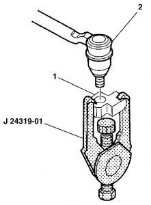
Remove the rack and pinion boot. Important: The rack must be held during removal and installation of the inner tie rod to prevent damage to the rack. Remove the shock dampener (2) from the inner tie rod assembly (5).
Slide the shock dampener (2) back on the rack (1).
Remove the inner tie rod assembly (5) from the rack assembly (1) as follows:
3.1. Place a wrench on flats of rack assembly (3).
3.2. Place another wrench on the flats of the inner tie rod housing (4).
3.3. Rotate the inner tie rod housing (4) counterclockwise until the inner tie rod (5) separates from the rack (1).
Remove the old Loctite(R) from the threads (2) of the rack (1) and the inner tie rod (3).
ASSEMBLY PROCEDURE
Slide the shock dampener (2) forward onto the rack (1).
Important: The rack must be held during removal and installation of the inner tie rod to prevent damage to the rack.
Apply Loctite(R) 262 (or equivalent) to the inner tie rod threads. Important: Threads must be clean prior to Loctite(R) application. Check Loctite(R) (or equivalent container for expiration date. Use only enough Loctite(R) to evenly coat threads.
Attach the inner tie rod (6) on the rack (1) as follows:
3.1. Place a wrench on the flats of the rack assembly (3).
3.2.
Inner tie rod to 100 Nm (74 ft. lbs.). Place a torque wrench (5) on the flats of the inner tie rod housing (4).
Notice: Refer to Fastener Notice in Service Precautions.
Slide the shock dampener (2) over the inner tie rod housing (3) until the front lip of the shock dampener (2) bottoms against the inner tie rod housing (3).
Assemble the rack and pinion boot.
Also, there is a technical service bulletin on the tie rods.
Bulletin No.: 03-02-32-049
Date: October 29, 2003
INFORMATION
Subject:
Release Of New Outer Tie Rod Ends For Service
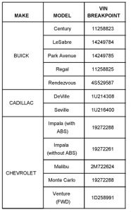
Models:
1997-2001 Buick Century
1997-2001 Buick Regal
2000-2003 Buick LeSabre, Park Avenue
2002-2003 Buick Rendezvous
1997-2003 Cadillac Seville
2000-2003 Cadillac DeVille
1997-2001 Chevrolet Venture (FWD)
1997-2003 Chevrolet Malibu
2000-2001 Chevrolet Impala, Monte Carlo
2002-2004 Chevrolet Venture (AWD)
1997-2001 Oldsmobile Silhouette (FWD)
1998-2001 Oldsmobile Intrigue
1999-2003 Oldsmobile Alero
2001-2003 Oldsmobile Aurora
2002-2004 Oldsmobile Silhouette (AWD)
1997-2001 Pontiac Grand Prix, Montana (FWD), Trans Sport (FWD)
1999-2003 Pontiac Grand Am
2000-2003 Pontiac Bonneville
2001-2003 Pontiac Aztek
2002-2004 Pontiac Montana (AWD)
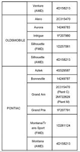
Built Prior to VIN Breakpoint shown.
A new outer tie rod end service kit has been released. When replacing the outer tie rod ends, use the improved tie rod end service kit and modify the knuckles. Follow the service procedure below.
Procedure
Important: DO NOT USE the following outer tie rod end P/N's when servicing the above listed vehicles:
^ 26086579
^ 26086580
1. Raise and support the vehicle.
2. Remove the front tire and wheel assemblies.
5. Using the J 24319-B, remove the outer tie rod assembly (2) from the steering knuckle (1).
6. While removing the outer tie rod end from the inner tie rod assembly, count the number of revolutions it takes to remove the outer tie rod from the inner tie rod and record it. Discard the outer tie rod end.
Important: When sanding the knuckle, DO NOT REMOVE excessive material from the knuckle. ONLY USE the emery cloth supplied in the service kit.
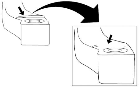
Use the emery cloth supplied in the service kit to remove the sharp edge on the knuckle shown above. The graphic on the left shows the " before sanding" knuckle and the exploded graphic on the right shows the "after sanded" knuckle.
8. Ensure that the sharp edge and the flashing on the knuckle are removed from the outer tie rod end boot/seal area.
9. Install the new outer tie rod end supplied in the service kit by screwing the outer tie rod end onto the inner tie rod end assembly. Turn the outer tie rod end as many turns as it took to remove the old outer tie rod end from the inner tie rod end assembly.
10. Install the prevailing torque nut to the outer tie rod assembly.
Tighten
Tighten the prevailing torque nut to 30 N.m (22 lb ft). Tighten the prevailing torque nut an additional 115 degrees of rotation.
11. "Hand Tighten" the jam nut at this time.
12. Install the tire and wheel assembly.
13. Lower the vehicle.
14. Inspect the front toe and adjust if necessary.
15. Tighten the jam nut against the outer tie rod assembly.
Tighten
Tighten the jam nut to 68 N.m (50 lb ft).
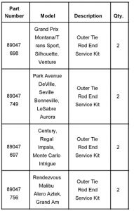
Parts Information
Parts are currently available from GMSPO.
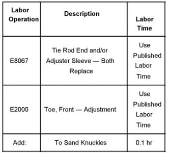
Warranty Information
Oct 10, 2008 at 12:07 AM