Trying to diagnose code P0300, random multiple misfires?

2005 CHEVROLET MONTE CARLO
225,000 MILES • 3.8L • 6 CYL • 2WD • AUTOMATIC
Avatar
SWALDO
  • MEMBER
  • 20 POSTS
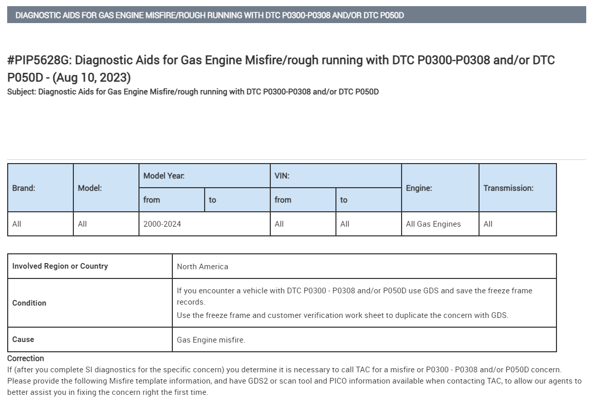
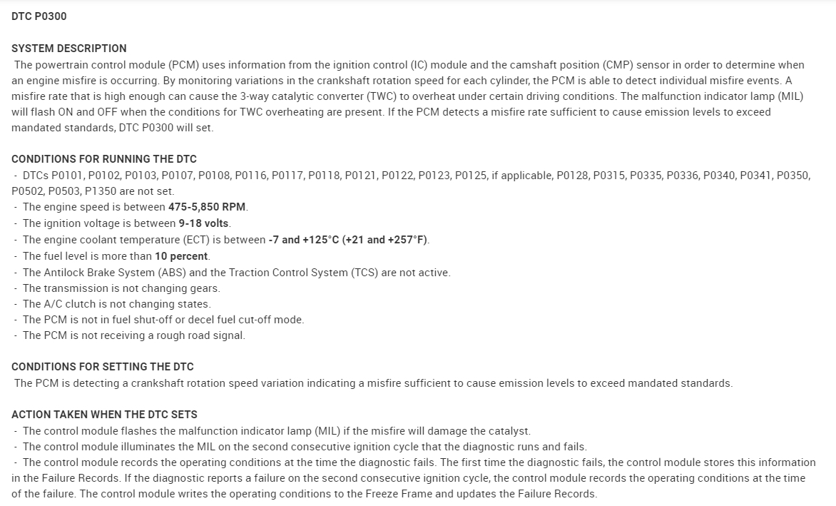
The engine is a 3800 series 2 L3. I’m trying to diagnose code P0300 – random multiple misfires. This behavior began recently.

I can re-create the misfire or avoid it depending on driving style.

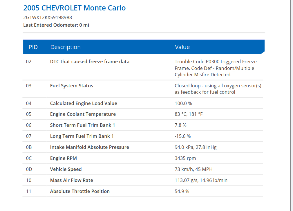
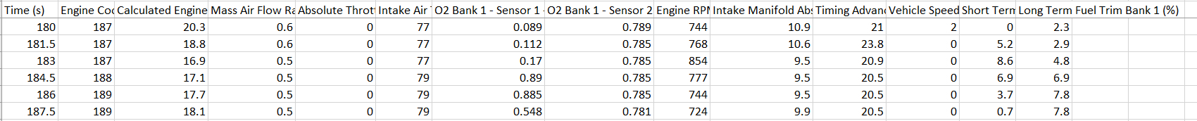
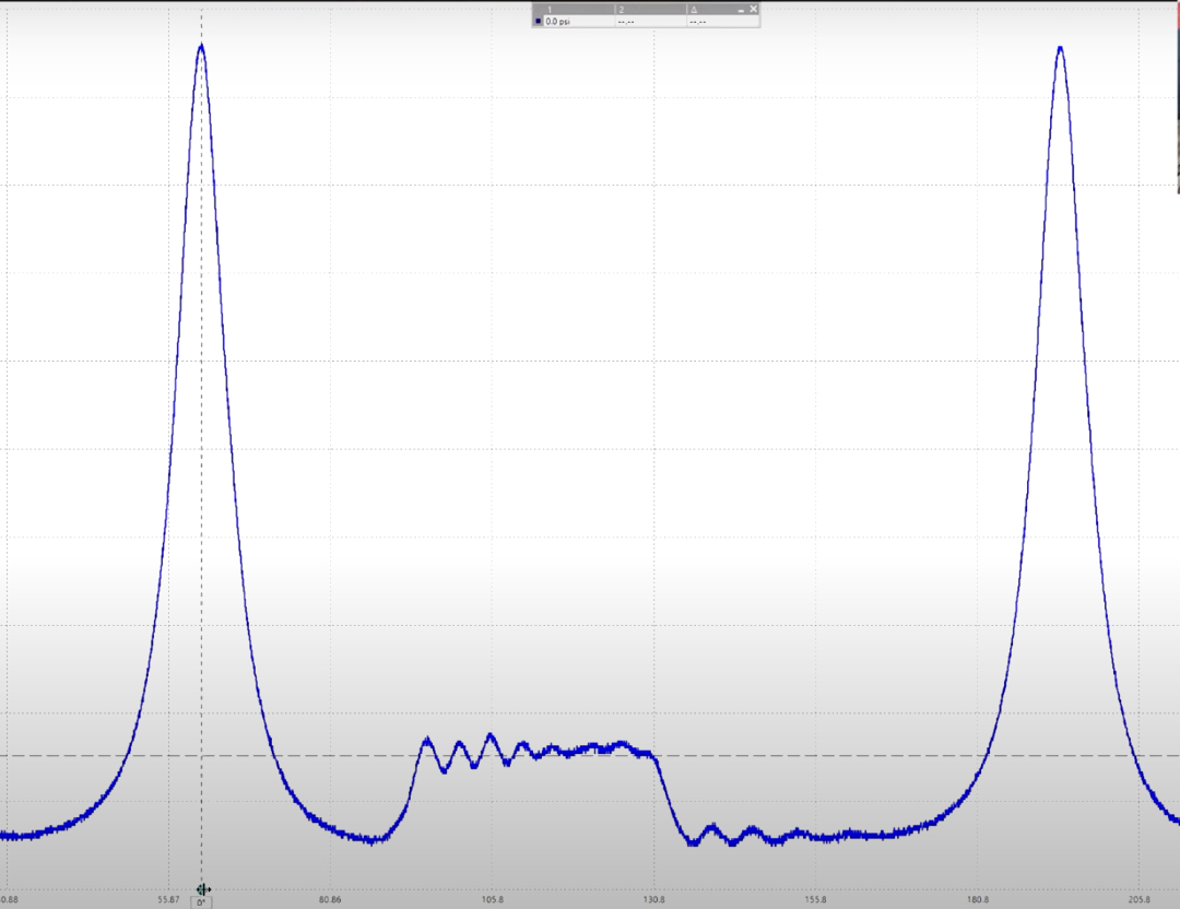
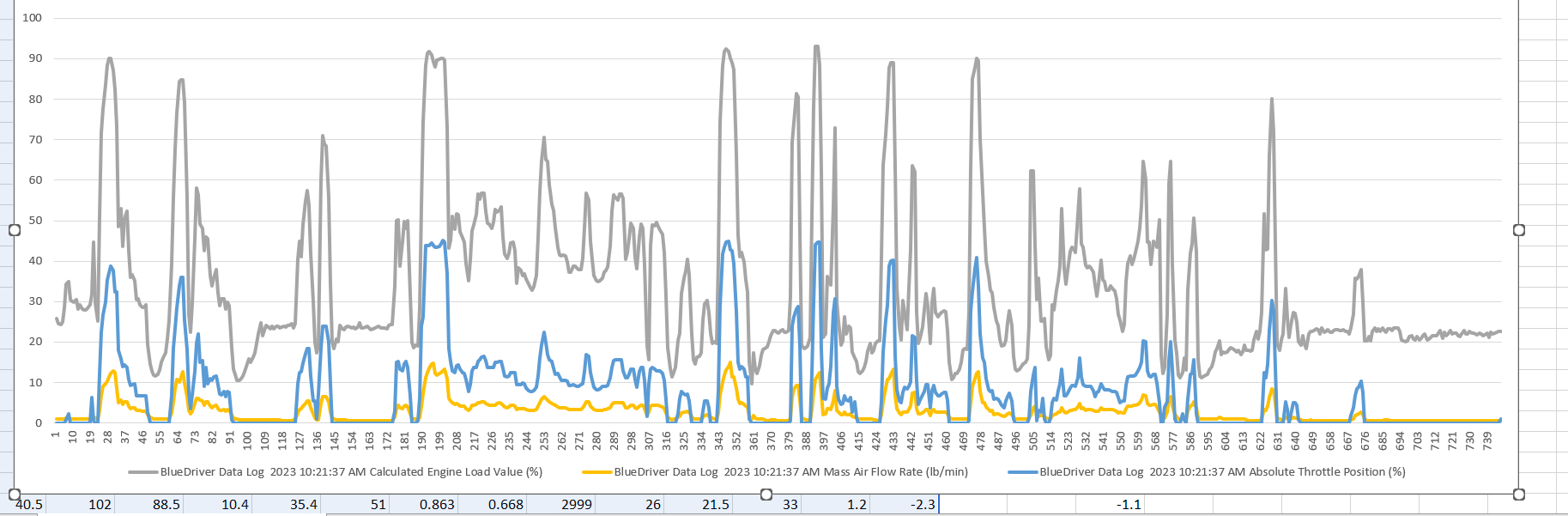
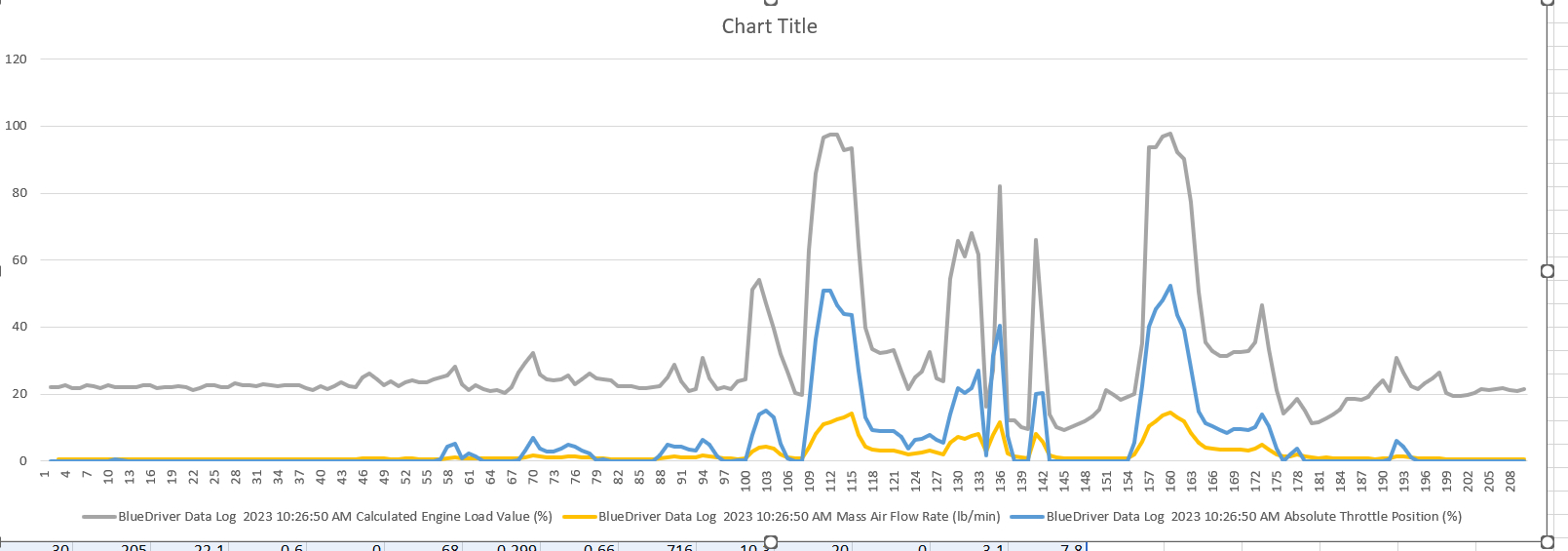
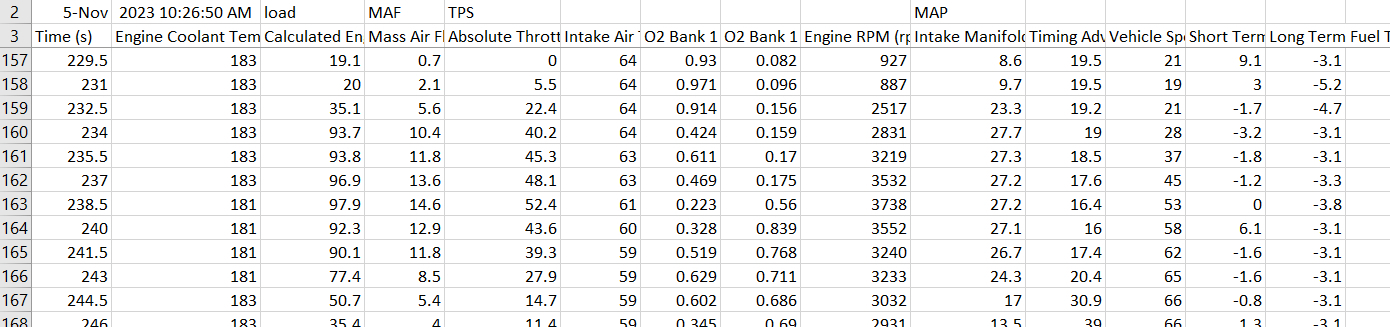
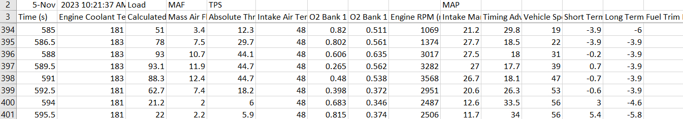
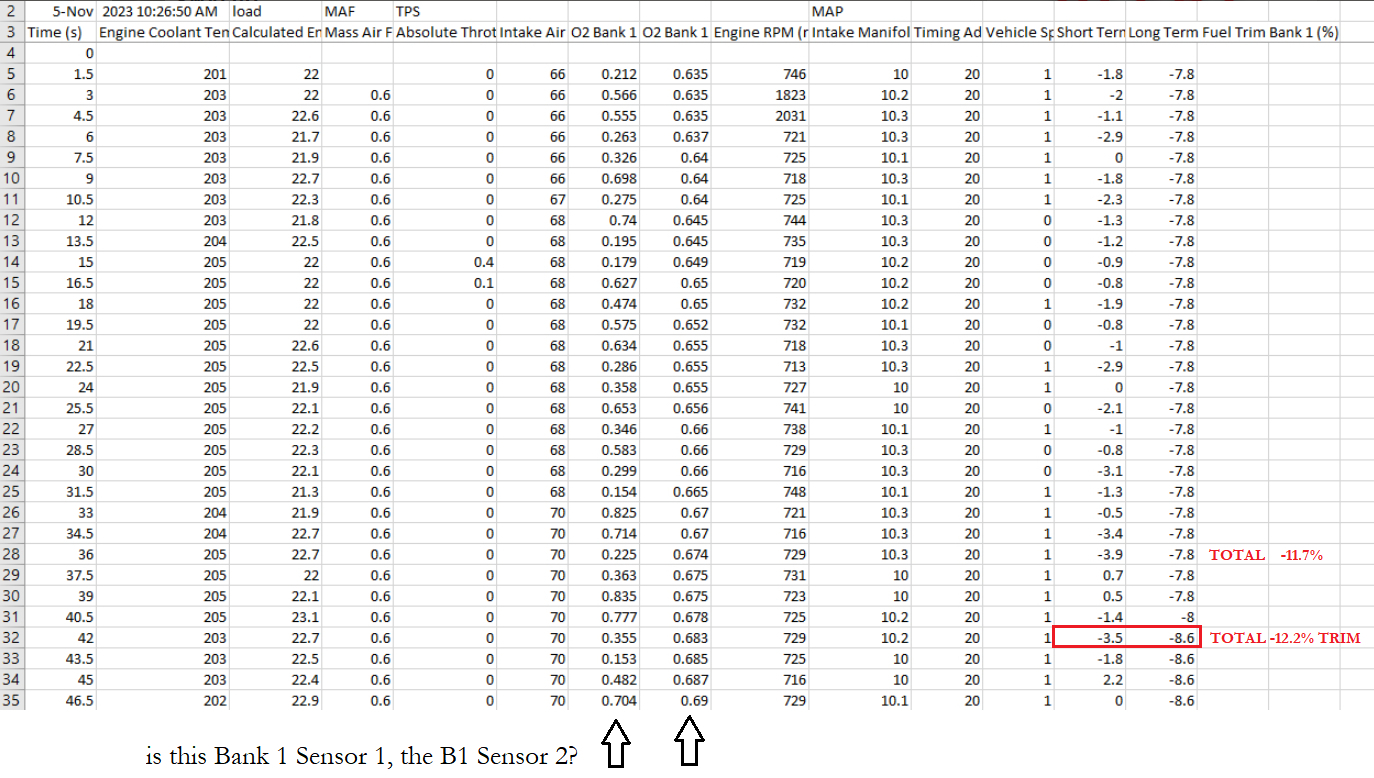
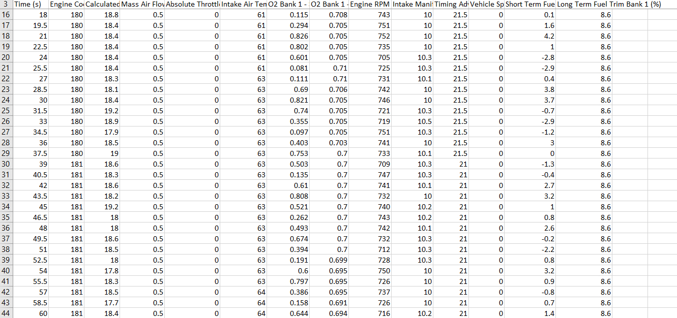
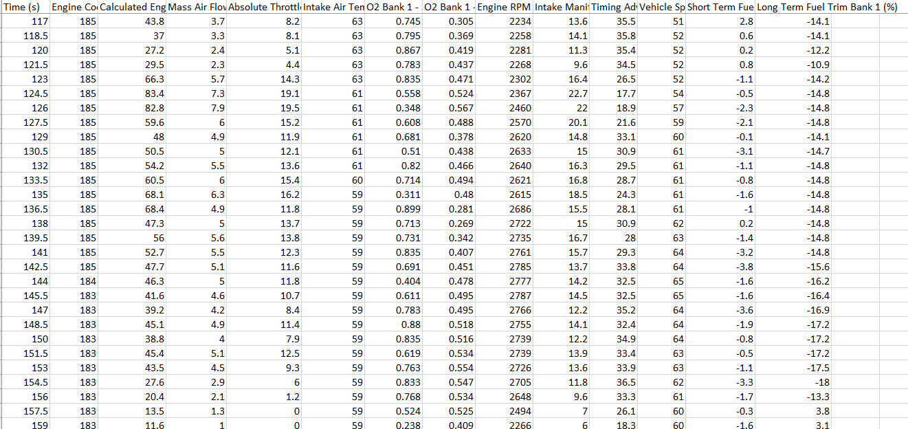
Attached is scan data that is a good representation of the behavior. Numerous scans yield about the same results. The attached data includes some warm idle, and two ~0 to ~60 runs divided by pause/turning around. The first run is semi-spirited driving but not enough to re-create the behavior; the second run is far more spirited, and misfire then occurs, at time 105 seconds. The freeze data of the event is also attached. The engine mal-performs at this point and resumes normal by laying off the gas. The code is always P0300, and never is cylinder specific.

I’m a big fan of using scan data to diagnose the exact problem, rather than throwing parts at the likely candidates. So here are some facts on such candidates:

Newly replaced all 3 ignition coils
Inspected/confirmed all plug wires for continuity
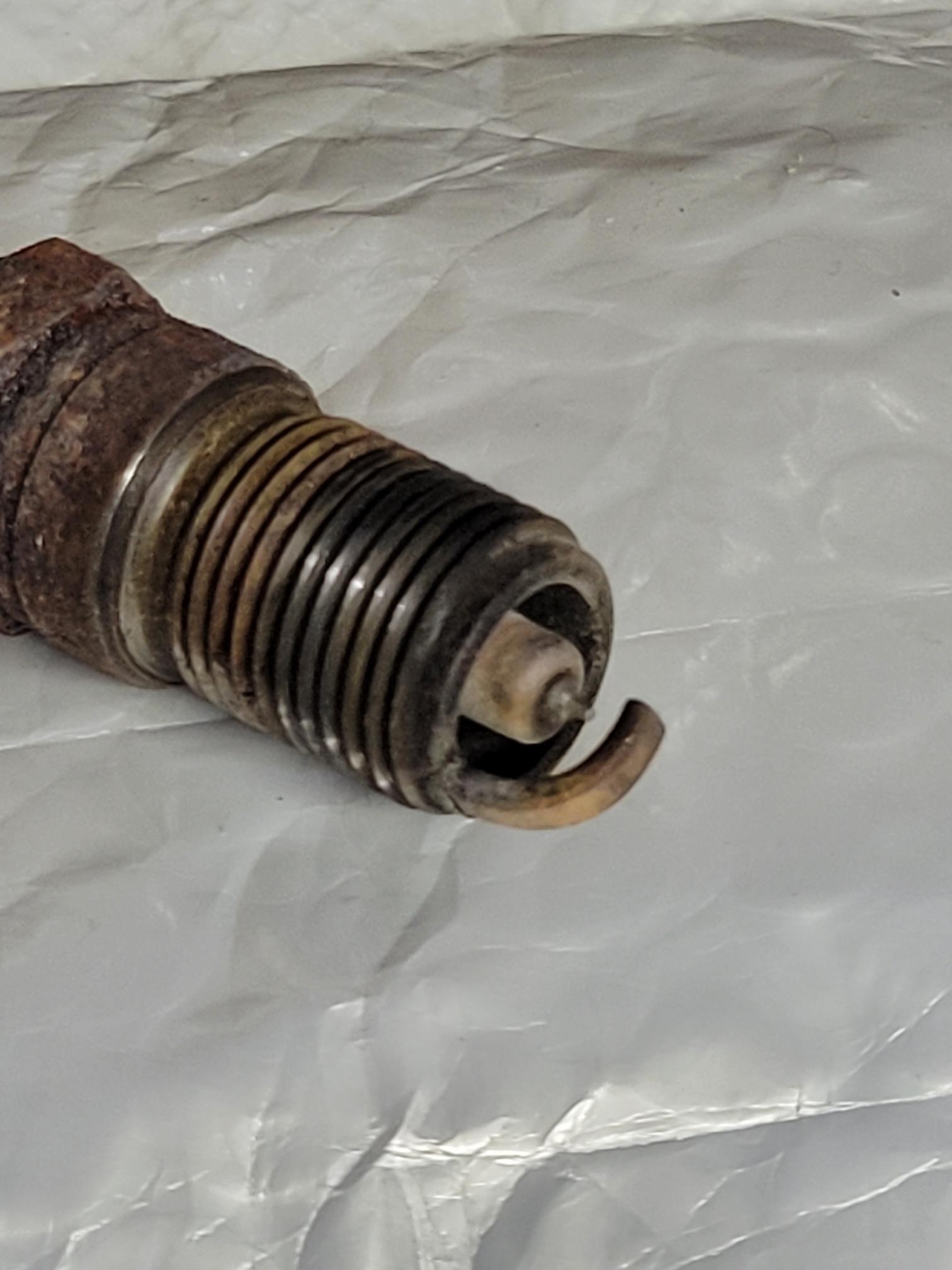
Visually inspected/confirmed spark plugs for normal appearance
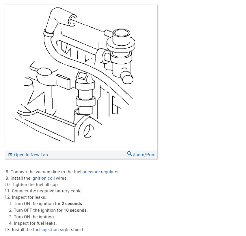
Measured fuel pressure with engine running – 48 PSI, + 8 more PSI when vacuum hose on FPR is disconnected. The pressure is then sustained with the key on, engine off.
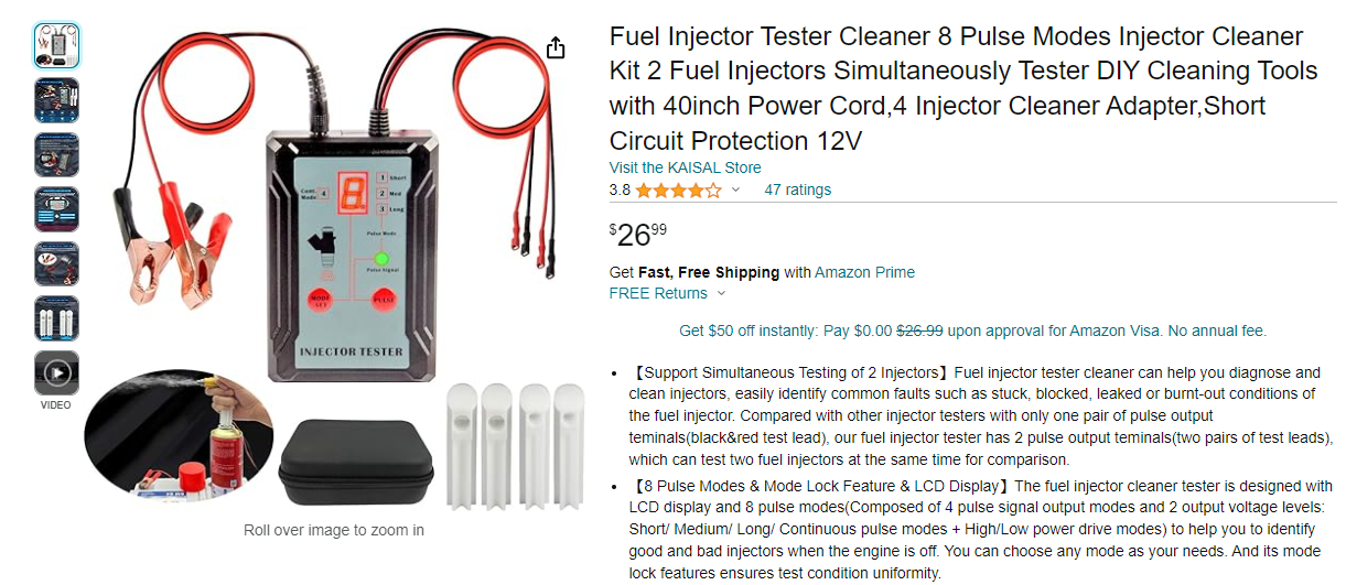
Fuel filter, plugs and wires are all 7 years old, 50,000 miles. Fuel pump is original. Injectors are original. Ignition module is original.
Front O2 is 10 years old, 100,000 miles; rear O2 is 7 years old, 40,000 miles
The EVAP hose from throttle body to EVAP device is capped off and not attached to EVAP device. EVAP has historically had code P0449 due to the canister in the rear, and therefore was disconnected. (I do not reside in an emissions state). Code P0449 does not coincide with the current problem
From the scan data, I’m imagining all sensors are reporting correctly – pending your review

Observations of the data

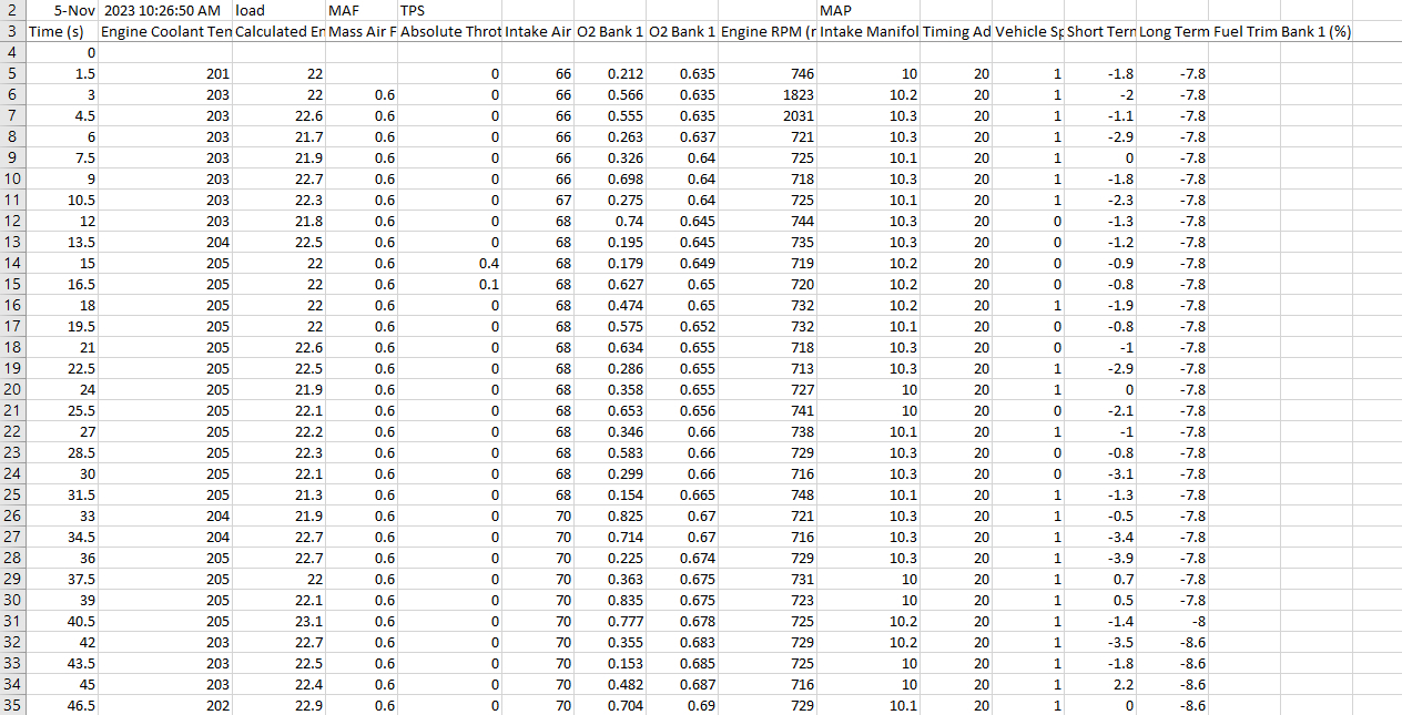
You’ll see the LTFTs are double-digit-negative just about any time the car is moving, beyond the -10 but never reaching -25 that would throw rich code. This suggests correction for a rich condition. Too much fuel or not enough air. I verified the airbox and air filter were not clogged and re-created the misfire with air filter and box removed. Of course, the LTFTs are this way just the same in the first run when no misfire occurs.

The LTFTs then obey the +10/-10 range when idling.

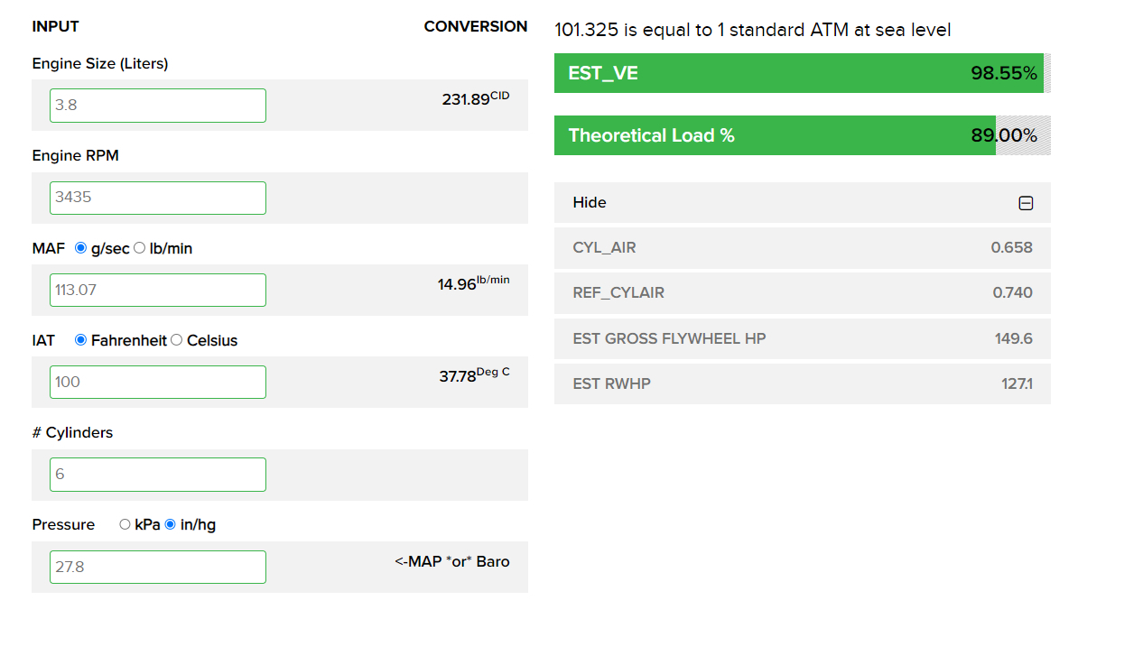
From many observations, it seems that the misfire occurs whenever MAF of 15 to 20 is achieved (MAF beyond 20 has never been achieved) and does not occur at lesser MAFs 13 or below. So, it is not a simple matter of misfiring at a certain RPM.

So, as you might imagine, a precise diagnosis eludes me. Perhaps an expert 2nd opinion will be revealing.

Thank you
Oct 16, 2023 at 8:18 AM
Advertisement
Avatar
SWALDO
  • MEMBER
  • 20 POSTS
I can't add the all-important scan data and freeze data to this form. I'll attach these to email when someone emails me. thanks
Oct 16, 2023 at 8:25 AM
Avatar
AL514
  • CERTIFIED EXPERT
  • 5,465 POSTS
Hello, we don't communicate through email, it's just here, posting back and forth. When you say the MAF is reading 15 to 20, are you referring to 15grams per second (g/s) and are the front oxygen sensors fluctuating between 0.2v and 0.8v at a relative fast frequency, meaning neither of them are hanging up in the 0.8v (800mv) range? If one of them is stuck at a rich indicating voltage level, the PCM will start to reduce the fuel from the mixture and fuel trims will go negative when they shouldn't. Basically, tricking the PCM into thinking the mixture is rich when it is not.
I agree on finding the issue as well instead of throwing parts at it, that is not the correct way to diagnose an issue.
And if you can post the freezeframe data here it would be good.
And does this vehicle have a super charger?
Oct 16, 2023 at 9:04 AM
Advertisement
Avatar
SWALDO
  • MEMBER
  • 20 POSTS
Hello,

My MAF figures are in LBs/min. The front O2 is frequently switching and not hung up in the .8V range. There is no SC.

My scan data is a CSV file and the freeze data is a PDF. Each results in 'file type not allowed'. How can I get these to you?
Oct 16, 2023 at 9:35 AM
Avatar
SWALDO
  • MEMBER
  • 20 POSTS
Freeze data attached.
Oct 16, 2023 at 9:42 AM
Avatar
AL514
  • CERTIFIED EXPERT
  • 5,465 POSTS
Your short term is correcting there somewhat at a higher rpm, Total fuel trim when the code set (-15,6 - 7.8= -7.8) so -7.8 total is not that bad, I put these numbers into a VE calculator which Ill post below, so it's a Volumetric Efficiency test that shows how well the engine is breathing, so if you had a catalytic converter that was restricted it would show up here.
And according to the test everything looks good. What are your fuel trims doing at idle? And does the MAF read around 4 g/s (or 0.53 lb/min)?

On this freezeframe data you're at 100% calculated load, with about half throttle, 54% so I assume this is a cruising speed type of run. I would be interested in knowing what the Long term and Short term are at idle. ECT looks a little low here, and the -15% is being corrected for but something is causing it to initially drop down that low, I think with seeing these numbers (and you are correct, the sensors look to be giving correct data)

I would do a fuel injector balance test. It might be that they are not all flowing the same amount, hence the -15%. but then at higher rpm since the engine is using more fuel at that time, the short term starts to correct, because the engine would now be able to use any extra fuel.

Do you own a fuel injector pulse tool? With doing a fuel injector balance test, you'll have a fuel pressure gauge on the rail, and prime the fuel system with key On, and then pulse the injector, write down how much pressure drops from your 48psi, then move on to the next injector, re-prime the fuel system up to 48psi again, and repeat. each injector should be within 1-2psi drop of each other. Once you have done all 6, start the vehicle and let it run for a few minutes to get the fuel out of the cylinders. And run the test again,

I will usually check the injectors like this twice to see if the numbers all stay the same. Some injectors will act up at higher temperatures. So, you could test while cold, go for a ride and retest to see if anything changes. Because besides the ETC looking at little low, which you may want to see if it gets up to around 205f range, at a hot idle. Everything else looks good. A low engine coolant temp sensor will enrich a mixture, you would have positive fuel trims though.
The calculated load looks a little high as well, but that can be scan tool data. I would also check at key On engine Off, that your TPS goes higher at WOT. 54% looks low for that rpm, but it's also measuring absolute throttle position, so I'm not 100% sure what else that takes into account, Ill look through some service info on that, but try the injector balance test, make sure they are all flowing equally. If so, then next you would be on to some possible compression issue. Sorry for the long post, I'm just looking at what you posted and your data at the same time here. If you have any questions on doing the injector balance test, I can find a video for you.

Oct 16, 2023 at 10:51 AM
Avatar
AL514
  • CERTIFIED EXPERT
  • 5,465 POSTS
Here are some extra Technical Service bulletins for cylinder misfire codes setting.
Oct 16, 2023 at 11:15 AM
Avatar
SWALDO
  • MEMBER
  • 20 POSTS
Here is a snapshot of a couple frames of idle to answer your idle question. The TPS does indeed range to 100% when pressing pedal to floor with the key on, engine off. So, I'm looking at the injector pulse test. I do not already have such a device. Thank you
Oct 16, 2023 at 11:36 AM
Avatar
AL514
  • CERTIFIED EXPERT
  • 5,465 POSTS
It's a really great tool to have, even the cheaper $30 unit works just fine, it has 3 different settings, where it will pulse an injector for 50ms at 2.5ms pulses if I remember correctly. It's really the only way to measure injector flow, besides buying one of those thousand dollar injector flow bench testing units. It's even good for checking new injectors, because sometimes aftermarket fuel injectors will flow differently than the OEM ones on the vehicle now, which will through off fuel trims as well.
I'm not sure if you have used an oscilloscope before, but you can do a relative compression test with a scope. This is a relative compression test I did on a 4-cylinder Honda CRV, this is the starter motor current flow, but you can see where one cylinder here has a little bit lower compression hump, The next one after it is a little low as well. This was taken with a Pico scope and amp clamp on the main battery cable. Very effective test to check engine mechanical really quick when dealing with cylinder misfires.
Oct 16, 2023 at 12:06 PM
Avatar
SWALDO
  • MEMBER
  • 20 POSTS
What would the VE look like if the exhaust was restricted? thanks
Oct 16, 2023 at 12:53 PM
Avatar
AL514
  • CERTIFIED EXPERT
  • 5,465 POSTS
This is one of the VE calculators you can use, it's best to do a wide-open throttle run and record the data while doing it and use those numbers to input in. And with either a restricted exhaust, or extreme air intake issue, even a valve adjustment issue, the EST_VE section will be low, (estimated volumetric efficiency) a restricted cat can reduce the VE to 50% or even lower to where it ends up being a no start. On the website there is a button up top that reads "Show VE Calculator Instructions". It shows the best conditions and ways to get the most accurate results. If you ever suspect a restricted exhaust, I will pull out one of the front oxygen sensors and do a back pressure test with the sensor out. Just starting the vehicle for a couple minutes and see how much pressure there is will tell you if the cat has melted down the substrate and blocked off the exhaust, exhaust back pressure max reading should not be over 1.5-2psi, which is barely anything. I'll also check the condition of a cat using a borescope camera and looking at it through the front oxygen sensor opening. I take pictures sometimes to add to a customer's post repair order so they can see for themselves that it's in good condition.
Another method is to use a pressure transducer and go in-cylinder and take a look at the waveform, cranking and then running. This waveform below is an in-cylinder waveform, you can see the compression stroke, the exhaust stroke where it plateaued, and then the next compression tower. A restricted exhaust would have higher pressure above the zero line in the middle.

https://atgtraining.com/atg-volumetric-efficiency-calculator/
Oct 16, 2023 at 3:20 PM
Avatar
SWALDO
  • MEMBER
  • 20 POSTS
Okay. Thanks for the VE explanation. I see what you're saying there. I will do the injector test near future.

I do indeed have a non-automotive brand inexpensive laptop USB oscilloscope. I find the scope compression test you show interesting, as I'm only familiar with the per-cylinder physical gauge compression test. Is it just as effective to scope the volts at positive battery terminal while cranking? (As I'm lacking an amp clamp)

Thank you
Oct 17, 2023 at 5:21 AM
Avatar
AL514
  • CERTIFIED EXPERT
  • 5,465 POSTS
Yes, you can do battery voltage instead of cranking amps, you just need to invert the waveform, because it will be the opposite of the amperage waveform. So, flip it upside down when on the battery terminals, it's a great fast way to see if there is a mechanical issue vs fuel or ignition when dealing with a misfire. You're really just seeing the crankshaft's speed on compression strokes. So, if you happen to get a hump in the waveform that is low on compression and then the next hump may appear a little bit higher sometimes because the crankshaft is speeding back up at that point. So, it's not necessarily another bad cylinder after the low compression one. If you have 2 channels on your scope, you can also use the other channel to grab a sync, such as a fuel injector firing or coil firing so you know where the effected cylinder is through the firing order. YouTube has some good videos if you search for "scope Relative compression test", it will go into some more detail, but just by your question about the using the battery instead, I can see you have a good grasp on things. Most of the time I have to explain to people how to take a voltage reading with a multimeter. Which takes a long time, but I like the VE test because you can put in some data numbers from a WOT run and see how well the engine is breathing without having to tap into the exhaust for back pressure testing right away. I would do that after to verify a bad cat if needed.
Oct 17, 2023 at 9:25 AM
Avatar
SWALDO
  • MEMBER
  • 20 POSTS
I'll first perform the injector balance test near future and provide results.
Oct 18, 2023 at 5:26 AM
Avatar
AL514
  • CERTIFIED EXPERT
  • 5,465 POSTS
Okay, whatever you think is the easiest route to take, I'll do some of these tests just to keep them fresh in my mind as well. Once you run through the fuel injector balance test, you'll really get a sense of the results and see even the slight differences between injector flow. I'm adding this video on the relative compression test at the battery posts because I forgot to add the section about AC coupling the signal when grapping a capture at the battery. He also goes over using a high amperage clamp and low amp clamp as well. If you scope has BNC connections, you can get a Hantek high amp clamp for pretty cheap, I have one and still use it, it takes a 9volt battery, but has large enough jaws to go around the thicker battery cable, with an amp clamp you can use either the negative or positive lead when watching starter current. But check this video out, it will help with getting your settings correct for voltage levels. It's not very high when only measuring voltage vs the amp clamp which will be monitoring a few hundred amps on a starter draw.
Let me know how you make out with the injector test, I'm always interested in test results.


https://www.youtube.com/watch?v=Sg7HfvQsHG8
Oct 18, 2023 at 10:03 AM
Avatar
SWALDO
  • MEMBER
  • 20 POSTS
I believe the injector balance test revealed something significant.

Performing the mode 3 low power test (100 pulses @ 3.5 ms pulse width), I have 4 injectors that all dropped 19-20 psi; 1 injector that dropped 18 psi; and 1 injector that was 23-24 psi (Cylinder #1). I performed the test 5 or so times on each injector to get good data (at a constant engine temp). Cylinder #1 is definitely beyond 10% from the others. The fact that cylinder #1 injects more might explain the negative double digit LTFTs whenever the car is moving. And the misfire only at higher load.

I also noticed that as engine temperature changes, so does the psi drop; it appears a warmer engine has a lesser psi drop across all cylinders. Very interesting. Even so, cylinder #1 always dropped 4 psi more than the others regardless of temp.

It was also a case whereby performing mode 1 low power test (single pulse of 255 ms) all 6 injectors behaved the same. Cylinder #1 did not show itself to be abnormal. If this was the only test performed, I would’ve concluded "all good".

So now I’m thinking what is the conventional approach in this case? How would it be handled with a customer at a shop?
All injectors are original, that’s 18 yrs and 225K miles. Perhaps it is prudent to replace all 6. I've also heard ‘never need replaced, just clean them. I've also heard just clean or replace the bad one. Of course, I only want to do the work one time, removing fuel rail etc.

In the case of replacement, I’ve also heard the "less expensive ones are all junk"; and I’ve heard the OEMs are ‘unnecessarily expensive.

So, assuming you agree with the diagnosis, how to proceed?

Thanks
Oct 23, 2023 at 5:33 AM
Avatar
AL514
  • CERTIFIED EXPERT
  • 5,465 POSTS
Okay, glad you got some results from those tests, did you hopefully start the vehicle in between testing so as not to flood out the catalytic converter with fuel. It should be started in between each set of tests.
But yes, injectors will definitely act differently at varying temperatures. When they are hot they expand like everything else, that can cause them to stop working fully sometimes, but really anything can happen. You're correct, It will cause the fuel trims to go negative because that cylinder is running rich. and depending on if the injectors are Bank fired or sequential, the ECM will reduce fuel to that entire side of the engine if they are bank fired all together. I always like to see what the difference is when it comes to flow rates. It is best to replace them all at once. because many fuel injectors can be at different flow rates, especially after market ones. They all need to be flowing the same, be the same manufacturer, and OEM is the best. They might cost more, but if you have to go back and end up replacing them all again because misfires codes don't go away, it will cost more in the long run anyway. And you shouldn't have to replace them again in the life of the vehicle, unless one comes with a factory defect.
Of course, replace all the seals as well, there's a top and lower one. I'll see if there are injector seats for this vehicle. I don't know off hand if GM has injector seats in the intake manifold. Ford does, they just sit in the intake manifold and the injector sits in that. Here's a guide to help. and if there's anything in service info on seats ill post it as well as any other important info.

Also do an oil change after the repair, I'm sure the oil in contaminated with fuel by now.
Ok they are very specific when ordering new injectors for this vehicle. Below is the service info.
I recommend taking pictures as well before taking everything apart, so you have a reference to where everything goes after and be really easy on the wiring connectors to each injector, they are high mileage and have been sitting like that for a long time, so the wiring will be brittle.

https://www.2carpros.com/articles/how-to-replace-a-fuel-injector
Oct 23, 2023 at 10:11 AM
Avatar
SWALDO
  • MEMBER
  • 20 POSTS
Thanks for the info. I'll change them and let you know.

I did indeed start the car after each and every injector test.
Oct 24, 2023 at 8:38 AM
Avatar
AL514
  • CERTIFIED EXPERT
  • 5,465 POSTS
Okay, sounds good. Just curious, what is the max voltage level for your scope? And does it have BNC connectors for each channel? If you have 20:1 attenuators, you can capture some injector voltage waveforms that can show a lot too. Even watching ignition coil primary or secondary voltage waveforms can show if a cylinder is running lean or rich by the height of the voltage spike. This is the waveform I took from my own vehicle, it's the ignition coils current ramps, I know you don't have an amp clamp, but just showing some examples, you can see that first coil ramp has a downward spike at the end, that's indicative of a secondary ignition problem with the plug or plug wire.
The 2nd waveform is an injector voltage waveform, where you can see the pintle hump. But you need an attenuator on the scope due to the high voltage that coils and injectors spike to. Coils can fire up to 400 volts on the primary side. So, without an attenuator it will fry the scope. I just wanted to show some of this info because we rarely get people who use scopes.
Oct 24, 2023 at 9:21 AM
Avatar
SWALDO
  • MEMBER
  • 20 POSTS
It is +/- 5 volts, and the probes have a 10X switch on them. It does indeed have BNC connectors. I see how I could attach an inexpensive 20:1 attenuator, along with probe on 10X, and therefore be protected for both interesting tests you show. I also looked up the amp clamp and generally a number of things to make the scope more versatile, nothing too expensive there. Thanks

On one occasion I measured RPM of a lawn mower by attaching probe (set on 10x) to ignition coil ground wire, with a 2200 ohm resistor in series just in case and got my wave form. So, I have innovated on this topic, but getting the right thing is far better.

So is it the case whereby a richer cylinder would have the higher voltage spike, or the lower?
Oct 24, 2023 at 10:42 AM
Avatar
STRAILER
  • CERTIFIED EXPERT
  • 53,854 POSTS
If I could jump in here, when the sensing wire inside the MAF sensor gets worn out it will cause this problem. I would replace it with an AC delco unit. Cleaning it will not help.
Oct 24, 2023 at 10:44 AM
Avatar
SWALDO
  • MEMBER
  • 20 POSTS
injector change still pending - slight delay.
Oct 30, 2023 at 7:43 AM
Avatar
AL514
  • CERTIFIED EXPERT
  • 5,465 POSTS
You can try changing out the MAF like Ken said as well. Even try unplugging it and see if it runs on a default strategy for the MAF data. Some manufacturers do that, if it just stalls out then the ECM doesn't have a default setting for the MAF. I see in the wiring diagrams there is a MAP sensor as well. So it might run with the MAF unplugged.
Oct 30, 2023 at 12:29 PM
Avatar
SWALDO
  • MEMBER
  • 20 POSTS
Hello gentlemen, here is update:

The injector change was completed. I used new OEM injectors from Standard Motor Parts.
This did not resolve the misfire condition at high load, nor did it change the ‘double digit negative LTFTs whenever the car is moving’. In fact, they got a little lower, to the point of -19, which I hadn’t seen before anything less that -15.

Then the MAF sensor was changed with new OEM sensor Delphi brand.
This indeed made the double digit negative LTFTs vanish, and now the figures are ‘normal’. This did not resolve the misfire condition though.

On close examination of previous data, it appeared the old MAF would jump a little higher once in a while versus frames right before and after. On these frames, I would get a VE of 110% or 115% and concluded eventually that maybe isn’t right. The highest MAFs I’d see would be 18 or 19, and %calcload would be 100%. Now my highest MAF is 16 and %calcload never exceeds 98. I’m still not flooring the gas. Now any VE at higher loads is 85% to 94%. So, I believe the new MAF is more accurate and the old MAF was resulting in the negative double digit LTFTs. The old MAF was always correct at idle though and seemed correct at part throttle.

It continues to be a very fine point by which I can recreate the misfire or avoid. I did lengthy testing after these changes and found that by keeping TPS just below 50, %calcload would max at 93%, and misfire is avoided. If I TPS to just above 50, %calcload would get 97% or 98% and misfire would occur. See the two graphs; the more lengthy graph displays multiple events where %calcload reaches above 90%, MAF is 14 or 15, and misfire does not occur. There are no misfires in this lengthy drive. In the second shorter graph, I have recreated the misfire at both notable peaks with just a bit more TPS above 50, and %calcload up at 97 or 98.

It is quite a mystery what condition would occur so specifically to cause misfire in this way, without it happening otherwise.

I then performed RC test, battery voltage style, non-inverted, so of course the troughs are the compression strokes. See the two consecutive scope frames. It appears my non-automotive scope leaves a bit of a gap between frames, as well as being a bit messy on this test. It tells me I’m good on compression though. Feel free to examine.

Various higher load VEs tell me (according to the ATG instructions) I’m reasonably good on compression, and reasonably good on airflow. In fact, I’m running out of things it could be. Is it possible the CAT is clogged in some slight way, that only causes difficulty at highest loads? I plan on doing the CAT backpressure test upon getting a fitting, but this test might not reveal imperfections at higher load, or would it? Maybe the CAT is just fine as well.

Maybe with these changes, an ‘ECM reset’ by disconnecting the battery for a while is applicable? – don’t know.

Let me know what you think. Of course, if you need full scan data, I can provide full CSV files.
Nov 6, 2023 at 7:12 AM
Avatar
STRAILER
  • CERTIFIED EXPERT
  • 53,854 POSTS
These readings are telling us you may have an intake valve leaking which will affect the other cylinders. Here is a guide to help run the test. Also, while the spark plugs are out check the condition and replace if needed.

https://www.2carpros.com/articles/how-to-test-engine-compression

Please go over this guide and get back to us.
Nov 6, 2023 at 8:37 AM
Avatar
SWALDO
  • MEMBER
  • 20 POSTS
Sure, can proceed with physical compression test. What readings are you seeing exactly that suggests that. The RC graphs, or the symptoms?
Nov 6, 2023 at 9:46 AM
Avatar
AL514
  • CERTIFIED EXPERT
  • 5,465 POSTS
That is because of the low sampling rate, but the some of the humps do look a bit higher than others. It could also be a valve that is sticking at some points or just not sealing all the way, and like Ken said it will affect all cylinders because the compression pressure is being pushed back into the intake manifold on the compression stroke, when the intake valve is actually supposed to be closed. You can do a cylinder leakage test with the piston at top dead center, then put some compressed air into the cylinder and listen for it leaking into the intake manifold, you might hear it popping into the intake as well. But the calculated load is very high for light throttle cruising. Just looking at the Calculated load, where it's near 98% and the MAF is only at roughly 15lb/m your RPM would need to be around 3,200 RPMs for that to happen. But you're only at about 50% throttle. But do the back pressure test as well since you've got the tooling coming.
It looks like you have a MAP sensor as well, you could scope that signal, and if compression pressures are being pushed into the intake manifold you would see spikes in the MAP signal, it's only a 0 to 5volt signal, but that be good to watch for valve sealing issues. The MAP should be pretty steady as the throttle opens and closes, so if you see spikes in the signal, they shouldn't be there, at idle (high manifold vacuum) you should have low MAP voltage, and wide-open throttle (where manifold vacuum is low, positive pressure is rising) is should be higher towards 5v. Since the vehicle has one though, it's worth seeing if there are any pressure spikes coming from an intake valve not sealing.
Nov 6, 2023 at 1:40 PM
Avatar
SWALDO
  • MEMBER
  • 20 POSTS
You guessed the RPM pretty close, but since you are remarking something isn't quite right amongst the MAF, load, RPM and TPS, here is the full frames image at that misfire event (about row 163), and another image during which no misfire occurs. If there is something about MAF, load, RPM and TPS that doesn't add up that would be interesting. Although the TPS is around 50, plus or minus in all cases, I'm going through 1st and 2nd and accelerating rapidly when I intentionally recreate the misfire or come close but avoid, and MAP is always up there around 27" Hg. I suppose it's relative though, but it doesn't have a feel of light throttle cruising. At light throttle cruising (3rd or overdrive, highway etc.,) there is no malfunction.

If you're seeing some higher humps in the RC test, (I kind of see it in one image) tell me how it indicates intake valve as more likely than exhaust valve or rings. I'm curious there. In any case I'll proceed with the tests. Thanks both.
Nov 7, 2023 at 5:50 AM
Avatar
AL514
  • CERTIFIED EXPERT
  • 5,465 POSTS
I just mentioned the MAP because you can scope that signal and use it to tell if there are positive pressure spikes due to an intake valve issue. Your coolant temperature is low the entire time during that data. What's your long term and short-term fuel trim at idle? Warmed up but close throttle. Just looking through your live data here.
Nov 7, 2023 at 1:34 PM
Avatar
SWALDO
  • MEMBER
  • 20 POSTS
Here you go: Attached is scan data at idle (vehicle speed of 1 while in car wash). I suppose looking at a lot of my data, temp climbs to 205 only during idling, but is around mid 180's or so whenever moving. Let me know if that indicates anything.

Also attached, I performed the MAP scope while cranking for a good 5 or 6 seconds, including key on before and after, as you described and after further reading on the subject. I'm not sure if test is best performed while cranking, driving or idling. Let me know. Of course, the per cylinder intake strokes are well depicted here. Let me know your interpretation. Still planning on the other tests.
Nov 8, 2023 at 5:41 AM
Avatar
SWALDO
  • MEMBER
  • 20 POSTS
Perhaps the same can be done for exhaust strokes? some sort of probe into O2 port. Perhaps there is one to detect crankcase blowby, some sort of probe into the dipstick? thanks
Nov 8, 2023 at 5:56 AM
Avatar
AL514
  • CERTIFIED EXPERT
  • 5,465 POSTS
Well, I was thinking more of using the MAP to see any intake pulses that should not be there. Another test you can do for valve sealing issues is a good ole vacuum gauge on the intake manifold. If it jumps around, that's a sign of a cylinder not sealing correctly. I've had this vacuum gauge chart forever; I should have thought of this to begin with. You can see on the chart that any valve issues will cause the needle to bounce all over the place. Your scope has a pretty low sampling rate, so it's inconclusive. There is a lot of noise in that signal, those downward spikes almost look like an ignition coil or wire strike. But the fuel trims look like the engine is rich at idle, with the negative numbers and then they come up closer to 0 at higher RPMs. But try the vacuum gauge on the intake manifold and see if it's steady or bounces around. The only issue is if you can duplicate the problem while testing. Checking for crankcase pressure will tell you if the rings are sealing correctly.
If you think it's a burnt exhaust valve then I would do a cylinder leak down test with compressed air into the cylinder, I have even seen a smoke machine used to determine a burnt exhaust valve.
But it seems like you're dealing with more of an intermittent problem. Since you mention its only at certain throttle position and engine load. Put a vacuum gauge on the intake manifold, somewhere you can see it from the driver's seat. And put the car in gear, and do a little brake torque, see if that causes a valve sealing issue to show itself.
And if you catch a bouncing needle at all, then do a leak down test.
And you're sure about the plugs and wires? I know you replaced the 3 coils, and the MAF so far plus injectors. So, we're down here to only a couple things here. How do the plugs look, and the plug gaps or electrode wear. Your fuel trims increased after the injector changed out because now you have injectors that are all flowing the correct amount.
Here's the entire flow chart for a P0300 code setting (pg 3-7). So you can go through that, I know you mentioned doing a back pressure test when the tools came, so check that at idle to just to cover your bases.
Nov 8, 2023 at 12:59 PM
Avatar
SWALDO
  • MEMBER
  • 20 POSTS
Answers to your questions first:

Yes, it is Bank 1 sensor 1, and Bank 1 sensor 2, as you labelled it. Apparently, there is no other bank.

The irony regarding the LTFTs is prior to injectors/MAF change, LTFTs at idle were always normal, and double-digit-negative whenever car is moving. Now it is the opposite, somewhat negative at idle and normal when part throttle or higher throttle.

I had checked existing wires for proper continuity and resistance, and visually inspected all plugs and found them all good. All with 50,000 miles on them. I’m going to change the plugs anyway while doing compression testing.

I plan on performing the in-cylinder pressure transducer test on all cylinders, cranking and running, as you had referenced earlier in our conversation. It appears from further reading that a conventional peak compression gauge will not necessarily reveal all. A Hantek automotive scope will be used as well. My current device only does 240K sa/s. In fact the waveforms I already got will be done over with the better scope.

And proceeding with the other tests including the vacuum test per your chart. It might take a bit of doing; I’ll let you know. Thanks
Nov 9, 2023 at 6:33 AM
Avatar
AL514
  • CERTIFIED EXPERT
  • 5,465 POSTS
How negative are the fuel trims at idle now? In-cylinder waveforms with a pressure transducer is a very effective testing method, although they do take a while to understand what you are seeing. I use a Pico scope for that type of testing because it has measurement rulers you can move from the first compression tower to the next 0 to 360 degrees, Ill post an example of that just to show you, but also have a small handheld 2 channel Hantek scope which has a multimeter and signal generator. I use that thing probably the most since I don't need a laptop to use it like a Pico requires. But the vacuum gauge with a bouncing needle will tell you right away if there is a cylinder sealing issue. I'm surprised there isn't a 02 sensor on bank 2, at least a front one, but you're right, looking at the wiring diagrams there is only 1 front and 1 post cat 02s. The 02 sensor 2 (rear) has a pretty steady voltage which is good, if the cat was allowing emissions gases passed it, the rear 02 would be fluctuating just about the same frequency as the front 02. So, it doesn't look like a converter issue, besides you would have a lack of power all the time if this was a restricted exhaust.
Nov 11, 2023 at 1:17 PM
Avatar
SWALDO
  • MEMBER
  • 20 POSTS
The last image I gave you (that you then notated items in red) is indeed my current FTs at idle after injectors/MAF change. Just to illustrate, here is a previous image of idling before the injectors/MAF change. Then a second image of negative LTFT's while moving part throttle, prior to injector/MAF change. Now since injector/MAF change, the negative LTFTs while moving are no longer occurring, but they are negative at idle as you noticed. Car idles great either way. Car drives great either way until that TPS and load threshold is achieved.

I performed the Cat backpressure test and it passed. Pressure was about 1 PSI at 3,000 RPMs.

I performed the vacuum test, including the brake-torque technique. It passed with no bouncing needle whatsoever. The first 2 ‘normal’ images in your chart were consistent.
I paid no mind during the brake-torque to RPM, TPS or load, just did it sufficiently to get vacuum gauge to deflect steady to 5” hg or so (meaning 25” hg atmospheric pressure).
It all made me think…Since my issue only occurs at a certain load and TPS, perhaps this should be more precisely simulated for any test; I don’t know if that’s a proper or necessary technique though. But I’m getting the feeling the engine will pass any test at idle or lower load because there is no operational problem until I achieve 97% load, above 50% throttle, about 27” hg of atmosphere. I don’t know if I can get to that doing a brake-torque, or if it's too dangerous. So let me know what the conventional wisdom is on that. Meanwhile I’ll be doing the compression tests near future.
Nov 13, 2023 at 10:44 AM
Avatar
AL514
  • CERTIFIED EXPERT
  • 5,465 POSTS
well, the issue is that it will fail the inspection if they hook it up to the DLC and either the P0300 is set or depending on the extent of their testing machine, the I/M Readiness monitors are not passed (or are okay). It seems more like you're dealing with a fish bite misfire under load, which now is more likely to be ignition related, unless you end up seeing something more on your compression testing. If you didn't notice anything with a vacuum gauge during a brake torque which is a load on the engine. The cat is fine at 1 PSI. I'm not sure how you would simulate anything else, the only things I notice left are the old plugs and wires, and the slow switching of the front oxygen sensor, but that might be slow scan tool data. It should be switching from lean (0.2 roughly) to rich (0.8v roughly) every 300-500ms (0.5sec) so every 1 second it should be switching 0.2v-0.8v-0.2v-0.8v. Thats about the frequency the front oxygen sensor should be at. It's not going to give you that misfire you're experiencing, it can still be a valve intermittently sticking, but under higher loads like you're having, compression is going to be built up and be higher due to higher engine RPMs.
Check this video out, this guy does a really good job at explaining what an ignition misfire will feel like.
Granted the vehicle is older and has high mileage, so at that mileage of 225,000, it needed a new MAF, and we could see by the after results that the injectors were partially clogged. Thats all normal wear. I've been working on this 07 Nissan Pathfinder 4.0 with 257,000 miles on it. And once I fix one thing, it needs something else. The customer is a friend and I'm doing the labor for free, but he still doesn't fully understand when I'm explaining things to him. He made it about 3,000 miles since the last repair. He can't afford another vehicle because he and his wife are both very sick, so I'm just fixing things as we go. But everything is just plain worn out. I'm currently fixing 3 major vacuum leaks that it didn't have 3,000 miles ago, I showed him the last fuel trims compared to the current and its very obvious. But it also needs plugs I'm sure, the injectors are probably clogged up as well, I can feel the misfire at idle, it's got a bad cat on bank 1, etc.
I think the testing you're doing is really important though, it will help in the future for sure if someone can't figure something out. The negative fuel trims you're seeing at idle could very well be a slow switching 02, and as the engine RPMs increases the front 02 switching frequency will increase, bringing the fuel trims back to normal ranges, but on an older vehicle like this, +/-10% is normal. So, I would do the wires when you do the plugs as well, make sure they are gapped correctly and don't put in cheap plugs, you will end up replacing them with better ones in the long run anyway. Service info only gives a part number on the plugs, but I think ACDelco is GM OEM. Just check the gap on these, try not to adjust it if possible. I use rockauto a lot, they have really good prices. I'm also very interested to hear about anymore scope testing you do, after we get this vehicle squared away, you can leave me your email and keep in touch if you want to chat more on testing. We don't get many customers on here that use a scope at all, so it's really great that you're into that for testing, I use mine for anything I can. Sorry for the super long message here.

https://www.youtube.com/watch?v=L4bvnC7rz0c

I can across this video as well, it's a bit long but very interesting:

https://www.youtube.com/watch?v=PQtSrrRpHYI
Nov 13, 2023 at 2:39 PM
Avatar
SWALDO
  • MEMBER
  • 20 POSTS
Well, the new spark plugs and wires fixed it. Total success now.

It was interesting to scope each spark waveform before and after. Just about every cylinder (before changing) had a different look or abnormal feature according to the info you showed me, and other charts. Normal waveform was not achieved until new spark and new wire were tried. And I tried different combos of new wire/old spark or old wire/new spark.

Attached is a photo of a typical plug that was replaced (AC Delco OEM). These were all inspected in August and quickly determined ‘still good’ and re-installed. Plus, all wires got a continuity and resistance check then also. And they all had only 50K miles and 7 years on them. Very interesting.

I suppose the vacuum test last weekend (which I also did with scope on MAP), and that video you then sent were quite revealing, especially the guy explaining ‘misfires that only occur under load are just about always ignition’. I skipped the physical compression tests and went straight to changing spark and wire.

I got all the pieces to do pressure transducer waveform, so I’ll probably pursue that semi-recreationally at some point in any case.

Sure, we can trade e-mails on such things. Maybe I’ll have a waveform at some point for you to interpret.

I got a Hantek 1008C scope for a modest price, and several built-in tests are included (including the spark waveform). The strange thing is even though it comes with built in RC test, and assumption that the Hantek amp clamp is in use (I didn’t get that), it does not allow one to choose AC coupling in that test or anyway at all. So, in order to try RC test just for the heck of it (doing battery voltage once again) I put a capacitor in series to approximate AC coupling and I got a waveform that is messy but informative once again (attached). The RC result I showed back a couple posts with my previous scope (which does have AC coupling) is neater looking but had gaps between frames, due to low sampling rate. So the old scope had 240Ksa/s – new one has 2.4Msa/s.

So, all the information on scoping to diagnose was very helpful. I had no idea and previously assumed that all the answers are within scan data. Much appreciated.

Scott
Nov 20, 2023 at 6:23 AM
Avatar
STRAILER
  • CERTIFIED EXPERT
  • 53,854 POSTS
AL514 is one of our best! Use 2CarPros anytime, we are here to help. Please tell a friend.
Nov 20, 2023 at 7:26 AM
Avatar
AL514
  • CERTIFIED EXPERT
  • 5,465 POSTS
There is a ton of noise on that waveform, I don't know if they have included any filtering with the Hantek software, I tried it a couple of times when I got into scope use, but it was terrible, so I went straight to a Pico scope. The software is free to demo, it works once you plug in one of their scopes. All that noise you're seeing is probably from the ignition system, being that this vehicle has plug wires and not coil over plug design. An amp clamp will work much better. I do use the 650Amp clamp from Hantek and a 65amp from AESWave. I had a 65amp from Hantek, but it melted from an alternator wire that had high resistance and was super-hot. I wouldn't go so far as to say every misfire under load is always going to be ignition related, and intermittent sticking valve can be very difficult to diagnose, especially if it's coming and going with temperature. But glad you got it fixed up. I'll drop you an email so we can chat about scopes, there seems to be almost endless use for them now. But if you run into any other issues, use the site, it helps us out a lot when we get more traffic, no pun intended. But check out picotech.com and I'll be in touch.. Al
Nov 20, 2023 at 8:22 AM