Codes p2757 and p2757

2008 TOYOTA TUNDRA
268,000 MILES • V8 • 2WD • AUTOMATIC
Avatar
NASER NASER
  • MEMBER
  • 836 POSTS
4.7L. Had secondary air pumps codes, with check engine light, vac, and traction on, had the secondary air pump issue resolved with a bypass kit, clears the codes and all were good. Drove it on the freeway for 20 miles and the lights came back, with codes c1201, and p2757..minor erratic shifting.
May 2, 2020 at 9:19 PM
Advertisement
Avatar
ASEMASTER6371
  • CERTIFIED EXPERT
  • 52,796 POSTS
Good morning,

The 1201 is for the vehicle stability system. I attached some information for you below to read. You will need an advanced scan tool to monitor the system and see where the failure is located.

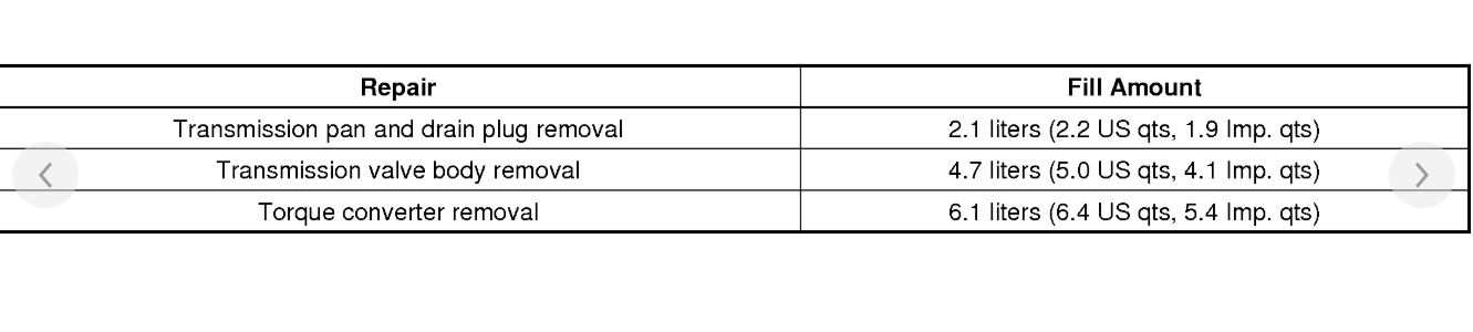
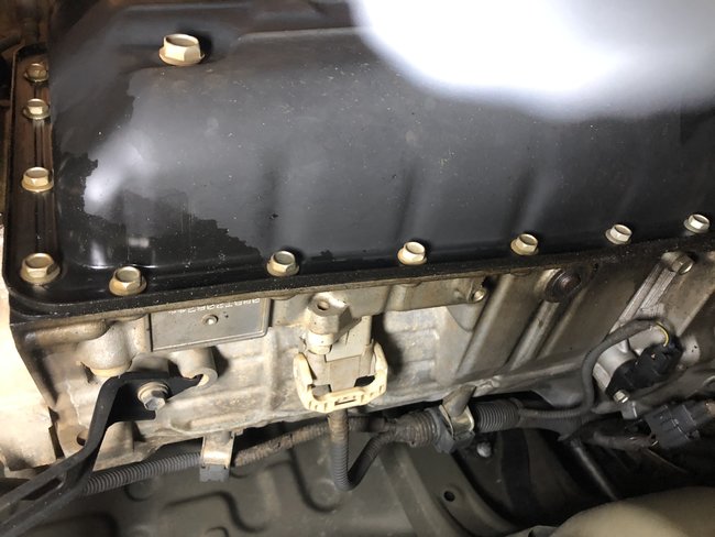
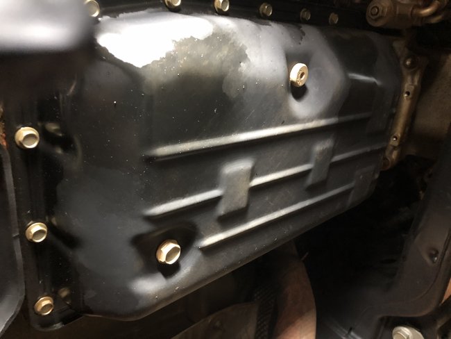
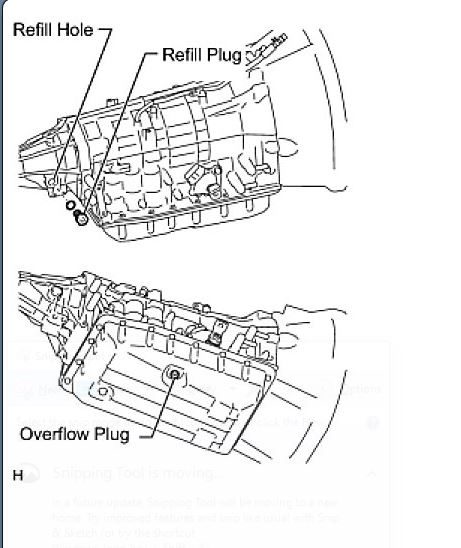
The 2757 is for the transmission. Did you ever change the fluid and filter in the transmission? A common issue is a dirty valve body from contaminated fluid.

https://www.2carpros.com/articles/automatic-transmission-problems

https://www.2carpros.com/articles/how-to-service-an-automatic-transmission

Roy


1201

BRAKE CONTROL: VEHICLE STABILITY CONTROL SYSTEM: C1201/51: Engine Control System Malfunction

DTC C1201/51 - Engine Control System Malfunction

DESCRIPTION

If a malfunction in the engine control system is detected through the CAN, the operations of VSC and TRAC are prohibited by the fail-safe function. When the signals from the engine are input normally, the fail-safe is canceled and the DTC is stored.


image


INSPECTION PROCEDURE

NOTE: When replacing the VSC actuator assembly, perform zero point calibration (See: Antilock Brakes / Traction Control Systems > Programming and Relearning > Calibration).

PROCEDURE

1. CHECK DTC (FOR SFI SYSTEM)
(a)for 1GR-FE:
Clear the DTC (SFI system) (See: Computers and Control Systems > Reading and Clearing Diagnostic Trouble Codes > DTC Check / Clear).
for 2UZ-FE:
Clear the DTC (SFI system) (See: Computers and Control Systems > Reading and Clearing Diagnostic Trouble Codes > DTC Check / Clear).
for 3UR-FE:
Clear the DTC (SFI system) (See: Computers and Control Systems > Reading and Clearing Diagnostic Trouble Codes > DTC Check / Clear).
(b)for 1GR-FE:
Check the DTC (SFI system) (See: Computers and Control Systems > Reading and Clearing Diagnostic Trouble Codes > DTC Check / Clear).
for 2UZ-FE:
Check the DTC (SFI system) (See: Computers and Control Systems > Reading and Clearing Diagnostic Trouble Codes > DTC Check / Clear).
for 3UR-FE:
Check the DTC (SFI system) (See: Computers and Control Systems > Reading and Clearing Diagnostic Trouble Codes > DTC Check / Clear).

Result


image


D -- GO TO SFI SYSTEM
C -- GO TO SFI SYSTEM
B -- GO TO SFI SYSTEM
A -- USE SIMULATION METHOD TO CHECK

2757

MONITOR DESCRIPTION

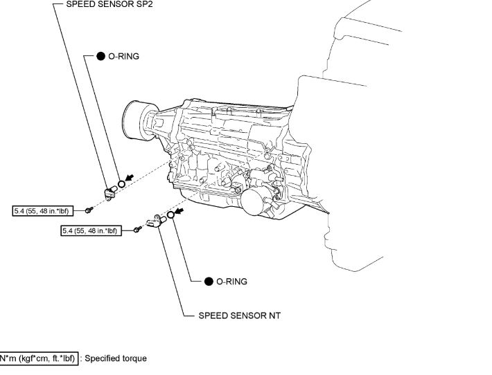
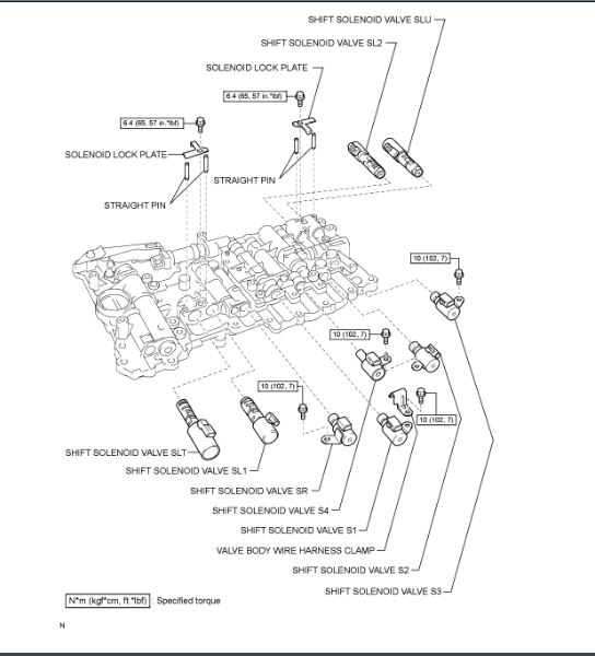
Torque converter lock-up is controlled by the ECM based on the turbine (input) speed sensor NT, output speed sensor SP2, engine rpm, engine load, engine temperature, vehicle speed, transmission temperature, and gear selection. The ECM determines the lock-up status of the torque converter by comparing the engine rpm (NE) to the input turbine rpm (NT). The ECM calculates the actual transmission gear by comparing input turbine rpm (NT) to output shaft rpm (SP2). When conditions are appropriate, the ECM requests lock-up by applying control voltage to shift solenoid SLU. When SLU is turned ON, it applies pressure to the lock-up relay valve and locks the torque converter clutch.
If the ECM detects no lock-up after lock-up has been requested or if it detects lock-up when it is not requested, the ECM interprets this as a fault in the shift solenoid valve SLU or lock-up system performance.
The ECM will illuminate the MIL and store the DTC.
Example:
When one of the following conditions is met, the system determines that there is a malfunction.

There is a difference in rotation between the input side (engine speed) and output side (input turbine speed) of the torque converter when the ECM commands lock-up ON.
Engine speed is at least 70 rpm greater than input turbine speed.
There is no difference in rotation between the input side (engine speed) and output side (input turbine speed) of the torque converter when the ECM commands lock-up OFF.
The difference between engine speed and input turbine speed is less than 35 rpm.
May 3, 2020 at 6:11 AM
Avatar
NASER NASER
  • MEMBER
  • 836 POSTS
Can i go ahead and replace that solenoid once i replace the fluid? If so how?
May 3, 2020 at 9:09 PM
Advertisement
Avatar
ASEMASTER6371
  • CERTIFIED EXPERT
  • 52,796 POSTS
The sensors the code is referring to are on the side of the transmission.

I attached a picture for you of the location. I doubt it is them as all they are doing is sending a signal. The code does not indicate a sensor failure.

Roy
May 4, 2020 at 2:07 AM
Avatar
NASER NASER
  • MEMBER
  • 836 POSTS
The sensor is for a lock up torque converter switch which should be inside the transmission once the pan is off.
May 4, 2020 at 5:28 AM
Avatar
ASEMASTER6371
  • CERTIFIED EXPERT
  • 52,796 POSTS
Correct but if there was an issue with the converter lock up , you would have a code for it, which you do not.

There is no lock up solenoid. It is a shift solenoid which opens a passage for the torque converter clutch to lock up.

I attached a picture of the shift solenoids and there locations for you.

Roy

May 4, 2020 at 5:44 AM
Avatar
NASER NASER
  • MEMBER
  • 836 POSTS
hmm, so what does it indicate a failure of what? so dirty or old fluid is a possibility is what you saying, and that I should do that first and see how it goes?
May 4, 2020 at 5:46 AM
Avatar
ASEMASTER6371
  • CERTIFIED EXPERT
  • 52,796 POSTS
Do you have a scan tool that can read live data for the transmission? You need to see the signals from the speed sensor as they are the signal that is monitored for the control of the shift solenoids.

I would start with the service, yes. dirty fluid could cause valves not to work correctly.

Roy
May 4, 2020 at 5:50 AM
Avatar
NASER NASER
  • MEMBER
  • 836 POSTS
ya, I have scanners that can do that. any specific ones I should look for? so basically drive it and get the numbers for them?
May 4, 2020 at 5:51 AM
Avatar
ASEMASTER6371
  • CERTIFIED EXPERT
  • 52,796 POSTS
Snap on are good. You need to monitor the input and output speed sensors and make sure they are sending there signals.

Activate all the shift solenoids manually as well to be sure when they are activated, the correct gear is activated.

Roy
May 4, 2020 at 6:07 AM
Avatar
NASER NASER
  • MEMBER
  • 836 POSTS
Can you give me instructions on replacing the fluid, drain and fill, for this truck listed at the top? I am sure it isn't difficult but just to be sure.
May 4, 2020 at 8:39 AM
Avatar
ASEMASTER6371
  • CERTIFIED EXPERT
  • 52,796 POSTS
This is like the old Ford transmissions. There is a large plug on the bottom of the pan with a small plug in the center of the big plug.

Remove the big plug for draining all the fluid. then when refilling, you do it from the side of the transmission. You remove the small plug in the pan and when the fluid level is correct, it will spill out the plug.

Roy

1. BEFORE FILLING TRANSMISSION

This transmission requires Toyota Genuine ATF WS transmission fluid.
After servicing the transmission, you must refill the transmission with the correct amount of fluid.
Maintain the vehicle in a horizontal position while adjusting the fluid level.
Proceed to the "Transmission Pan Fill" procedures if you replaced the entire transmission, transmission pan, drain plug, valve body and/or torque converter.
Proceed to the "Transmission Fill" procedures after removing the refill plug if you replaced the transmission hose and/or output shaft oil seal.


imageOpen In New TabZoom/Print


2. TRANSMISSION PAN FILL
(a)Remove the refill plug and overflow plug.
(b)Fill the transmission through the refill hole until fluid begins to trickle out of the overflow tube.
(c)Reinstall the overflow plug.
3. TRANSMISSION FILL
(a)w/ Trailer Towing System (w/ Thermostat):
Push the shaft of the thermostat and fix it in place.


imageOpen In New TabZoom/Print


(1)By using compressed air, etc., blow dust off of the thermostat cap to clean it.
(2)Using a screwdriver, push the shaft of the thermostat.

HINT:


imageOpen In New TabZoom/Print


Pushed amount: 5.5 to 7.0 mm (0.217 to 0.276 in.)
Push the shaft until the screwdriver contacts the step inside the cap.

(3)With the shaft of the thermostat pressed, push a pin (diameter: 1.0 to 1.8 mm (0.0394 to 0.0709 in.)) into a hole on the side of the thermostat cap. Insert the pin until it passes through the hole on the other side of the thermostat cap to fix the shaft in place.
(b)Fill the transmission with the amount of fluid listed in the table below.
Standard capacity:
May 4, 2020 at 8:57 AM
Avatar
NASER NASER
  • MEMBER
  • 836 POSTS
is that with the engine running like most German cars or can this be done while cold? and engine off?
May 5, 2020 at 3:22 PM
Avatar
ASEMASTER6371
  • CERTIFIED EXPERT
  • 52,796 POSTS
When filling, it is done with the engine off.

Roy
May 5, 2020 at 3:28 PM
Avatar
NASER NASER
  • MEMBER
  • 836 POSTS
The pictures i have look different, two drain plugs one 14 mm or so appears to be the one to drain everything and the allen key one to front right of pan is the overflow i assume, no fill plug like the picture, i only see one on back right of transmission. does this look like it?
May 5, 2020 at 3:39 PM
Avatar
NASER NASER
  • MEMBER
  • 836 POSTS
I have the 4.7l.
May 5, 2020 at 3:42 PM
Avatar
ASEMASTER6371
  • CERTIFIED EXPERT
  • 52,796 POSTS
Is this the one?

Roy
May 5, 2020 at 3:48 PM
Avatar
NASER NASER
  • MEMBER
  • 836 POSTS
Yup that's it, i figured the other one is for the 5.7 i believe. Some say heat it to 130f then check the overflow but will it work the same if i just fill while engine off and watch the overflow?
May 5, 2020 at 4:08 PM
Avatar
ASEMASTER6371
  • CERTIFIED EXPERT
  • 52,796 POSTS
I would fill it to the max. Then run the engine to normal operating temperature and then shut it off and check the level.

Roy
May 5, 2020 at 4:29 PM
Avatar
NASER NASER
  • MEMBER
  • 836 POSTS
What does pushing the pin in the transmission thermostat do? Why Is that mentioned when filling the fluid?
May 6, 2020 at 4:34 PM
Avatar
ASEMASTER6371
  • CERTIFIED EXPERT
  • 52,796 POSTS
The thermostat is like the one in the cooling system for circulation. When you push it open, all the air leaves so the fluid level will not drop in the future.

Roy
May 6, 2020 at 4:50 PM
Avatar
NASER NASER
  • MEMBER
  • 836 POSTS
I see but it doesn't say when i should do that. When filling it cold until it comes out of overflow plug, push the pin in and start the car, let it get warm, then add more? If i do that i wouldn't be able to know what temperature is the fluid at since i use the scanner and i assume the pin am gonna push has to do with telling me what temperature it is? Can you confirm from somewhere that it is a 130f before i open it up and add more? I drained twice now , black, without pushing the pin and it has gotten somewhat worse feels like it's low on fluid. So not sure when I should push the pin in and when i should release it.
May 6, 2020 at 5:26 PM
Avatar
ASEMASTER6371
  • CERTIFIED EXPERT
  • 52,796 POSTS
I would push the pin in when you are filling it.

That is allowing the air to leave so fluid can enter the system.
If you have air, it will feel that way as the fluid is low.

As far as the temperature, I was looking and it opens at 120.

Roy
May 6, 2020 at 5:40 PM