Code p0688?

2004 DODGE STRATUS
159,000 MILES • 2.7L • 6 CYL • 2WD • AUTOMATIC
Avatar
DAMUALBERT21
  • MEMBER
  • 18 POSTS
changed PCM and ASD relay. The crank sensor wire was broken i fixed it along with a new sensor. Also, I need a wiring diagram for said car.
Feb 12, 2024 at 10:10 AM
Advertisement
Avatar
AL514
  • CERTIFIED EXPERT
  • 5,465 POSTS
Hello, we can post a wiring diagram for you on this, have you checked for power at the ASD relay location with the key on? I'll grab the wiring diagrams for you.
Feb 12, 2024 at 11:07 AM
Avatar
AL514
  • CERTIFIED EXPERT
  • 5,465 POSTS
With the ASD Relay out, and key on you should have power (12v) on 2 of the relay's pins, just don't spread the pins where the relay lives with a test light or meter leads, just touch the pins to get a voltage reading. In this case it would be best to use a multimeter to start with, just to verify there is a full 12volts at both relay pins.
This code setting is due to no voltage present at the PCM pin 46 (Fused B+) pin. So, there might be a broken wire in between the PCM and ASD Relay location. I remember these vehicles having a lot of corroded connectors back in those years. If you need further wiring diagrams just let us know.

There are also a couple differences for "Early Model" and Late Model builds for that year. Some of the PCM connectors can have just 40 pins, 38 pins or 38 pin connectors with another connector going from pins 41-80, so if you see something different you can leave your VIN and we can look the vehicle up that way.

https://www.2carpros.com/articles/how-to-use-a-voltmeter

https://www.2carpros.com/articles/how-to-use-a-test-light-circuit-tester

https://www.2carpros.com/articles/how-to-check-an-electrical-relay-and-wiring-control-circuit
Feb 12, 2024 at 11:18 AM
Advertisement
Avatar
DAMUALBERT21
  • MEMBER
  • 18 POSTS
I checked the ASD relay it was at 12 volts the PCM relay was reading 10 volts.
Feb 12, 2024 at 12:39 PM
Avatar
DAMUALBERT21
  • MEMBER
  • 18 POSTS
Reading
Feb 12, 2024 at 12:42 PM
Avatar
DAMUALBERT21
  • MEMBER
  • 18 POSTS
Also, it cranks starts then stalls.
Feb 12, 2024 at 12:44 PM
Avatar
AL514
  • CERTIFIED EXPERT
  • 5,465 POSTS
The PCM relay is reading 10volts on both pins? I'm going to look in OEM wiring diagrams because I don't even see a PCM relay in the aftermarket diagrams.
Feb 12, 2024 at 1:20 PM
Avatar
DAMUALBERT21
  • MEMBER
  • 18 POSTS
I meant fuse PCM is on a 30 fuse.
Feb 12, 2024 at 1:21 PM
Avatar
AL514
  • CERTIFIED EXPERT
  • 5,465 POSTS
Okay, Fuse 14 30amp feeds the PCM and ASD Relay, so are you saying you have 10volts at that fuse but 12volts at the ASD Relay? There is a splice where power splits off to the PCM and then to the two ASD Relay feeds, the Splice looks to be internal to the Power Distribution Center where the ASD Relay and that fuse is located.

So here's the test we need you to do, with the key On, not cranking, just measure the voltage from the Fuse 14 30amp to either of the ASD Relay feeds with the relay out.

Can you also measure from Battery Positive to Fuse 14, I think you may find a 2volt roughly, but check that as well real quick.

And then Fuse 14 to any other Fuse in that box, such as Fuse 2 20amp, Fuse 4 40amp, Fuse 6 40amp, etc. i just want to see if there are any other voltage drops in that fuse center

We need to see if there is any voltage drop occurring between the Fuse 14 and the ASD Relay location. I think these wiring diagrams are not complete for internal circuits inside the Power Dist Center. I'm going through the OEM wiring diagrams right now. But I'm wondering if there is a cracked solder joint inside the Power Dist Center.
Feb 12, 2024 at 1:37 PM
Avatar
AL514
  • CERTIFIED EXPERT
  • 5,465 POSTS
I'm not sure this diagram is correct, if you have 10 volts at that fuse and 12 at the ASD relay,
You can see all of these Splices are internal to the PDC, so a crack in any of those solder joints can cause an issue like this, especially with the Fuel Pump relay being on one of these splices, when a cracked solder joint gets hot due to current flow, the gap in the crack can widen causing intermittent issues like this.
Feb 12, 2024 at 1:41 PM
Avatar
AL514
  • CERTIFIED EXPERT
  • 5,465 POSTS
I almost want to have you put 12-volts to fuse 14 (the fuse at 10volts) and see if the engine starts. That low voltage at a fuse like that can be internal to this design of the PDCenter. Id like to pull it apart and solder up any broken joints inside. Shouldn't be too hard to do. I would also check to see if there is low voltage on any other fuses. Because that with any voltage drop readings to B+ would give a clearer indication of what might be going on here.
Feb 12, 2024 at 2:15 PM
Avatar
DAMUALBERT21
  • MEMBER
  • 18 POSTS
You talking of running a jumper at 12 volts to fuse 14?
Feb 12, 2024 at 2:57 PM
Avatar
AL514
  • CERTIFIED EXPERT
  • 5,465 POSTS
If the voltage is reading only 10-volts there, you would only be bypassing the internal circuits of the Power Distribution Center, when you measured the voltage there did you have the Fuse 14 out? Is it one of those encased fuses? I'm just wondering if both pins where the fuse sits has only 10 volts. And do any other fuses in that box read the same?
Diagram 1 below shows the internals of the PDC, you can see it's a straight feed from the battery.
Feb 12, 2024 at 3:01 PM
Avatar
AL514
  • CERTIFIED EXPERT
  • 5,465 POSTS
Double check your readings though, make sure that's really what you have on that fuse. I'm not sure how you are getting 12v on the ASD relay since its fed by Fuse 14. Did you have the relay out when checking the 10-volts?
Feb 12, 2024 at 3:05 PM
Avatar
DAMUALBERT21
  • MEMBER
  • 18 POSTS
I have both the ASD relay and the PCM 30 am VOS fuse out with ignition off I am getting 12 volts on both with ignition on PCM drops to 10.3 volt.
Feb 12, 2024 at 3:13 PM
Avatar
AL514
  • CERTIFIED EXPERT
  • 5,465 POSTS
And this must also drop the ASD voltage down as well, correct?
Try this test with the ignition on. That low voltage has to be causing the P0688 code; We just need to find out what is causing the drop off like that. Is it something inside the Power Dist Cent, or something after the fuse pulling the circuit down? the 2nd diagram shows it's a pretty straight shot from the Battery.
Fuse 14 has 2 legs on it, one coming from the battery and the other going to the relay, that's why I am asking if both legs of Fuse 14 drop to 10-volts.
Feb 12, 2024 at 3:25 PM
Avatar
AL514
  • CERTIFIED EXPERT
  • 5,465 POSTS
This is some good info on the ASD Relay sense circuit for the PCM.
Feb 12, 2024 at 3:33 PM
Avatar
DAMUALBERT21
  • MEMBER
  • 18 POSTS
yes, both legs drop to 10 volts as soon as the ignition is on battery is charged now as well with ignition off its reading 13 volts as soon as its on jumps right down.
Feb 12, 2024 at 3:38 PM
Avatar
DAMUALBERT21
  • MEMBER
  • 18 POSTS
i did notice a ground that's attached to the strut tower coming out of the PDC is corroded.
Feb 12, 2024 at 3:39 PM
Avatar
AL514
  • CERTIFIED EXPERT
  • 5,465 POSTS
Okay, did you happen to notice any corrosion inside the PCM connectors while you were placing it? I'm going through TSB and Recall info. here and there are some issues with the PCM connector seals being out of place. It doesn't apply to all vehicles, but this is a Recall. I'm going to post this for you. It's very strange that both legs of the fuse drop off like that, really only the leg of the fuse that's connected to battery power should even have voltage on it.
With the fuse out, the 2nd leg should be at 0volts. Thats what is confusing here.
Feb 12, 2024 at 3:46 PM
Avatar
AL514
  • CERTIFIED EXPERT
  • 5,465 POSTS
Okay, does the PDC have connectors on the bottom of it you can inspect for corrosion?
Feb 12, 2024 at 3:46 PM
Avatar
AL514
  • CERTIFIED EXPERT
  • 5,465 POSTS
This is the Recall notice on the PCM connector seals, although I would check other connectors and repair any corroded grounds.
Feb 12, 2024 at 3:51 PM
Avatar
AL514
  • CERTIFIED EXPERT
  • 5,465 POSTS
With the start and stall, it sounds like the fuel pump is at least working during start up. And power is possibly being lost to either fuel injectors, ignition coils or both since they are on the ASD circuit. The ASD should be energized as soon as the engine hits 50rpm and that will power injectors and coils, and everything should fire off. But clean that Ground up really good, a bad ground can cause that voltage drop to happen when the circuit is under a load as at start up. That could definitely be an issue.
Feb 12, 2024 at 4:02 PM
Avatar
AL514
  • CERTIFIED EXPERT
  • 5,465 POSTS
Heres G100 and G108 grounding locations.
Is this really the battery location (diagram 3)?
Feb 12, 2024 at 4:18 PM
Avatar
AL514
  • CERTIFIED EXPERT
  • 5,465 POSTS
The PCM may be grounded through its case on some builds, so verify that's good too.
Feb 12, 2024 at 4:28 PM
Avatar
DAMUALBERT21
  • MEMBER
  • 18 POSTS
i will check all grounds also i am getting power to all coils its the fuel injectors that cut out as soon as it starts if i spray starter fluid in it itll run longer i will also have to check that pcm seal im assuming it was never replaced and the car sat for a long time so im sure something could've leaked in that is the battery location as well
Feb 12, 2024 at 4:38 PM
Avatar
AL514
  • CERTIFIED EXPERT
  • 5,465 POSTS
Okay, that's good to know. The coils and injectors are powered off the same feeds. If the vehicle sat for more than 6-8 months, then the gas in the tank is no good. especially if it sat with a half-filled tank or so. If it will run off of an alternate fuel source, then drain the tank out and replace the gas. Change the fuel filter too. I have seen many vehicles not start just because of bad gas, even have seen a (supposedly) fresh tank of gas burn out 3 ignition coils and then the PCM because the coils got so hot then shorted out. So, there might be more than one issue here. But I have all the PCM connector pinouts pulled up already, there are different designs for this one of course. There should be a sticker either in the driver's door frame or under the hood that will have a year with a month before it, and since these are Early and Late Build dates that will help narrow down the PCM connectors. You can check if the ASD output to the PCM is being lost, I think it might be that the vehicle can't stay running long enough.
Feb 12, 2024 at 5:07 PM
Avatar
DAMUALBERT21
  • MEMBER
  • 18 POSTS
Could that green and tan ground? Wire cause that code it grounds all the coils and injectors.
Feb 19, 2024 at 12:26 PM
Avatar
AL514
  • CERTIFIED EXPERT
  • 5,465 POSTS
I don't think that would cause the ASD relay code, but that's a really bad looking ground, since that tab the connector slides onto is so rusted, I would run a wire from that connector to battery negative for testing purposes, just to rule it out. And then go to the PCM connector and see if 12v is making it to the ASD Relay output pin on PCM connector. I'll post these PCM connectors, you will have to determine which PCM you have, the Early Build and Late Build look to have different pin locations for the ASD output, which is where the PCM is sensing the 12volts from the relay. If it's not there, the P0688 code sets.
The way they have these connectors is a bit confusing, so go by the information at the top of each diagram, and you'll have to identify the correct wire by matching up the colors per connector. So, for example, looking at Ci (sbec Early Build) the ASD relay output pin will be pin 6 dark green/orange, with pin 5 being a yellow/red wire and pin 7 being a yellow/white wire. When diagrams get to be confusing like this, it's best to match up other wire colors positions in relation to the wire you're trying to locate, this way you are sure you have the correct wire.
And you may need to use a wire piercing probe to connect to this wire and have someone crank the engine for you while you are monitoring the voltage level. Its not always are good idea to back probe PCM connectors because they can be damaged, or the back probe can short out to the pin next to it damaging the PCM itself.
I'm still suspicious of the 10volts on fuse 14. That is what is probably causing the P0688 code
Something is dropping that voltage off and there shouldn't be 10 volts on each leg of the fuse location with the fuse out. try using a test light with the fuse out and see if it lights. There might be voltage feeding back somehow to the other side of the fuse. I really would like to see that.
Feb 20, 2024 at 10:46 AM
Avatar
AL514
  • CERTIFIED EXPERT
  • 5,465 POSTS
This is what I'm questioning.
Feb 20, 2024 at 11:07 AM
Avatar
DAMUALBERT21
  • MEMBER
  • 18 POSTS
Okay, I'll run some tests see what I can figure out also that ground is on a resistor that's what plugs into that rusted ground.
Feb 20, 2024 at 11:14 AM
Avatar
DAMUALBERT21
  • MEMBER
  • 18 POSTS
Also cars manufactured date is 12/03.
Feb 20, 2024 at 11:30 AM
Avatar
AL514
  • CERTIFIED EXPERT
  • 5,465 POSTS
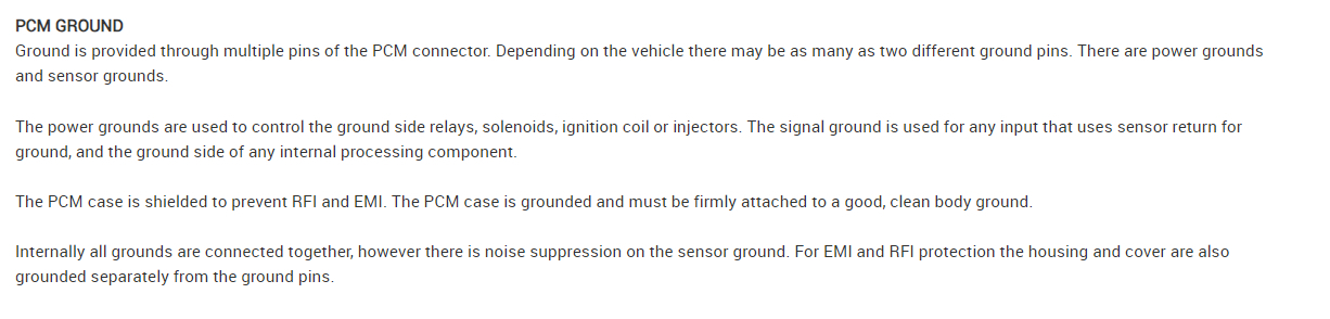
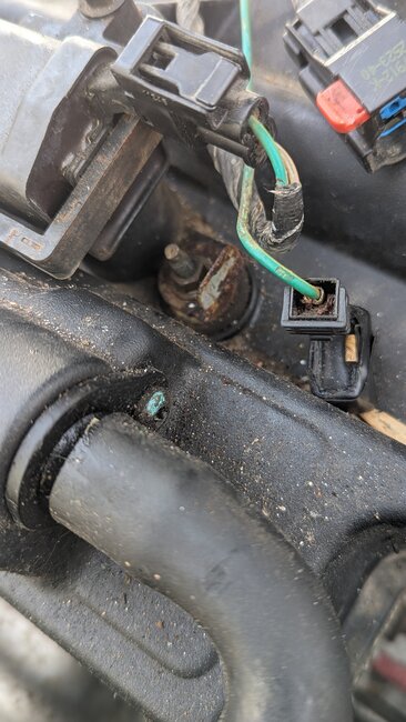
Okay, if that plug is a ground for the coils, it's not a resistor, it's a capacitor that helps suppress voltage spikes and noise that the coils can put out. The capacitor is internal to that black connector, correct?

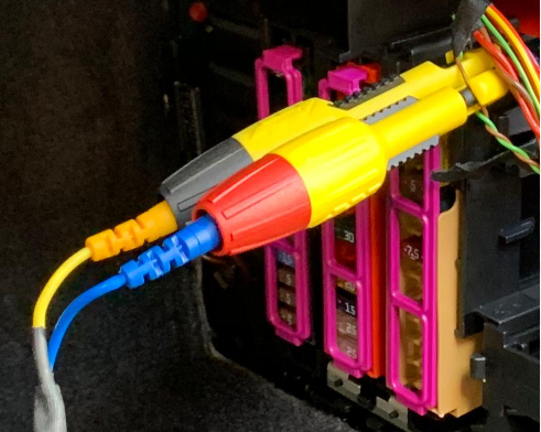
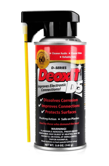
You can also use some terminal cleaner spray for inside the connector to clean out any corrosion that is in there. Any auto parts store will carry terminal spray. Deoxit D5 is the best, although I have used other brands as well. The Deoxit can be a little expensive. The 1st pic below is a wire piercing probe, I use the ones that have a single tip that will just pierce the wire insulation and not damage the other wire strains inside. Then use some liquid electrical tape to seal up the tiny hole after testing. You can get that at walmart for about $10.
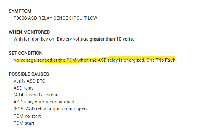
With the manufacture date I only see one connector labelled Late Build. and it doesnt include the ASD relay output.
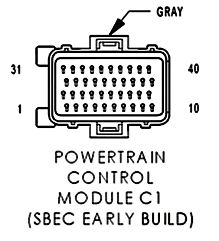
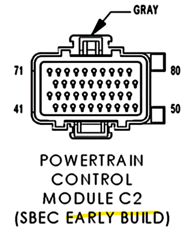
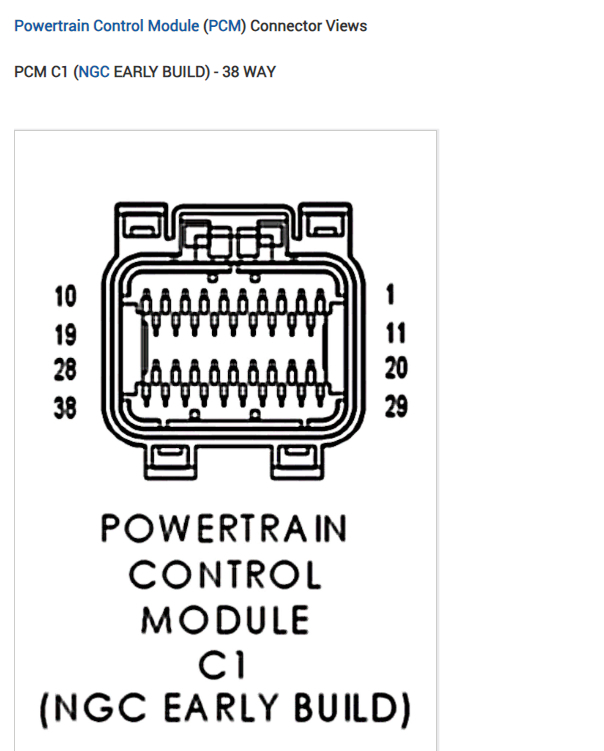
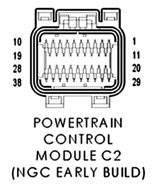
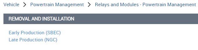
These are the only 2 options service info gives with the PCM connectors,
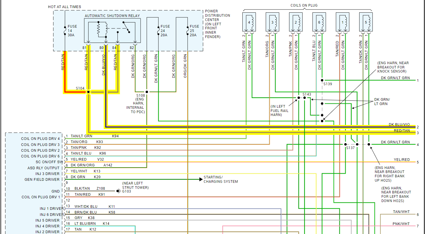
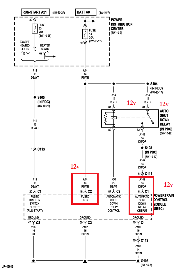
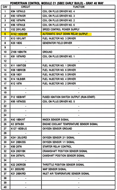
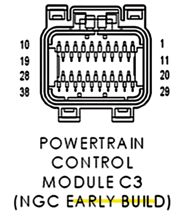
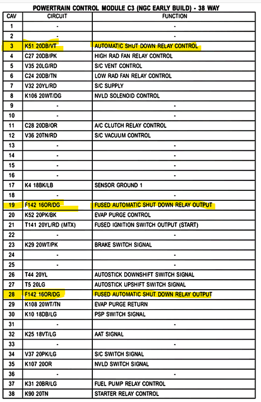
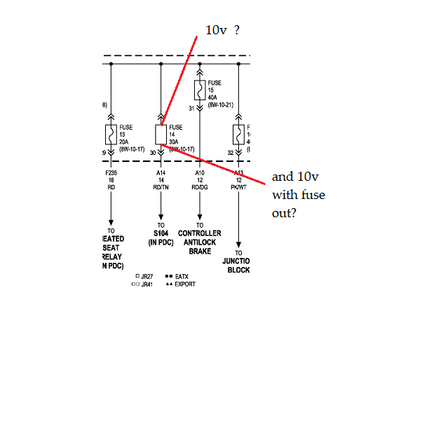
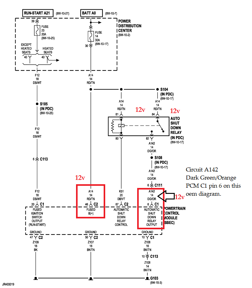
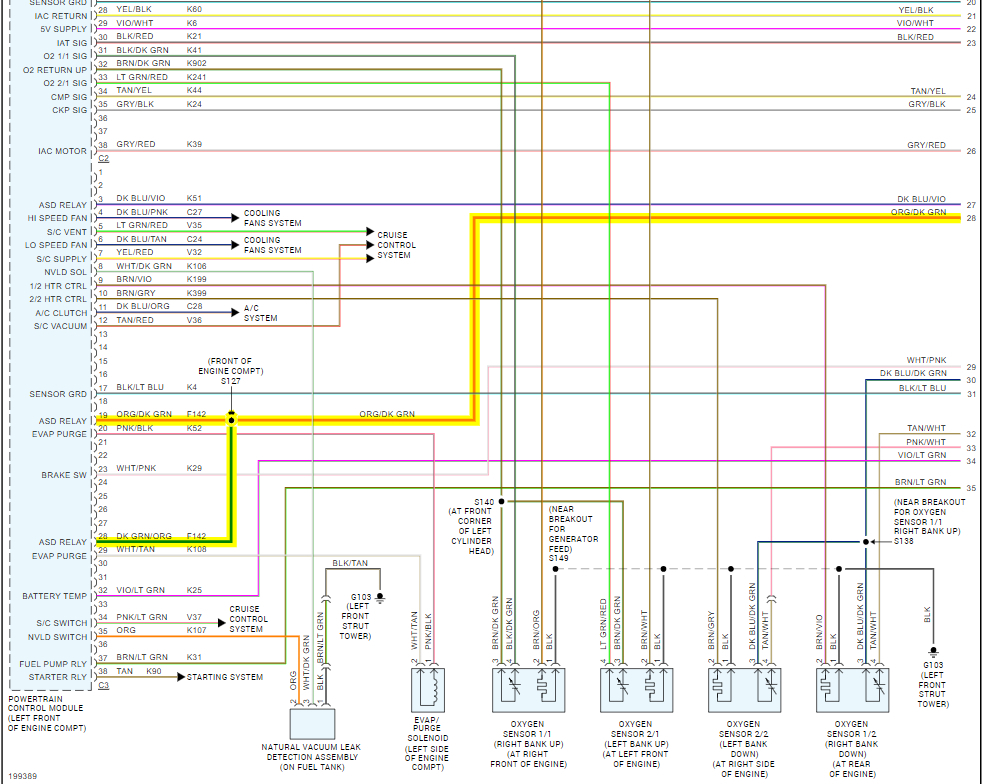
The circuit # is A142 (dark green/orange wire) on the OEM diagram, so it's either the SBEC C1 pin 6 or NGC C3 pins 19 and 28 orange/dark green wires.

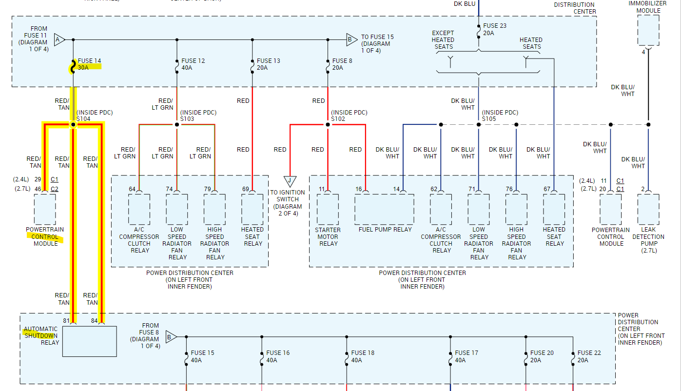
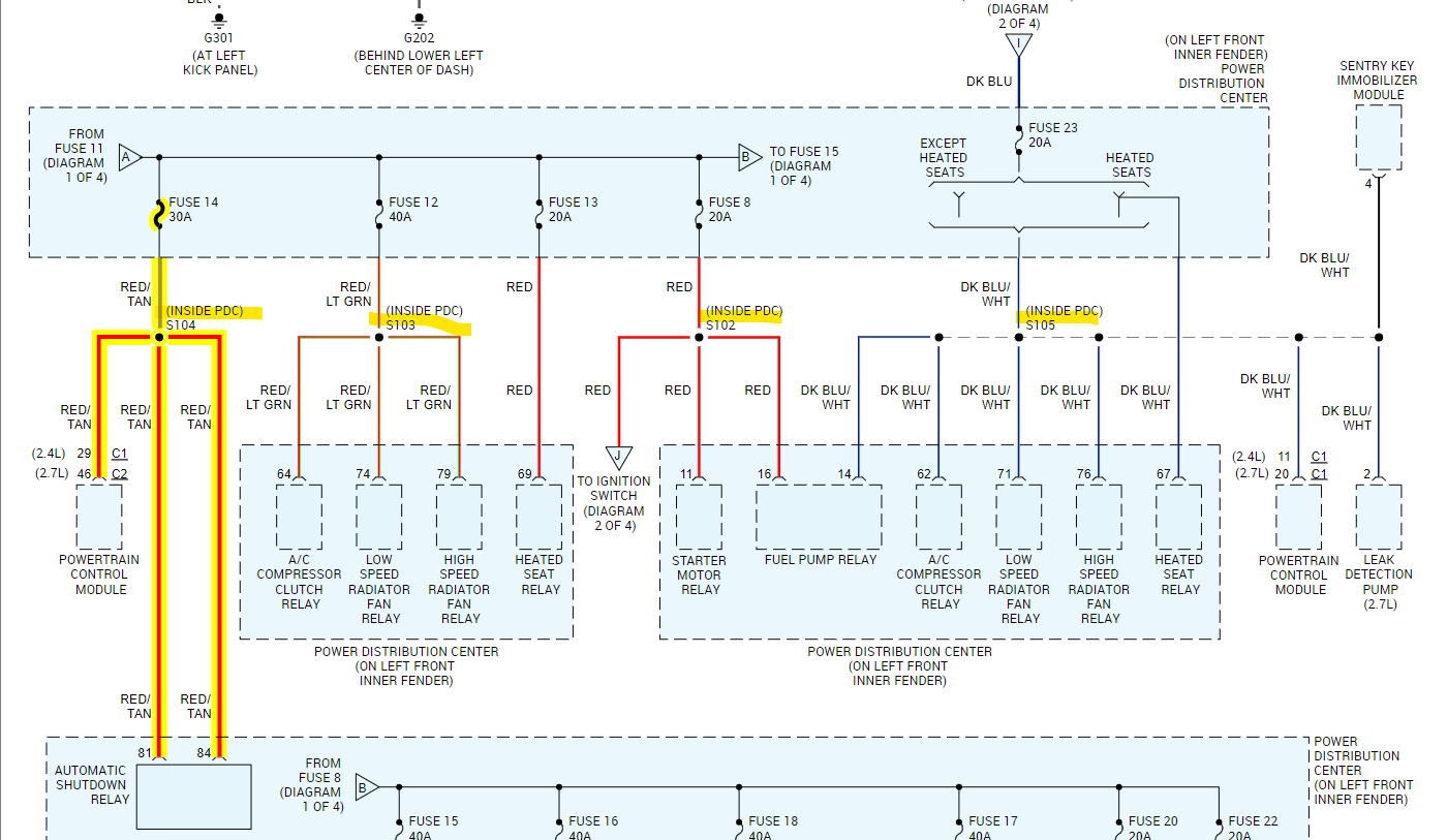
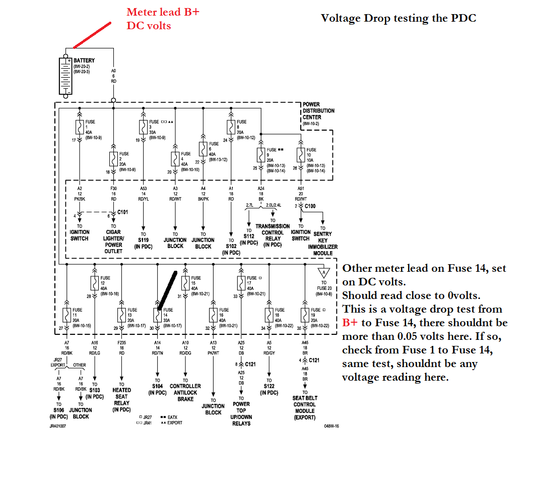
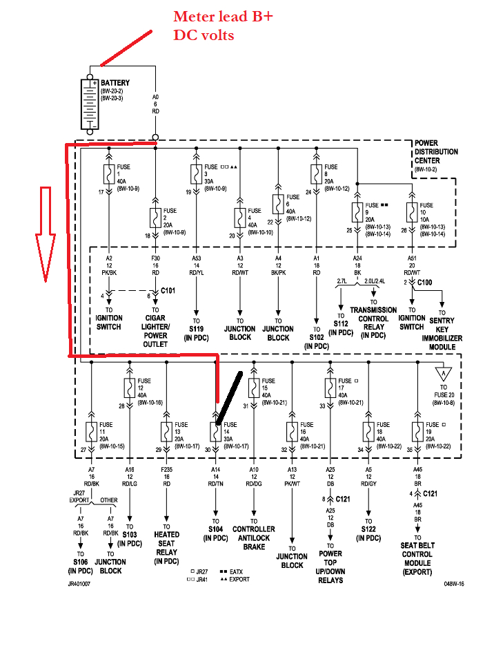
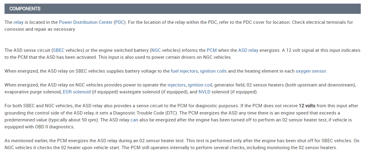
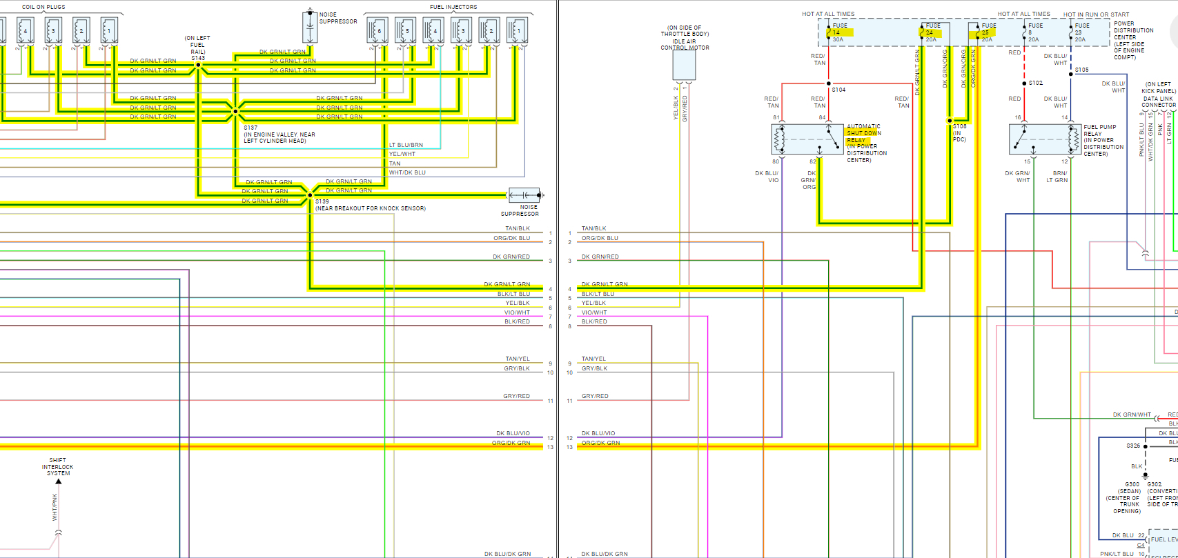
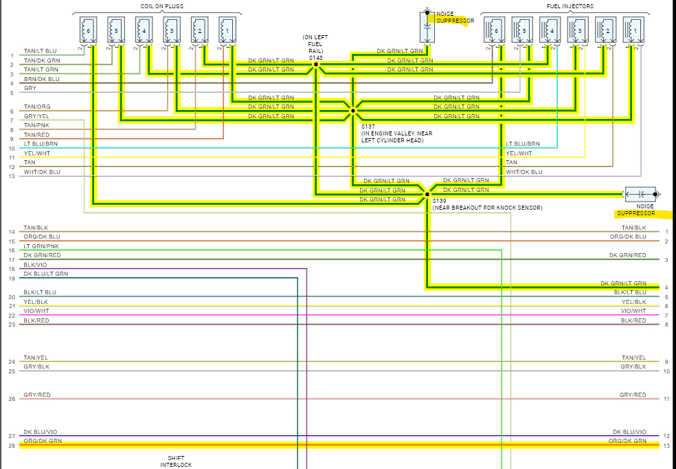
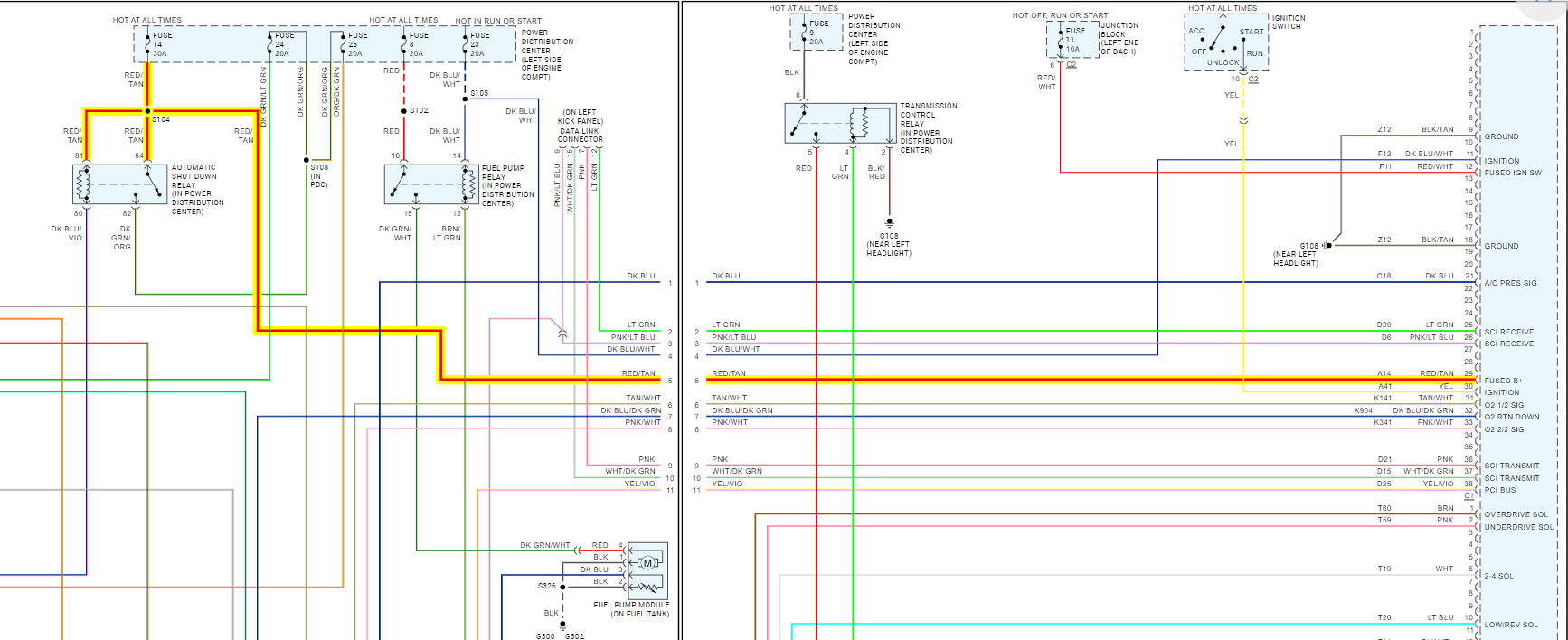
Diagrams 5,6,7 are the Late Build diagrams, which show the ASD Relay feeding fuses 24 and 25 (both 20A). Fuse 24 goes to the Coils and Injectors and Fuse 25 to the PCM at two pins. So, you could check those fuses, pull one at a time and see if it affects the 10-volt drop.
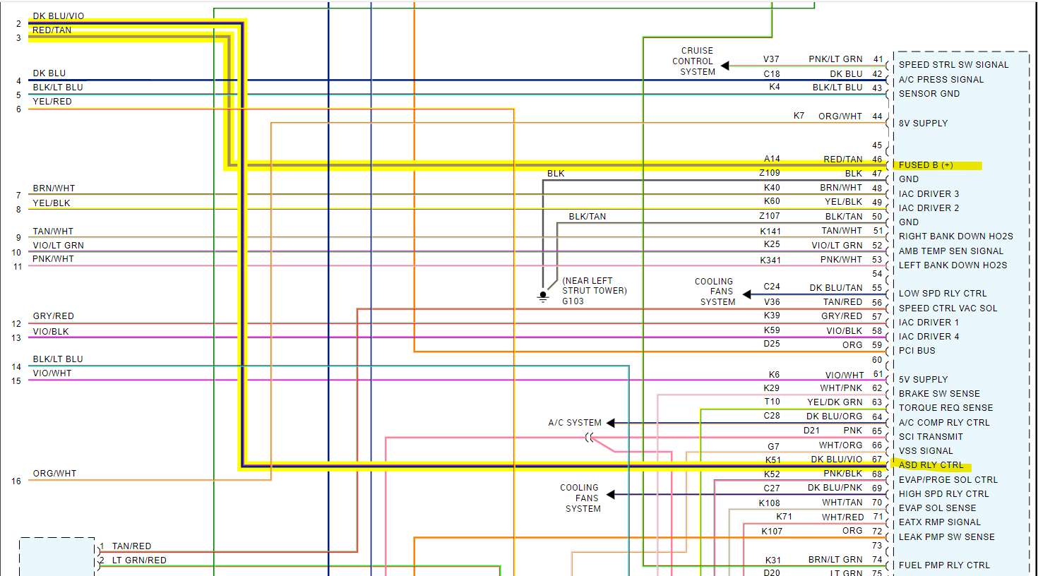
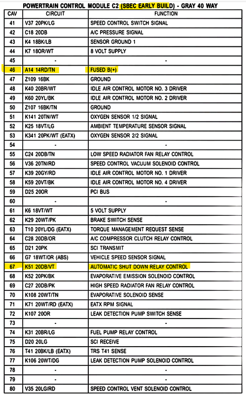
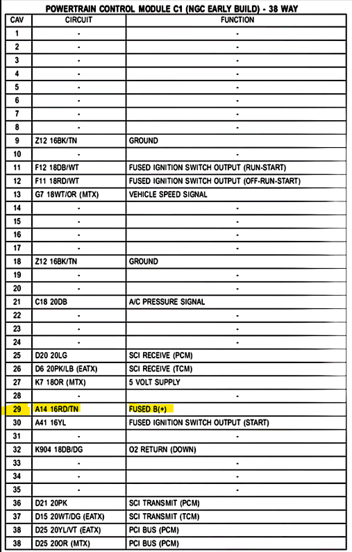
If either fuse does bring back battery voltage when pulled, that would give us some more direction. If there's no change with both Fuse 24 and 25 out, as well as the ASD relay out, Then the voltage drop has to be on that Red/Tan wire running to the PCM pin 29 labelled B+.
Hopefully these diagrams are correct, but those tests should tell us something.
Feb 20, 2024 at 12:27 PM
Avatar
DAMUALBERT21
  • MEMBER
  • 18 POSTS
It was the restor or capacitor it fired right up once I got that cleaned up and back together.
Feb 20, 2024 at 1:08 PM
Avatar
AL514
  • CERTIFIED EXPERT
  • 5,465 POSTS
No codes either?
Feb 20, 2024 at 1:31 PM
Avatar
AL514
  • CERTIFIED EXPERT
  • 5,465 POSTS
So, the code must have been setting because the engine couldn't run long enough.
Feb 20, 2024 at 1:32 PM
Avatar
DAMUALBERT21
  • MEMBER
  • 18 POSTS
02 codes right now but that's because a o2 sensor wire is broken.
Feb 20, 2024 at 1:32 PM
Avatar
DAMUALBERT21
  • MEMBER
  • 18 POSTS
That's what I was thinking too, but I've had her running for a half hour now and only things coming up now is that o2 code which is easy fix.
Feb 20, 2024 at 1:33 PM
Avatar
AL514
  • CERTIFIED EXPERT
  • 5,465 POSTS
That P0688 is a pretty misleading code, for sure.
Feb 20, 2024 at 1:34 PM
Avatar
DAMUALBERT21
  • MEMBER
  • 18 POSTS
It definitely is. thank you for all your help. I can fix money stuff when it comes to motors, but wiring makes my brain hurt.
Feb 20, 2024 at 1:35 PM
Avatar
AL514
  • CERTIFIED EXPERT
  • 5,465 POSTS
Well I'm glad you got it figured out, there should be 2 of those capacitors, so you may want to check the other one as well, there's one for the coils and one for the injectors.
Feb 20, 2024 at 1:35 PM