Good afternoon,
What brand converter did you use? Quality makes a huge difference. The cheaper units around 100 do not have enough precious metals inside to do the job. A good converter will cost anywhere from 350-600 depending on the brand. Walker and Bosal are the only ones we need. They have a 5 year, 50,000 mile warranty for the light.
https://www.2carpros.com/articles/bad-catalytic-converter-symptoms
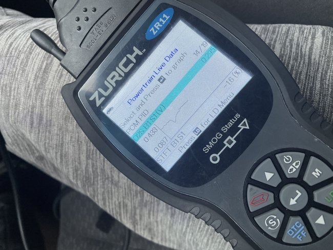
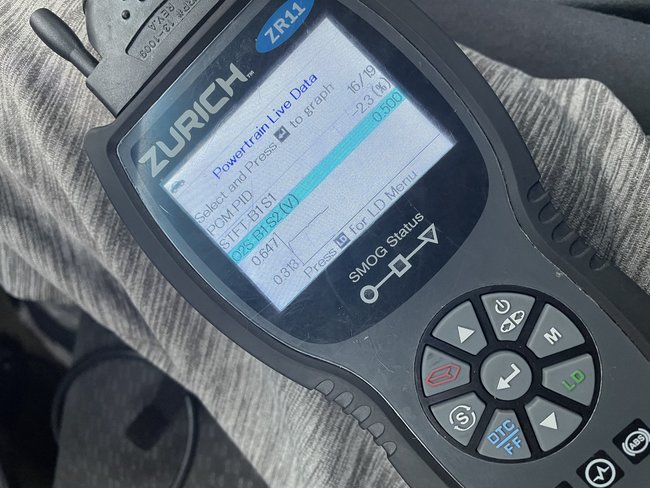
When you check the downstream sensor, test it at 1,200 RPMs, and see if the voltage is steady. If it varies, the cat is bad.
https://www.2carpros.com/articles/how-to-test-a-catalytic-converter
Roy
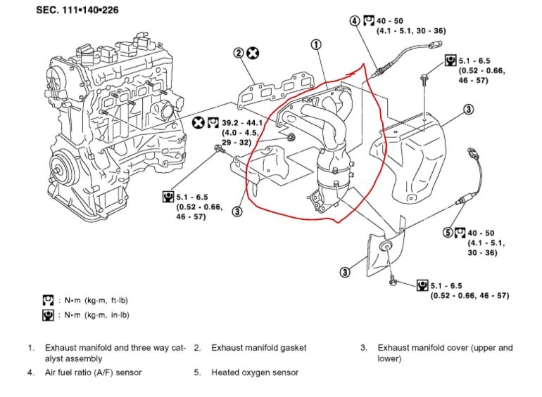
EXHAUST MANIFOLD AND THREE WAY CATALYST
imageOpen In New TabZoom/Print
Removal and Installation
REMOVAL
1. Remove the engine undercover using power tools.
2. Disconnect the electrical connector of heated oxygen sensor 1 or air fuel ratio (A/F) sensor 1, and unhook the harness from the bracket and middle clamp on the cover.
imageOpen In New TabZoom/Print
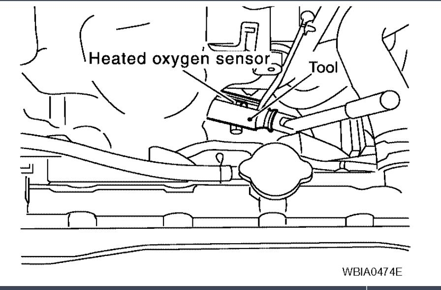
3. Remove the heated oxygen sensor 1 or air fuel ratio (A/F) sensor 1 using Tool.
Tool numbers
Air fuel ratio (A/F) sensor wrench : J-44626
Heated oxygen sensor wrench : KV10117100 (J-36471-A)
CAUTION:
Be careful not to damage heated oxygen sensor or air fuel ratio (A/F) sensor.
Discard any heated oxygen sensor or air fuel ratio (A/F) sensor which has been dropped from a height of more than 0.5 m (19.7 inch) onto a hard surface such as a concrete floor; use a new one.
4. Remove the lower exhaust manifold covers.
5. Remove the exhaust front tube. Refer to "Removal and Installation".
6. Remove the upper exhaust manifold cover.
imageOpen In New TabZoom/Print
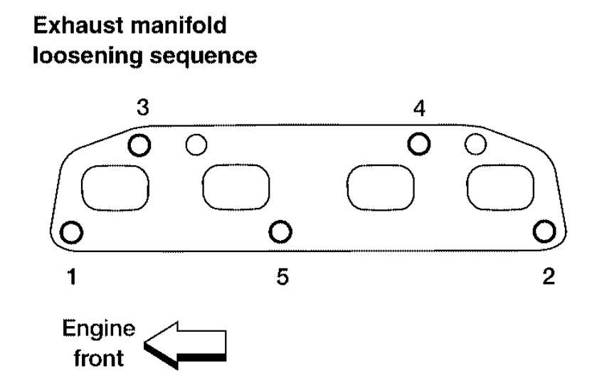
7. Loosen the nuts in the sequence as shown, on the exhaust manifold and three way catalyst.
8. Remove the exhaust manifold and three way catalyst assembly and gasket. Discard the gasket.
INSPECTION AFTER REMOVAL
Surface Distortion
imageOpen In New TabZoom/Print
Use a reliable straightedge and feeler gauge to check the flatness of exhaust manifold fitting surface.
Limit : 0.7 mm (0.0276 inch)
INSTALLATION
Installation is in the reverse order of removal. Pay attention to the following.
Tightening Exhaust Manifold Nuts
imageOpen In New TabZoom/Print
Tighten the nuts in the numerical order shown, to specification. After tightening No. 5, retighten No. 1 and then No. 3 to specification.
Installation of A/F Sensors and Heated Oxygen Sensors
Clean the A/F sensor and heated oxygen sensor threads with the Tool, then apply the anti-seize lubricant to the threads before installing the A/F sensor and heated oxygen sensors.
Tool number a: J-43897-18
b: J-43897-12
CAUTION: Do not overtighten the A/F sensors and heated oxygen sensors. Doing so may cause damage to the A/F sensors and heated oxygen sensors, resulting in a malfunction and the MIL coming on.
Images (Click to enlarge)
Jan 17, 2021 at 1:44 PM