OBD Port has no power?

2004 MINI COOPER S
149,000 MILES • 1.6L • 4 CYL • 2WD • MANUAL
Avatar
DAVE02903
  • MEMBER
  • 19 POSTS
Hi,

I have an OBD port on my car listed above with no power. I can't find any information on what fuse to check. Can you please help?

Thanks,
Dave
Aug 5, 2022 at 3:43 PM
Advertisement
Avatar
AL514
  • CERTIFIED EXPERT
  • 5,465 POSTS
Hello, check the back of the connector too, over the years they get used a lot, but there's two power feeds on this one.
Inspect this fuse panel for water intrusion on the back side as well. It may have corrosion on the pins underneath.

https://www.2carpros.com/articles/how-to-use-a-voltmeter
Aug 5, 2022 at 5:04 PM
Avatar
DAVE02903
  • MEMBER
  • 19 POSTS
Thank you for the information. I just bought this car so I'm just learning about it. I checked the fuses list in the diagram F3 and F36 and they are both good. I still have no power to the OBD port. I will try your other suggestion to remove the fuse box and check behind it for corrosion.

I have a second question. The fuse box under the hood has a 50A fuse for FL10 missing. I'm not sure if there should be a fuse there and what it is for. Any help would be appreciated.

Thanks
Dave
Aug 6, 2022 at 5:42 AM
Advertisement
Avatar
AL514
  • CERTIFIED EXPERT
  • 5,465 POSTS
Try taking those two fuses out and inspect them up close and take a look into the female pins where they go. See if there's any sign of corrosion. Also, when you checked for power at the DLC how where you checked it? Were you using a multimeter and what were you using for Ground? If you didn't, try using pins 4 and 5 of the DLC and you have to have the key On. I'll try to find this missing FL10 50amp fuse, there's a bunch of other 50-amp fuses, it's a pretty high amperage circuit for those. And just lightly touch the pins, don't spread the pins on the DLC or you'll never get a scan tool to communicate.

Is there no label on the underside of the Fuse box cover? Also, the owner's manual in the glovebox should have all the fuses listed. So far, all I'm finding is the location of FL10, I'm going to keep looking, but check the manual as well.

Ok so it looks like FL10 50A is for "K416, Relay for Heated Front Screen" It's a Windshield defroster system. It might be some type of integrated defroster built into the windshield. The fuse might be out because there might be a short circuit in the window grid and they didn't want to replace the window, in some situations like that. But if your regular defrost works I wouldn't worry about it. The wiring diagrams for this car are very spotty and difficult to find for some reason.
Your main defrost actually uses the ac compressor to help frost the window because it will blow out very dry air and along with the heat this helps to get rid of the moisture a lot faster.

One other thing, is the Battery in the rear of the vehicle on this model? I've read that the battery connections get very corroded where it is located. So I would take a look at the Battery and any bulk connectors back there if it is located in the rear. Since you just got this vehicle a good look around at as many connections and wiring, as well as all the Ground connections to the body and engine block, might save you a lot of headaches in the future. Make sure all Ground locations are very clean and tight.
Aug 6, 2022 at 11:08 AM
Avatar
DAVE02903
  • MEMBER
  • 19 POSTS
Thanks for the info. Yes, I'm using a meter to check the voltage on the OBD port. I used pin 4 for the ground and pin 16 for the power. When I do that, I get a little less than 2 volts register. When I use pin 4 for a ground and touch the meter to both sides of the fuses F3 and F36 I get a little less than 12 volts on both sides of the fuse, so I think they are okay as well as pin 4 as a ground. So, it looks like I'm not getting full power on pin 16. I don't know where to go next. It's a 2004 so I don't have the manual.

Here are a couple of pictures of the fuse box under the hood:

Thanks for all your help.

Dave
Aug 6, 2022 at 11:58 AM
Avatar
AL514
  • CERTIFIED EXPERT
  • 5,465 POSTS
Are you getting power on Pin 1 of the DLC, or is that 2 volts as well? Only 2 volts on pin 16 means that red/blue/yellow (and I don't know why they are using 3 colors for 1 wire), but that wire has a poor connection somewhere or has a corroded connector. There is a lot of voltage drop on that wire. I'll try to see if I can find any connectors on that wire. These wiring diagrams are terrible. The aftermarket ones (which I'm showing you) are the only ones that show the whole circuit. The OEM ones are broken up into small pieces everywhere, so it's a bit slow going. Let me know if the Battery is in the rear of the vehicle. and I'll see if I can trace that F3 fuse some more. Were you able to get behind this driver side Footwell trim? If the Battery is in the rear of the vehicle, I'm guessing they are running this wire under that trim down by your left leg and towards the rear of the vehicle. It's probably in the worst place for a wire to be. most are.
Aug 6, 2022 at 12:21 PM
Avatar
DAVE02903
  • MEMBER
  • 19 POSTS
Okay, I will check Pin 1. Sorry I forgot to tell you the battery is in the rear, and it is a new battery.
I really appreciate your help. I just bought the car on Wednesday and if I can't get this fixed, I won't be able to get it inspected which is due. So, the car would be worthless.

Thanks again
Dave
Aug 6, 2022 at 12:25 PM
Avatar
DAVE02903
  • MEMBER
  • 19 POSTS
Oh yes, I wasn't able to get behind the driver side footwell trim. I was looking for some YouTube videos to see how to do that but couldn't find any. I will keep looking.

Dave
Aug 6, 2022 at 12:28 PM
Avatar
AL514
  • CERTIFIED EXPERT
  • 5,465 POSTS
Okay, the first diagram is your driver side foot well; the second is the backside of that fuse panel and connector X10200 is the connector for fuse F3. Check the entire area for water intrusion. A corroded connector is almost definitely why you are only getting around 2 volts. And as for your inspection, worst case scenario, we have your de-pin pin 16 and run a 12-volt wire to it to get through inspection, we'll have you tape up pin 16 really good so it can go back in the DCL later and not be shorted out.
From the look of where this fuse panel is, it's in the perfect spot for water intrusion.
Aug 6, 2022 at 12:32 PM
Avatar
AL514
  • CERTIFIED EXPERT
  • 5,465 POSTS
A lot of times the trim that runs along where the bottom of the front door will close against will pull up and have plastic tabs underneath them that snap back down when reinstalling them. I'm trying to find you a picture, but usually there will be one piece of trim overlapping another and they have to be removed first to get the section closer to the fuse panel out..

It's the Left Footwell Trim you're trying to get out. They have all kinds of names for everything, for example the Pillar "A" is the upper plastic strip going to the roof. I'm having a lot of trouble finding the pictures. But the strip down by your left foot that runs along the bottom of the door opening probably just pops up and out, most do.
This picture is the passenger side door, but the piece I'm referring to is in green. That lower piece usually pulls up and has plastic tabs, we just need to get a look at the backside of that fuse panel where F3 is.
The fuse panel looks like it needs to be unbolted to come out.

Okay, I found something, this isn't shown on the aftermarket wiring diagrams, but there is a connector (X15) in between the Data Link Connector and Fuse F3, its under that plastic panel that the fuse box is in. If you have 12 volts at fuse F3 and not a pin 16, this connector looks like the only thing in the middle of the 2. So, I think you're going to find all the problems under that plastic panel in the 3rd picture below. Pin22 of connector X15 is the 12v power feed to the DLC.

If you find that there are any corroded connectors under there, then there might be a leak in the windshield seal or the door seal. That is a very common place for water intrusion.
Aug 6, 2022 at 12:51 PM
Avatar
DAVE02903
  • MEMBER
  • 19 POSTS
Thanks, I will try tomorrow to get the fuse panel off to get to the back of it. Thanks for giving me some hope about the inspection. I did check Pin 1 and pin4 together with the key on and i get 11.97 volts.

Dave
Aug 6, 2022 at 1:41 PM
Avatar
AL514
  • CERTIFIED EXPERT
  • 5,465 POSTS
Look above, there's more information.
Aug 6, 2022 at 1:42 PM
Avatar
DAVE02903
  • MEMBER
  • 19 POSTS
Good morning,

I finally got the panel off as well as the fuse box. There is some corrosion on the connectors. How do I remove that without damaging the connector? It is pretty tight I don't want to spread the pins by sticking something in. Is there some kind of spay I could use?

Dave
Aug 8, 2022 at 8:46 AM
Avatar
AL514
  • CERTIFIED EXPERT
  • 5,465 POSTS
Yes, there is terminal cleaning spray you can get. I think Deoxit is the best. And maybe use a small toothbrush with it, they have whole kits you can buy. but they're expensive. Look into the back of the connector too, see how bad it is in there as well. You need to get it as clean as possible, or it will just grow again, and spread through the whole connector and even short out pins together. Was it the X15 connector? It some situations where it's really bad we take the connector apart by de-pinning it and clean it that way. but try the spread and a small brush first.
Now the question is where did the moisture come from. To find water leaks, I close up the door and hold a hose over the window and door seal to see if any water gets inside. Having someone in the car with a flashlight helps a lot, to spot any drips of water. That whole fuse box could get corroded to the point where it would need to be replaced.

You can Google automotive terminal cleaning spray, but I think this one is the best.
Aug 8, 2022 at 10:42 AM
Avatar
DAVE02903
  • MEMBER
  • 19 POSTS
Thanks for the info on the spray. The corrosion is on the connectors I pulled out of the back of the fuse box. I cleaned them off the best I could but still no power to the OBD. I am hoping the spray will clean it better. I haven't looked at the X15 yet, I'm having a little trouble identifying it. I will take another look tomorrow. I had to go out and buy some Metric deep sockets to get the fuse box off to look at the back of it.

Yes, I'm going to have to find the leak once I get the OBD working for my inspection. I will try your suggestion with the hose and flashlight.

Thanks
Dave
Aug 8, 2022 at 2:33 PM
Avatar
AL514
  • CERTIFIED EXPERT
  • 5,465 POSTS
If the connectors in the back of the fuse panel are corroded, that whole fuse box might be filled with corrosion, you have a lot of voltage drop from that fuse to the OBD port. When fuse panels get that bad, most of the time we have to replace them, because they are usually soldered together and you can't get to all the corrosion. When you unbolt it, if it's possible, try getting a look inside, it might be far worse than just the connector. Especially if it has been leaked on for a number of years,. also if pins inside the fuse panel start shorting out, you will lose communications because the X15 connector goes to the Instrument Cluster and a lot of other circuits, its a 42 pin connector.
If you find that the entire fuse box is full of corrosion, consider getting a used one from a used auto parts lot. It will cost a lot less money, you may have to take it out of a car yourself on the lot, but you'll save yourself a lot of money and headaches.
Aug 8, 2022 at 4:17 PM
Avatar
DAVE02903
  • MEMBER
  • 19 POSTS
Good day,

I found the X15 cleaned that the best I can as well as the connections in the fuse box and still just the 2 volts on pin 16. You mentioned a work around to feed pin 16 with power. I think I'm ready to try that now. I went to the registry today and they wouldn't even let me register it because the inspection had expired. I have to get a safety check before they will let me register for it. The safety check is everything but emissions, but I might as well get it all done if possible. I really appreciate your help. I guess I got taken on this car.

Thanks
Dave
Aug 9, 2022 at 10:27 AM
Avatar
AL514
  • CERTIFIED EXPERT
  • 5,465 POSTS
Okay, that means you are most likely only getting 2 volts out of the fuse panel connector. I'm assuming X15 was corroded too? I think you're going to find connectors in that whole section are going to be like that due to some water leak. If we are going to run another wire to pin 16 to get you through inspection, we will need to either cut the existing wire to pin 16, tape it up so it doesn't short out anywhere and repair it with a crimp connector after you find out if the fuse panel is the issue. You do have 12volts on Pin 1 of the DLC? That would be the Fuse F36 10amp which is hot with the Key On, Pin 16 is 12volts all the time.
I'm surprised you were reading 12 volts at Fuse F3(pin 16 feed). I'm wondering how many of those fuse panel connectors on the back have corrosion in them, But anyway, since pin 16 is hot all the time, we will need to put an inline fuse on the wire we run as well.
Unless you tap into the feed from pin 1 of the data link connector, since they will be turning the key on to check for codes and communicate with the emissions station's computer anyway. But you will still have to isolate the pin 16 wire, tape the end up and hide it up out of the way a bit.
This is the correct layout of your DLC right?
Before you do any of this, just verify with the key On, that Pin 1 has 12volts. and recheck pin 16, just for peace of mind, that it's still only 2 volts, even with the key On.

Now to tap into a power circuit you can use these Blue connectors below, one half of the wire going to Pin 16 will go in one side of the connector and the whole wire going to Pin 1 will go in the other side, When you clamp the connector together, they should short the pin 1 wire and the section of wire going to pin 16 together. The other end of the Pin 16 wire coming from the fuse panel tape up with electrical tape and just put it up in a place where you know where it is for later.
Then when you turn on the key you should have 12 volts on pin 1 and 16 at the DLC.

When it comes time to repair the pin 16 wire, I use these heat shrink crimp connectors to keep any moisture out. (Picture 3) Ill draw out a little wiring diagram for you and post it in a minute. As long as you're confident in taking care of the wiring here. Either that or we dig into the fuse box and most likely replace it with a used one.
Aug 9, 2022 at 12:36 PM
Avatar
DAVE02903
  • MEMBER
  • 19 POSTS
Good afternoon,

I worked on cleaning the x15 and the fuse box connections again just to be sure I was still not getting any voltage on pin sixteen before I did the above work around, but after several attempts to clean the connectors and pins now I'm also not getting any power on pin 1 and fuse F5 has no power before of after the fuse. I don't know what fuse F5 controls but there is no power on either side of the fuse and pin 1 on the OBD even with the key on has no power.

Do you know what fuse F5 controls?

Dave
Aug 10, 2022 at 1:11 PM
Avatar
AL514
  • CERTIFIED EXPERT
  • 5,465 POSTS
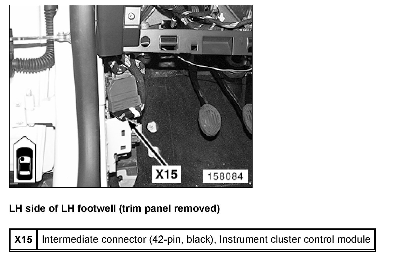
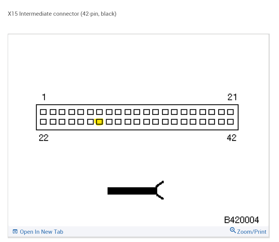
I'll take a look, what did you use to clean the connector.? Was X15 full of corrosion?
It's possible that the corrosion went down into the wiring under the insulation, it does that eventually, the corrosion just keeps growing and will just get into everything
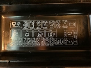
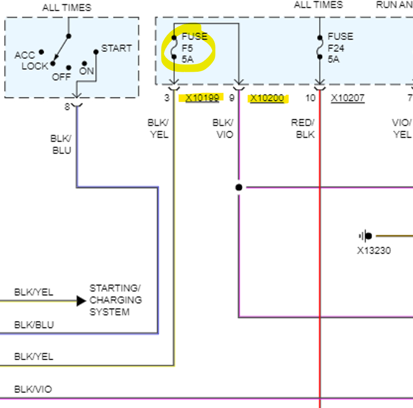
Was it F5 or FL5?
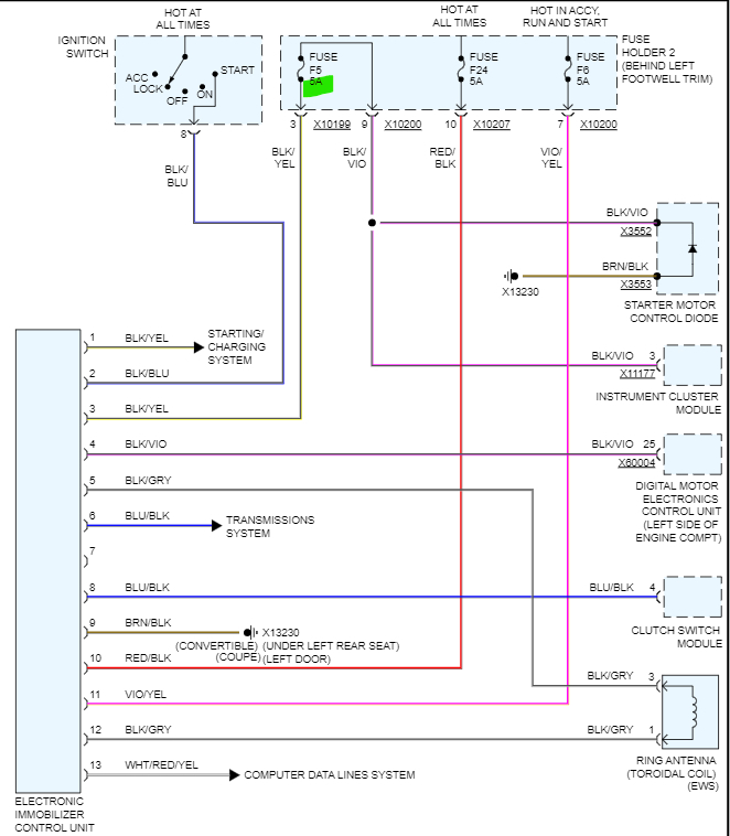
Fuse F5 5amp goes to the Instrument Cluster, only hot with key On
Ok F5 goes from the Immobilizer unit to that Fuse panel then to the Starter Motor diode and also to the instrument cluster.
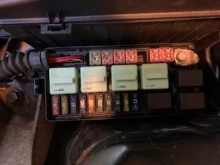
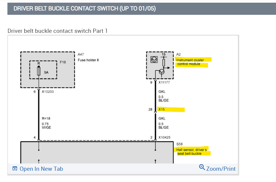
We have to find out how corroded the fuse panel is and x15. It's obviously really bad, my guess is if you were cleaning it with the spray, the corrosion either got farther into x15 or into the fuse panel. The problem is they solder those fuse panels together in layers most of the time, and if you can't get the plastic housing off of it to inspect the damage, there's no way of knowing how much is in there. With no power at F5 the car may not even start now, since it's part of the security system.

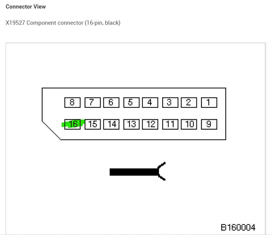
Are you able to check that no pins on any connectors going to the fuse panel or the x15 connector got spread apart while cleaning? With pins that are heavily corroded and have been for some time, the pins become weak and sometimes even break right off because they have been like that for so long, If you think about it like rust for an example, rust causes metal to pretty much disintegrate. It's the same with gangrene and the white crusty corrosion that happens in vehicles, it's all the more worse with a vehicle that has a water intrusion issue. This could have been like this for years, and its just now starting to fall apart because you're doing something about it. This car would have become a no start shortly regardless, At least you know where the issue is. Some people replace computers and modules over issues like this. and they never fix the car. If you end up replacing the fuse panel and a few connectors, that's a lot better than a $2,000 dollar computer, by far.
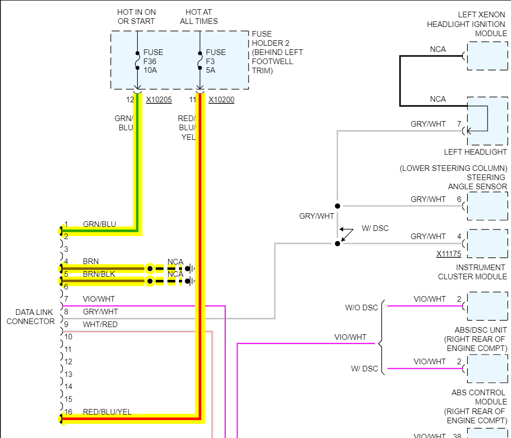
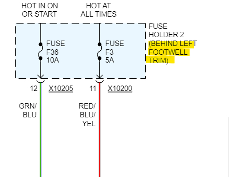
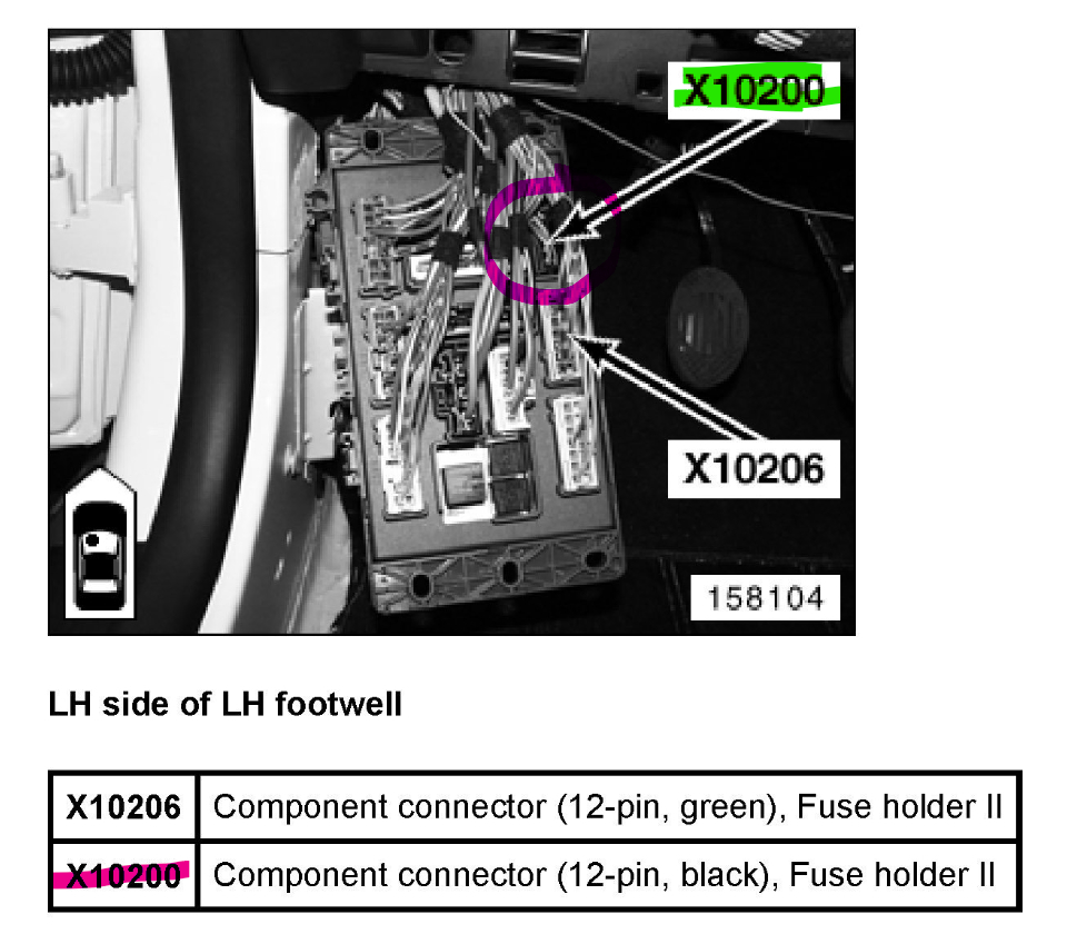
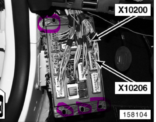
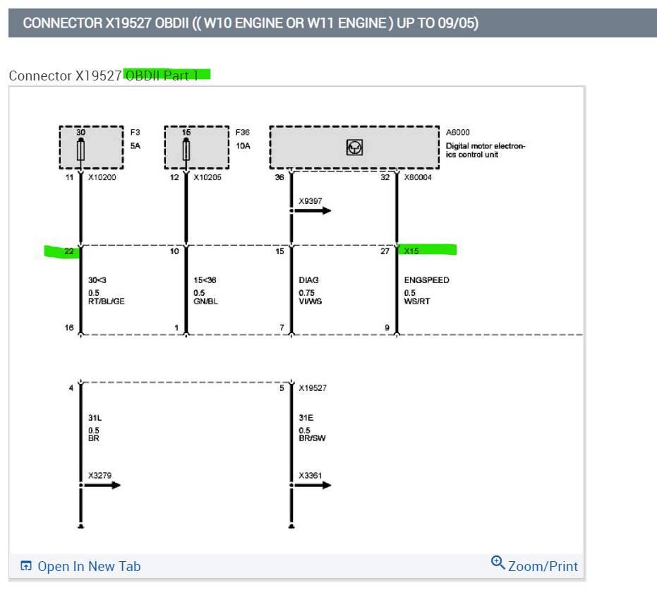
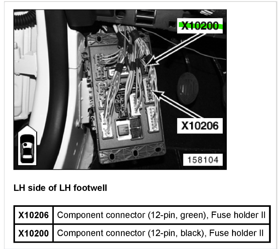
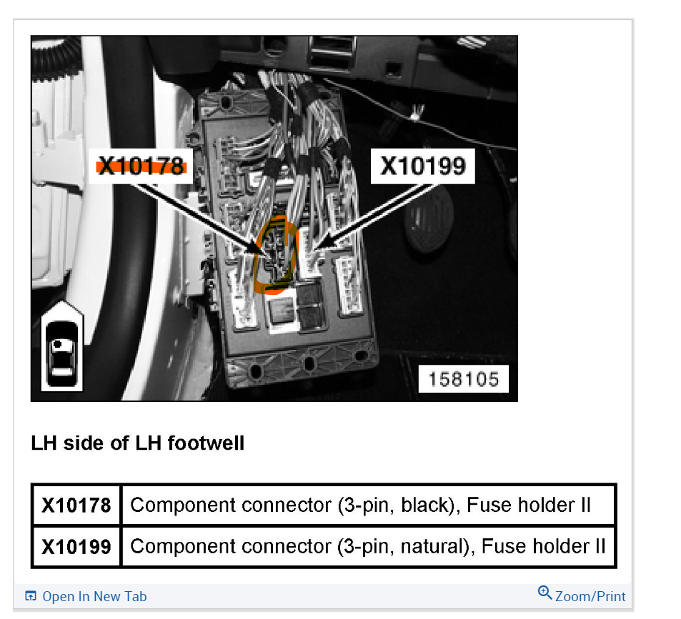
Below is the X10199 comes from the Immobilizer Unit to Fuse F5 and goes back out to the Instrument Cluster on this connector X10200.

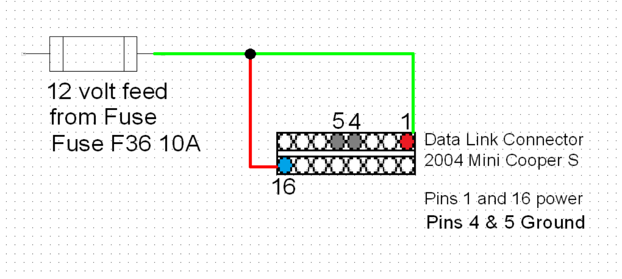
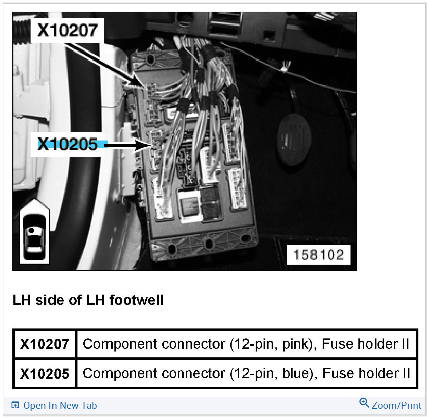
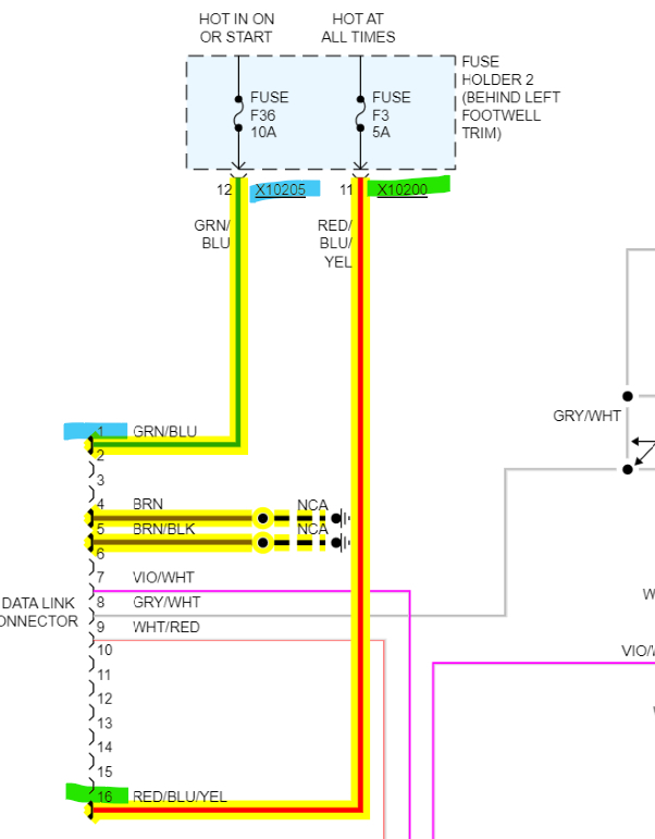
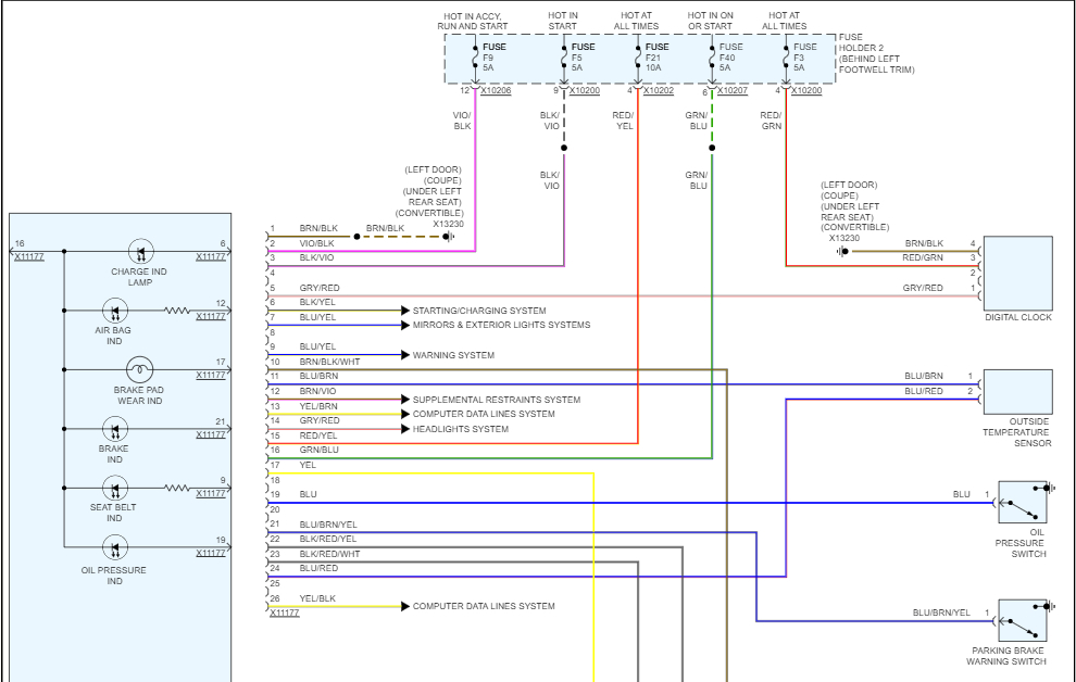
Also 5th diagram X10205 is for Fuse 36, pin 1 of the DLC
And the X10200 is also for Fuse 3, pin 16 of the DLC.

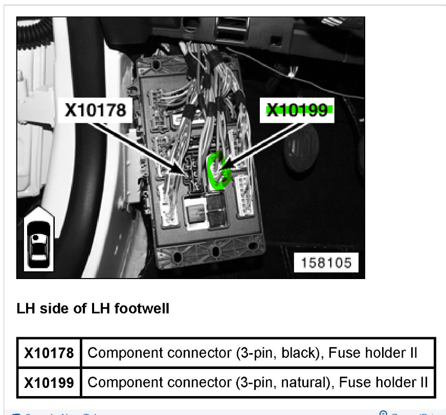
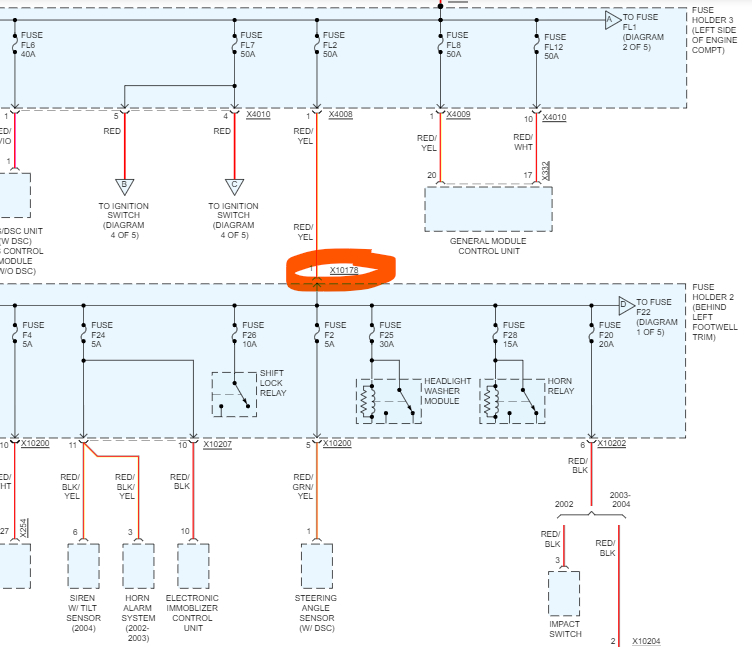
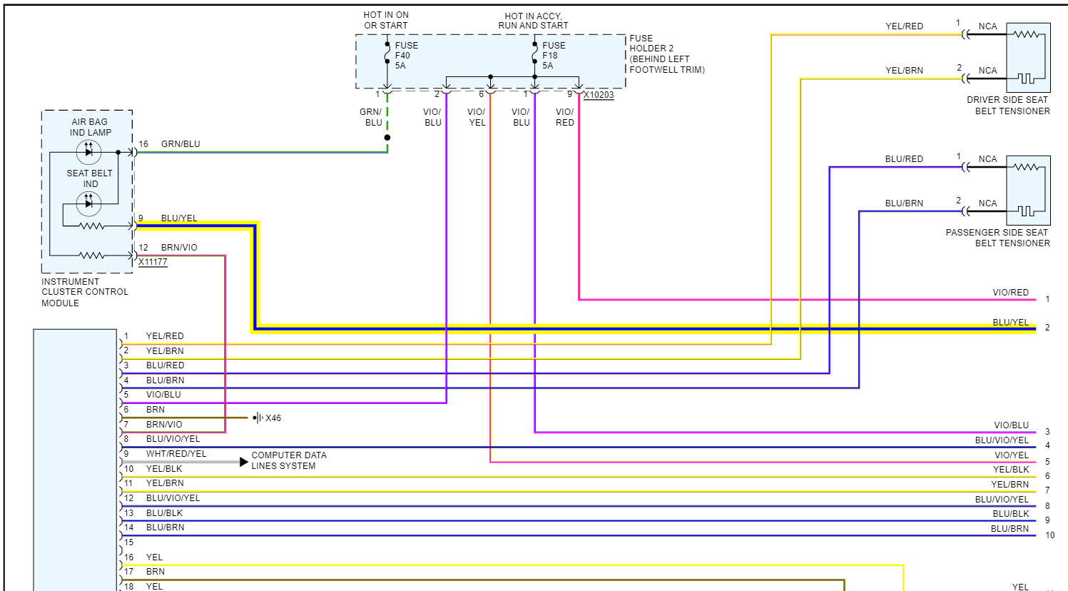
Last one, last 2 diagrams, that connector X10178, pin number 1 on that connector feeds power to that whole fuse panel on a Red/Yellow wire, it will be a higher gauge wire because its powering up so many components. The Red/Yellow wire comes from the Fuse Panel in the engine compartment from Fuse FL2 50amp.
Aug 10, 2022 at 1:16 PM
Avatar
DAVE02903
  • MEMBER
  • 19 POSTS
Good morning,

Thanks for the pictures and the information regarding fuse F5. Yes there was corrosion in x15 which I cleaned with a spray. Looking back in x15 it looks like one of the pins broke off. I have been looking for a salvage yard that may have a Mini but none in this area. I may have to try and get a new one, but not sure exactly what I need.

I will take the fuse box off again and check the connections you high lighted in the picture and make sure nothing has broken or spread from the cleaning. Am I right to assume that even if the x15 pin is broken I should still get power on the F5 fuse with the key on?

If you have any ideas where I can pick up a x15 replacement online that would be appreciated. The pin that was broken seems to be for the tachometer because it was no longer lighting up. That shouldn't have any effect on the F5 getting not getting power correct?

Thanks again for all your help.
Dave
Aug 11, 2022 at 6:17 AM
Avatar
AL514
  • CERTIFIED EXPERT
  • 5,465 POSTS
Below is the F5's entire circuit, it comes from the Immobilizer into the Fuse Holder 2(Fuse F5) then just goes right back out to the Instrument Cluster. For some reason F5 is missing from the aftermarket power diagram altogether, they forget things a lot. But I found it on the Cluster diagram below. Going back and forth through these diagrams, the OEM and aftermarket ones for this specific car are very difficult to read.
But only for F5 right now, you can see in the first diagram it comes in on X10199 and goes right out X10200.
It even shows you the wire color it should be, so black wire with yellow stripe (x10199) and then a Black wire w Violet stripe (x10200). So, you could find those specific wires on those connectors and check them for power. That will tell you if the power is being lost in the Fuse panel (Fuse Holder 2) or if the power is not even getting to the fuse panel.

I've been trying to find a pinout of X15 for hours and just can't seem to, if you can ID the pin that broke and the two wires in connects together, if this was my car, I'd just bypass the connector, but you have to be used to doing electrical work on vehicles. I mean it's only a connector and it's full of corrosion. I would cut the two wires and crimp them together with a heat shrink connector and be done with it. Just do one at a time so you don't get mixed up.

I'm not sure you'll be able to find one of those connectors, maybe a dealership, or like you said a used parts lot. I'm not sure how many you have in your area. Now that a pin is broken, it has to be fixed, but our main concern is getting you through inspection first. They will probably fail you if there's no Tach lighting.

So far I've found that X15 is for the Instrument Cluster control module, but they don't give any information on it.
For the Cluster (diagrams 4 and 5) you can see they don't give us barely anything. It shows the connector and wires to it but doesn't show anything about the Cluster at all. There's no Tach listed, so I couldn't even tell you which wire it was on.

So, it really just depends on what you want to fix first, let's concentrate on one area to get repaired, then we'll move on, instead of jumping around.
Aug 11, 2022 at 11:16 AM
Avatar
DAVE02903
  • MEMBER
  • 19 POSTS
Good morning,

I have made some progress. I have my tachometer working again by doing a work around on the x15. The car starts up and runs. I noticed on that diagram you sent that fuse F5 is only hot on start. Does that mean it will only register on the meter when the car is running or trying to start?

I'm getting ready to do the bypass on the OBD, but before I started, I did a quick check to see if all the lights and blinkers work. All the blinkers work but the driver's side parking light is not on as well as the backside running light, I think it is called. The back taillight does work. I switched bulbs from the passenger side, and they were still not lighting up. The bulb from the driver's side worked on the passenger's side. I'm not sure where to look for the issue and thought it was odd that the blinker works but it doesn't light up like the passenger's side does. Any suggestions? I can't tell what fuse is for the parking light drivers' side. I think it would be the same fuse for both parking lights but I'm not sure maybe they have a driver's side and a passenger side separate. Let me know what you think.

Thanks,
Dave
Aug 13, 2022 at 8:03 AM
Avatar
AL514
  • CERTIFIED EXPERT
  • 5,465 POSTS
Okay, were you able to make a good strong connection for Tach light circuit, when you crimp a wire after you strip the end insolation off, the crimp has to be as tight as you can get it. If you can pull it apart with your hands, it's no good. A rule of thumb to go by. And using the heat shrink connectors will keep any moisture out forever, you can get away with using a lighter to heat the shrink on the connector but be easy about it. You don't want to burn it; I use a small light Butane torch to just barely heat the connector up. Glad you were able to figure that out.
So on to the next, we will call them marker lamps to stay on the same page. Do you have both front and rear on the right side out?
On the left (driver side) you have your 1. Turn signal front, 2. Front Auxiliary Flasher Light (another blinker) 3. Side marker light, 4. Rear side marker light 5. Parking light. and then in the rear there is the Left Taillight assembly which has 4 lamps in it, Parking Light-Turn-Brake-Fog Lights. I'll put up the diagram of them all below.
So, if the problem is isolated to the Left side, since there are so many bulbs, if you can tell me the wiring color for the bulb socket that is out, it will make it easier to identify which one is not powering up. That Taillight Assembly is all housed together and uses one shared Ground wire coming out. Unfortunately, every single bulb has its own single wire coming from a General Module Control Unit as far as I can tell, I haven't looked at the OEM diagrams yet because for this vehicle they break them all up into small sections and they're very difficult to trace out. The General module is located in the Right Footwell, so it's on the passenger side but in the same place as the fuse panel with the corrosion issue. Hopefully, this is not the windshield leaking and we will find more corrosion on the passenger side. The module has 4 main connectors, some of the connectors look to have a bunch of wires and some only have a few, so pull that panel out like you did on the driver side. We're going to have to look for more corrosion on the passenger side. The diagram below is for all the exterior lights on the driver side except the Head lights, there are no specific fuses for any one lamp, there are only fuses for the module that controls them. We might end up in another huge mess on the passenger side, so I would keep looking into that Fuse panel and see if it comes apart or keep an eye out for a new/used one. I'll look into this module some more and see how it works, I'm a bit worried it might have issues with the connectors on it as well.

on a side note, the Switch Panel and the Turn Signal/Head Light Dimmer Switch that are wired into this General Module Control Unit for the exterior lights both have a fuse that runs into Fuse Holder 2, that's the one on the driver side we've been dealing with.

The General Module also has 2 fuses running into it from Fuse Holder 3 in the engine compartment, just wondering was this an auction car?
Also, can you find a Manufacture Build date on this car, it might be on a tag in the driver side door opening, or under the hood on a tag. It will give a month and year (ie 12/03 or 12/2003 for example) because a lot of these OEM diagrams are listed differently for different build dates.
Aug 13, 2022 at 9:42 AM
Avatar
DAVE02903
  • MEMBER
  • 19 POSTS
It's the small round light directly below the headlight on the driver's side. It has two wires to the light, one brown the other seems to be solid green but it might have a faded color maybe blue I can't tell it really looks just light solid green. I also have fog lights, even smaller round lights below them, but they work. The front driver side marker lamp works, the rear side marker light doesn't. All other lights and blinkers seem to be working.

The date of manufacture is 3/4/2004.

Thanks,
Dave
Aug 13, 2022 at 10:46 AM
Avatar
AL514
  • CERTIFIED EXPERT
  • 5,465 POSTS
Okay, I think these are the ones you have out, that Brown wire is going to be the Ground for all the driver side exterior lamps. But as you can see, there is an error on these diagrams, marked in 'Red'. They labelled two pins 29 and two pins 5. You can check to see if you have any voltage at all on the Green/Violet wire, which will be the feed. If there is something more than zero volts, we have a high resistance issue on that wire, if it reads OL on your meter, we will assume for now it's an open circuit and have to test it at the module pin. I've got each connector on the module already labelled, so for these 2 lamps for example, it will be connector x254 for the Rear lights, And then for the Front Lights, is it possible it's the Low Beam that is out, because according to the diagrams both front Fog lamps have Yellow and Brown wires and the Low Beam has a yellow/green and brown wires.. But at the module we will have to go by wire color somewhat, I don't trust these diagrams completely.

Anything that is out, take a voltage reading to see what type of condition we're dealing with.
Aug 13, 2022 at 11:46 AM
Avatar
DAVE02903
  • MEMBER
  • 19 POSTS
I just wanted to update you and thank you for all your help. Everything is working, even the OBD, and I didn't have to do the workaround. I got a used replacement fuse box on eBay and I ended up cutting out the x15 and just connected the wires directly to one another. Now everything works. Thanks again.
Aug 19, 2022 at 9:00 AM
Avatar
AL514
  • CERTIFIED EXPERT
  • 5,465 POSTS
That's great news. I was wondering how you made out with that. Just make sure to do the water test so you don't end up with the same problem down the road, no pun intended. I see a sunroof option in the wiring diagrams, so if you have one of those, make sure to run the hose over that too, maybe have someone else run the hose so you can watch inside for any water drips coming in, since you know where the problem area is now. Keep that panel off that hides the fuse box and watch up above it for water. There must be a leak for the box to have gotten that bad. Just a precaution. Hope your inspection goes well, you might also think about erasing any stored codes before going and then drive the car for a few days so all the readiness monitors have passed. That way you'll only have to go do inspection one time. I know that was a lot of work on your part, but thanks for letting us know the results.
Aug 19, 2022 at 9:35 AM
Avatar
DAVE02903
  • MEMBER
  • 19 POSTS
Hello again,

My car is doing good. Registered and inspected. I have a couple of issues still. One is the A/C which I'm not going to tackle at the moment. But the one I'm having issues with is the seat belt light stays on and won't go off. When I put the car in reverse it goes off. But when I put it back in first gear it comes back on and stays on. Any ideas?

Dave
Sep 11, 2022 at 4:57 PM
Avatar
AL514
  • CERTIFIED EXPERT
  • 5,465 POSTS
Hello again. yeah, the seat belt light on the Instrument Cluster will come on if the sensor in the seat belt latch is not sending a signal to the Restraint system that it is buckled in. There isn't any other lights on are there, such as the SRS light or Airbag light? The sensor in the driver side seat belt latch is a hall effect sensor. So, it will have a power feed (12volt), a wire going to the Cluster (that's the one you're seeing), a signal wire to the Restraint system and a Ground wire that is under the center console. These systems have seat belt tensioners built into them that will react when in an accident. With the airbag, you have to be careful working on any part of the system.
With all the water intrusion you had I'm not surprised more issues are showing up.
And of course, the power for the seat belt sensor comes from the Fuse panel you just replaced. Fuse F18 5amp. I will try to locate exactly where the sensor harness plug is. Most of them are down on your right side where you latch the seat belt in, you might see 4 wires or a section of harness coming out the bottom of the seat belt latch. I'm guessing it might be missing power as so many other things were. When did this start happening?

Looking at BMWs safety instructions, they insist on having only qualified BMW personal to work on this particular system. And this is something I agree with, if an air bag system is triggered by accident it can cause serious injury. This includes even the Seat belt buckles. They are listed as "Pyrotechnic object danger class T1" Which is one of the highest levels. On some Seat Belt Tensioners there is a small charge in the tensioner that will lock the seat belt in the event of a crash.
They list an Airbag Deactivation switch, but do not say where it is located. The battery needs to be disconnected and isolated as well.
I have seen these go off by accident, and its thousands of dollars to replace the airbags.

They require a Terminal Kit to test the Seat Belt Buckle Switch as well using an Oscilloscope. The kit does not actually buckle the seat belt, it's strictly a testing kit (fifth diagram)
So, this is one I would recommend having possibly the dealership look at, I'm not even sure where they get this 4-pin terminal kit. Thats what is needed for the hall effect sensor buckles.
Sep 12, 2022 at 12:54 PM
Avatar
DAVE02903
  • MEMBER
  • 19 POSTS
The seatbelt light has been on since I removed the x15 connector and connected the wires directly. Maybe I mixed up a wire or two. The colors were very similar on some wires. The Air Bag light comes on, does it check and goes off when I start the car so that appears to be working as it should. The scanner for a Mini does detect any error code for the Airbags and multi restraint system. So, I'm not sure what the issue may be.

Thanks for the pictures.

Dave
Sep 12, 2022 at 2:08 PM
Avatar
AL514
  • CERTIFIED EXPERT
  • 5,465 POSTS
The sensor is probably missing its 12v feed, I can look into what connector it's on, and if it is part of the X1 I'd be okay with you fixing that, since you've already been in there. My only worry is the signal wire for the belt buckle goes directly into the SRS system, and a voltage spike into it would not be a good thing at all but give me a few minutes and I'll take a look.

Ok, you were correct, it looks like you might have hooked the wrong wires up on that connector, which is x15, not x1. But I finally found the issue,, I think you may have just hooked a power wire directly to the seat belt light wire.
The diagrams below 1 to 4 are the power wires going to the seat belt sensor and are the power (12v) to the sensor.

But the wire that goes from the seat belt sensor to the Instrument cluster light does go through x15 connector, (diagram 5) is the oem diagram and shows x15. Diagrams 6 is the pinout for the x15 connector,
So you may have it hooked up to another wire, but if you look at diagram 7 the aftermarket diagram label the wire as Blue/Yellow.
The oem diagram looks like it has the wire to the Cluster as colored Blue/Green. And I know after awhile the wire colors can be very difficult to see correctly,, they fade and can be misleading.

Im not sure I would go cutting any wires yet, but take a look at the x15 connector and that pin 28, it should be Blue/Green going in and coming out. If its the incorrect and wired wrong, thats the aftermarket wiring diagrams fault.

I run into this alot, miscolored wires can cause all kinds of issues, like we have here. But thats what is happening. You didnt cut anything with the connector in the 1st diagram, so I think its only the wire going to the light on the dash that might be wired wrong.
Sep 12, 2022 at 3:17 PM
Avatar
DAVE02903
  • MEMBER
  • 19 POSTS
It ended up being the blue, yellow wire. There were two sets that looked identical to me. I just switched them, and the seat belt light came on and when I attached the seat belt it went off as it should. Success! thanks. Everything now seems to be working except the oil light in the cluster. It doesn't come on when I turn the key on. It's probably the same issue two wires with similar colors switched. Any idea what color wire is for the oil light through the x15? This should be my last wiring issue.

Dave
Sep 14, 2022 at 10:10 AM
Avatar
AL514
  • CERTIFIED EXPERT
  • 5,465 POSTS
Yeah, that's a bummer that even the OEM were not exactly correct, yes ill see what color the oil pressure sending unit is to the cluster.
Both diagrams state it's a solid blue wire. It does of course run through x15 and then up into the center of the dash and around then back over to the cluster. The second picture is the location of the oil pressure switch. You have to remove the right front tire (passenger side) to get access to it. But it looks like a solid blue wire all the way from the sensor.
Sep 14, 2022 at 11:25 AM
Avatar
DAVE02903
  • MEMBER
  • 19 POSTS
There is only one solid blue wire, so I have that connected correctly. I guess I could have crimped it incorrectly so I may redo it to make sure. How can I check the wiring from the oil pressure sensor? If I remove the wire connected to the sensor, should I see be able to see some voltage on the connector or maybe resistance if I put a meter across the two wires in the connector? It may be the sensor itself, but I would like to verify the wiring before trying to change that.

Thanks for your assistance.
Sep 15, 2022 at 5:43 AM
Avatar
AL514
  • CERTIFIED EXPERT
  • 5,465 POSTS
There is no definition on exact operation of this specific oil pressure switch, but it provides the ground connection for the oil pressure led in the Instrument Cluster. The power for that led comes through the cluster and when the engine is started, the oil pressure switch either opens the circuit to turn the led off, or it pulls the circuit to ground to shut the light off.

So, what you could try is since you're going to recrimp it anyway, either unplug the sensor or cut the wire and see if the oil pressure light goes out. If it does, then that's what the pressure switch is doing, it would be a normally closed circuit and oil pressure opens the circuit turning the led off. It might be more practical to unplug the sensor behind the passenger side wheel. It's a 1 wire sensor running into the engine block and the wire is Blue there too. But that's up to you.

On one diagram it looks like it's a pull-down circuit and on another it looks like a pull up design. But I know it definitely makes ground for the light on the dash.
There might be another circuit coming off the led going to the engine computer. But in that case the car would usually not start. Most are designed so that if there's no oil pressure the vehicle won't start.
But I would check your crimp first, Ill track down the rest of the connectors for the sensor. There's one in the engine compartment.

You can check either half of the blue wire for voltage, checking voltage won't hurt anything. Because it's a led in the circuit I don't think you're going to see voltage, a led is a diode and diodes only let voltage go one direction,
If you're checking the resistance of a circuit, it is when the multimeter puts out a small amount of current to check resistance, but everything needs to be unplugged to do that or you will end up reading the resistance of the entire circuit. And for example, with an airbag circuit, a multimeter can actually set off an airbag. So do a voltage check if you want to, but I would just check the crimp, see if the light goes out. And I'll get the rest of the connections for it.
Sep 15, 2022 at 2:32 PM
Avatar
DAVE02903
  • MEMBER
  • 19 POSTS
So, the wiring was fine. It was a bad oil pressure switch. I installed a new one and it's working fine now. Next project will be the A/C, but I am going to take a little break before tackling it.

Thanks for your help.
Sep 16, 2022 at 11:03 AM
Avatar
AL514
  • CERTIFIED EXPERT
  • 5,465 POSTS
Yeah, glad you got most things straightened out. I'm surprised at how much work that car needs. Hopefully you have heat at least.
Sep 16, 2022 at 1:22 PM