Good morning again,
What problems were created by revving to 5,000?
The codes 131 and 300 are not from his high RPM push. That does not damage anything.
I do not understand the battery voltage? You said it is 12.9 this morning. Was that running or with the engine off?
How do you think the battery was damaged? What was damaged?
The 300 is a misfire code. It could be related to plugs and wires. It could also be from low fuel pressure which is most common.
https://www.2carpros.com/articles/engine-misfires-or-runs-rough
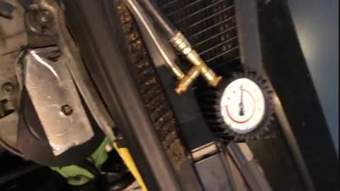
https://www.2carpros.com/articles/how-to-check-fuel-system-pressure-and-regulator
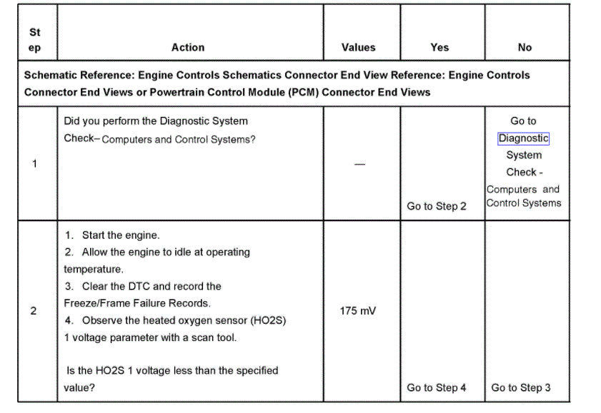
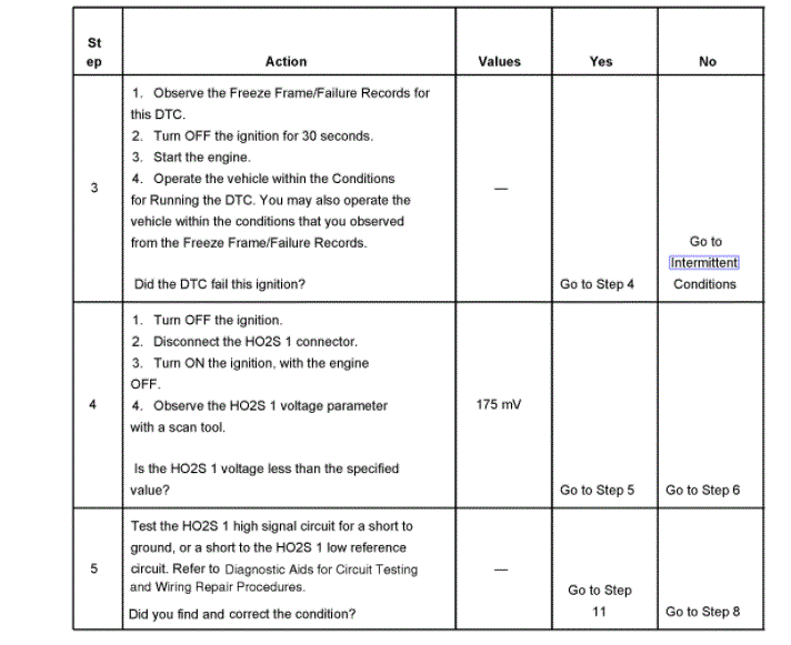
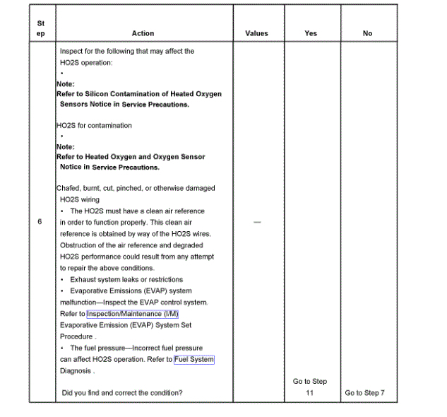
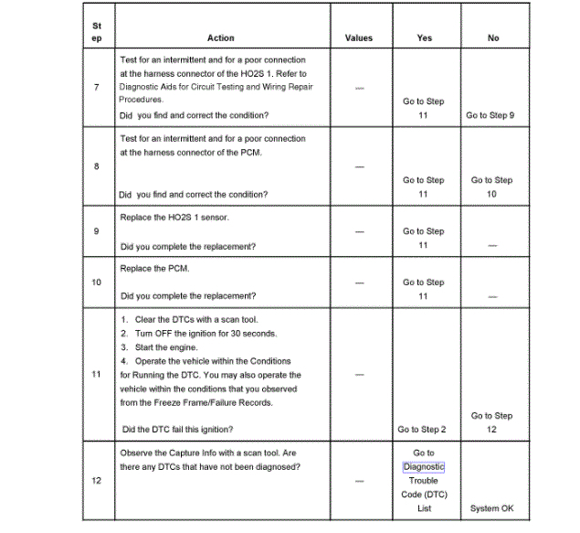
The 131 is for an O2 sensor heater circuit. I posted below about the code and attached the flow chart for you.
https://www.2carpros.com/articles/how-an-oxygen-sensor-works
https://www.2carpros.com/articles/how-to-test-an-oxygen-sensor-02-sensor
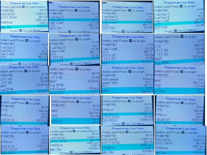
The one reading I would like to see is the long term trim reading for the O2 sensor.
Roy
CIRCUIT DESCRIPTION
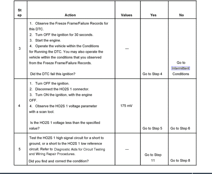
Heated oxygen sensors (HO2S) are used for fuel control and post catalyst monitoring. Each HO2S compares the oxygen content of the surrounding air with the oxygen content of the exhaust stream. When the vehicle is first started, the power-train control module (PCM) operates in an Open Loop mode, ignoring the HO2S signal voltage when calculating the air-to-fuel ratio. The PCM supplies the HO2S with a reference, or bias, voltage of about 450 mV. The HO2S generates a voltage within a range of 0-1,000 mV that fluctuates above and below bias voltage once in Closed Loop. A high HO2S voltage output indicates a rich fuel mixture. A low HO2S voltage output indicates a lean mixture. Heating elements inside the HO2S minimize the time required for the sensors to reach operating temperature, and to provide an accurate voltage signal. If the PCM detects that the HO2S 1 voltage remains below a calibrated amount for an excessive amount of time, DTC P0131 will set.
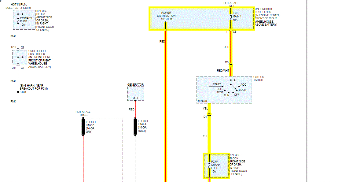
Each HO2S 1 has the following circuits:
A HO2S 1 high signal circuit
A HO2S 1 low reference circuit
A HO2S 1 heater ignition voltage circuit
A HO2S 1 heater low control circuit
A low reference loop circuit
CONDITIONS FOR RUNNING THE DTC
DTCs P0101, P0102, P0103, P0107, P0108, P0112, P0113, P0116, P0117, P0118, P0121, P0122, P0123, P0125, P0128, P0410, P0440, P0442, P0443, P0446, P0449, P1441 are not set.
The Air Fuel Ratio parameter is between 12:1-16.5:1.
The TP sensor parameter is between 3-35 percent.
The system voltage is between 9-18 volts.
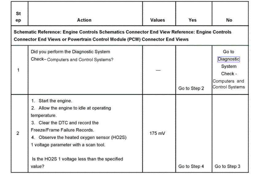
CONDITIONS FOR SETTING THE DTC
The PCM detects that the HO2S 1 voltage is less than 140 mV for more than 30 seconds.
OR
The PCM detects that the HO2S 1 voltage is less than 600 mV during power enrichment (PE) mode for more than 10 seconds.
ACTION TAKEN WHEN THE DTC SETS
The control module illuminates the malfunction indicator lamp (MIL) on the second consecutive ignition cycle that the diagnostic runs and fails.
The control module records the operating conditions at the time the diagnostic fails. The first time the diagnostic fails, the control module stores this information in the Failure Records. If the diagnostic reports a failure on the second consecutive ignition cycle, the control module records the operating conditions at the time of the failure. The control module writes the operating conditions to the Freeze Frame and updates the Failure Records.
CONDITIONS FOR CLEARING THE MIL/DTC
The control module turns OFF the malfunction indicator lamp (MIL) after 3 consecutive ignition cycles that the diagnostic runs and does not fail.
A current DTC, Last Test Failed, clears when the diagnostic runs and passes.
A history DTC clears after 40 consecutive warm-up cycles, if no failures are reported by this or any other emission related diagnostic.
C lear the MIL and the DTC with a scan tool.
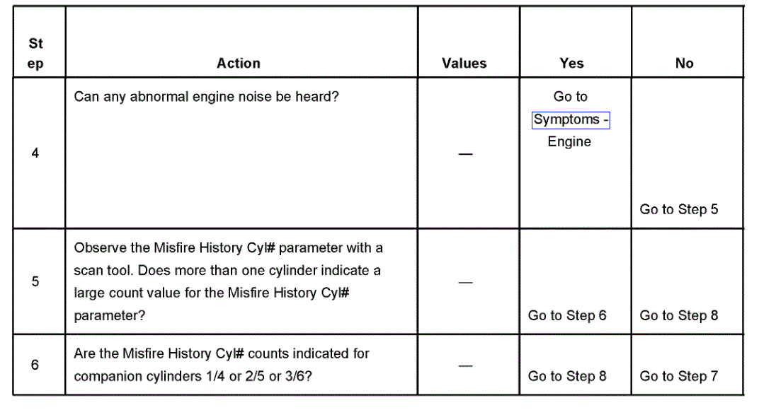
300
SYSTEM DESCRIPTION
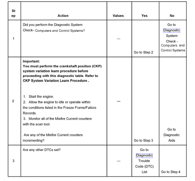
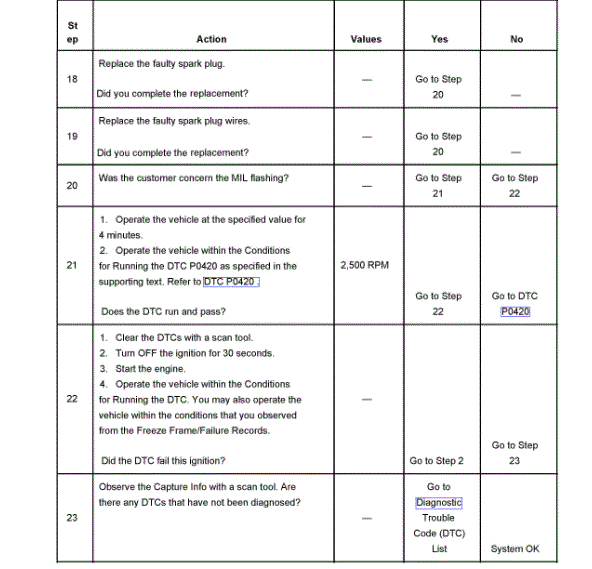
The power-train control module (PCM) uses information from the ignition control (IC) module and the camshaft position (CMP) sensor in order to determine when an engine misfire is occurring. By monitoring variations in the crankshaft rotation speed for each cylinder, the PCM is able to detect individual misfire events. A misfire rate that is high enough can cause the 3-way catalytic converter (TWC) to overheat under certain driving conditions. The malfunction indicator lamp (MIL) will flash ON and OFF when the conditions for TWC overheating are present. If the PCM detects a misfire rate sufficient to cause emission levels to exceed mandated standards, DTC P0300 will set.
CONDITIONS FOR RUNNING THE DTC
DTCs P0101, P0102, P0103, P0107, P0108, P0116, P0117, P0118, P0121, P0122, P0123, P0125, P0128, P0336, P0341, P0502, P0503, P1106, P1107, P1114, P1115, P1121, P1122, P1336, P1351, P1352, P1361, P1362, P1374 are not set.
The engine speed is between 525-5,900 RPM.
The ignition voltage is between 9-18 volts.
The engine coolant temperature (ECT) is between -7 and +125°C (21-255°F).
The fuel level is more than 10 percent.
The throttle position (TP) sensor angle is steady within 1 percent.
The antilock brake system (ABS) and the traction control system are not active.
The transmission is not changing gears.
The A/C clutch is not changing states.
The PCM is not in fuel shut-off or decel fuel cut-off mode.
The PCM is not receiving a rough road signal.
CONDITIONS FOR SETTING THE DTC
The PCM is detecting a crankshaft rotation speed variation indicating a misfire sufficient to cause emission levels to exceed mandated standards.
ACTION TAKEN WHEN THE DTC SETS
The control module illuminates the malfunction indicator lamp (MIL) on the second consecutive ignition cycle that the diagnostic runs and fails.
The control module records the operating conditions at the time the diagnostic fails. The first time the diagnostic fails, the control module stores this information in the Failure Records. If the diagnostic reports a failure on the second consecutive ignition cycle, the control module records the operating conditions at the time of the failure. The control module writes the operating conditions to the Freeze Frame and updates the Failure Records.
CONDITIONS FOR CLEARING THE MIL/DTC
The control module turns OFF the malfunction indicator lamp (MIL) after 3 consecutive ignition cycles that the diagnostic runs and does not fail.
A current DTC, Last Test Failed, clears when the diagnostic runs and passes.
A history DTC clears after 40 consecutive warm-up cycles, if no failures are reported by this or any other emission related diagnostic.
Clear the MIL and the DTC with a scan tool.
DIAGNOSTIC AIDS
Excessive vibration from sources other than the engine could cause DTC P0300 to set. The following are possible sources of vibration:
Variable thickness brake rotors-Refer to Symptoms - Hydraulic Brakes in Hydraulic Brakes. See: Hydraulic System, Brakes > Symptom Related Diagnostic Procedures
Worn or damaged accessory drive belt-Refer to Symptoms in Engine. See: Engine > Symptom Related Diagnostic Procedures
Spray water on the secondary ignition components using a spray bottle. Look and listen for arcing or misfiring.
Images (Click to enlarge)
Aug 19, 2020 at 4:05 AM