No start condition, p0118 and p0343 codes

2003 CADILLAC CTS
168,000 MILES • 3.2L • 6 CYL • 2WD • AUTOMATIC
Avatar
RGRUBER69
  • MEMBER
  • 22 POSTS
Replaced thermostat, coolant temperature sensor. Took for test drive and ran good, came home and checked coolant, filled some more. When looking a saw the cam sensor wires were taped together. I jiggled them and the car stalled. Wouldn't start after. Replace cam position sensor, reset ECM and the car started, but was hard to start. I drove about 5 minutes and came home. it was rough at first until warmed up then ran fine. Turned it off at home, now will not start. Cranks but doesn't fire. Checked codes, under pending I have p0118 coolant temperature sensor high circuit and p0343 cam position sensor high circuit. Live data on my little scanner shows -40 on the coolant sensor. Checked all wires, nothing pinched or broken that I can see. Now I'm stumped and frustrated. Please help!
Apr 14, 2020 at 6:34 PM
Advertisement
Avatar
KASEKENNY
  • CERTIFIED EXPERT
  • 18,907 POSTS
Have you repaired the wires that were taped? The -40 is an indication that you have an open circuit. That is a default when either the sensor is open or the wiring to the control module. I attached the testing for the ECT code. Pay close attention on step 6 assuming you don't repair it in a prior step. However, I suspect you have a 5 volt reference issue.

I also included the Cam code but I would start with the ECT temperature code and see what you find. I included the wiring diagram as well. As you will see the cam sensor and ECT share a low reference wire which is spliced together. That is the 5 volt reference wire which I suspect is your issue.

Let me know and we can go from there. Thanks
Apr 14, 2020 at 7:04 PM
Avatar
JACOBANDNICKOLAS
  • CERTIFIED EXPERT
  • 110,175 POSTS
Hi,

The coolant temperature sensor is the likely cause of the no start. If it is indicating -40° F, it's dumping fuel to the engine to run in extreme cold temperatures.

Now, anytime I have had this happen, the sensor was bad. However, you indicated the sensor was replaced. So, we need to check it to determine if the sensor is bad or there is excessive resistance in the wiring to it, or the plug itself.

If you look at the attached pic, it shows what the resistance should be based on temp. Before going crazy and testing it, reconfirm there is no wiring damage and the connector is tight, clean, and there is no damage to the connector.

https://www.2carpros.com/articles/how-to-use-a-voltmeter


Also, just to confirm we are referring to the same part, it is located in the crossover pipe. See pic 2

Because of the sensor's location, I hate to say it, but it will be easier to remove it for checking unless you can access it to check resistance.

The only other thing I'm concerned about is the connection at the cam sensor. You indicated it was taped. Make sure that everything is properly put back together and shielded.

To shed some light on my rational for the not running condition is simple. You have two codes. From experience, I know if the ECT is indicating -40, either the engine will not start or be running extremely rich if the ambient temp isn't as indicated. If you pull a plug after trying to start it, chances are it will be wet with fuel. Now as far as the cam sensor code, the reason I don't feel that is causing a no start condition is because the system is designed to still run in a default mode even if the crank sensor fails. The only thing that will cause a no start related to the cam sensor would be if there was no crankshaft position sensor signal. Then it wouldn't run. An easy way to check for a crank signal is simple. Using your live data scanner, see if there is an RPM signal when cranking the engine. If there isn't one, chances are the crankshaft position sensor has failed. If you can't read an RPM signal, check to see if there is spark to the plugs.

Here is a link that shows how to check for spark:

https://www.2carpros.com/articles/how-to-test-an-ignition-system

________________________________________________

Okay, I hope this all makes sense. Let me know what you find or if you have other questions. I'll be here.

Take care,
Joe


Apr 14, 2020 at 7:14 PM
Advertisement
Avatar
RGRUBER69
  • MEMBER
  • 22 POSTS
Kasekenny, with both sensors sharing a common ref wire, can I assume that there should be continuity between the two? And are those the only two sensors to share that common wire? And on the sensor wires, should I check for 5v on the tan wire? Before treating into the entire wire harness, I'd like to isolate smaller sections to check!
Jacobandnickolas, I did replace the cam sensor that had the taped wires, but an currently trying to chase the remaining wires for damage. I'm hoping it didn't short the ECM! As far as my little scanner, it shows approx 750 rpm's at cranking, so I'm assuming crankshaft sensor is okay!
Apr 15, 2020 at 4:54 AM
Avatar
KASEKENNY
  • CERTIFIED EXPERT
  • 18,907 POSTS
Yes. They will have continuity but you want to check end to end. Meaning from the module to the component. Clearly when there is a splice you will have continuity from the module to multiple sensors.

If you have 5 volts coming out of the module, you can just run a new wire to each sensor. In essence you splice in a new wire and run it directly to the sensor and replace the wire that is at the sensor. Due to this being a splice for multiple sensors you don't want to eliminate the current wiring or you will lose the 5 volt reference to the other sensors. You just want to replace the wires that have the issue. This way you don't need to do an entire harness. Does that make sense?
Apr 15, 2020 at 7:48 AM
Avatar
RGRUBER69
  • MEMBER
  • 22 POSTS
Kasekenny1, let me see if I follow you! If my ECM is putting out 5v, I can tap into that wire at the ECM and run new to each sensor affected. Since there's only 2 sensors affected, I would cut the tan wire at each sensor harness and run a new wire from ECM to each sensor harness. That would leave me with 2 splice points, the original s111 to all other sensors, and the new splice point I created for the affected sensors.
How many sensors actually share that same tan wire? Coolant and cam for sure, I'm thinking also MAF and IAT sensors as well.
And thank you, some very helpful knowledge being passed along!
Apr 15, 2020 at 9:53 AM
Avatar
RGRUBER69
  • MEMBER
  • 22 POSTS
Okay, so now I'm more confused. My yellow wire on the coolant sensor has 5v, my pink/black (which I've read is the low ref up to the s111 splice) wire on cam sensor has 5v. Tan wire on coolant has nothing and tan on cam has 12v. When coolant sensor unplugged, I get nothing on the cam pink/black wire. I found the 5v wire from the ECM. Oh boy.. Lol
Apr 15, 2020 at 4:23 PM
Avatar
RGRUBER69
  • MEMBER
  • 22 POSTS
And, to be honest, the pink wire referenced is actually brown/black on my harness!
Apr 15, 2020 at 4:56 PM
Avatar
RGRUBER69
  • MEMBER
  • 22 POSTS
Now I'm really not sure what happened, I was double checking voltage at the cam sensor, and all the sudden it was reading 10v! When I unplugged the MAF sensor harness it dropped to 5v.. I didn't find any other damage to wires, but I haven't yet got behind the drivers side head to undo the wire loom back there. It's confusing me that I'm getting 5v on each harness, just not on the wires they would be, and then suddenly jumped to 10v.... Is that a sign of bad computer? Anyway I feel more confused now!
Apr 15, 2020 at 5:39 PM
Avatar
KASEKENNY
  • CERTIFIED EXPERT
  • 18,907 POSTS
I need to stop using the aftermarket diagrams because they are a little misleading on these types of issues. You understand me correctly but I am wondering exactly where you found 12 volts on the tan cam wire. That doesn't sound right.

These diagrams explain what is happening a lot better. The Low Ref wiring is the 5 volt ground back to the ECM. The ECM supplies 5 volts and then supplies the ground for each sensor. Look like the MAF, Cam, and ECT are the only ones on that splice. Since that is the case, I would just create your own splice to each sensor from the ECM pin 26.
Apr 15, 2020 at 5:40 PM
Avatar
RGRUBER69
  • MEMBER
  • 22 POSTS
At the cam harness, I have brown/black wire(pink), brown/white wire and tan wire. 12v at tan, 5v at brown/black(says pink on diagram!). On the coolant sensor, 5v at yellow, nothing on tan... Possibly the 12v is because that wire is shorted?! I've yet to find where, but nothing looks pinched/burnt/damaged, just no room to get my hands on to remove the wire loom!
Those schematics make sense. 5v in, tan wire is like a return. I found the tan wire at ECM, I removed harness at ECM and back probed it checking continuity to all 3 sensors, only got it at MAF sensor. That was my main thing was how many sensors are connected, so tomorrow I will definitely tap into the ECM wire and run new to coolant and cam. I'm trying to learn and this is *just* at the scope of my knowledge on vehicle electrical! And Cadillac's are probably not the wisest thing to learn on, lol.
Apr 15, 2020 at 6:10 PM
Avatar
RGRUBER69
  • MEMBER
  • 22 POSTS
And I will recheck voltage again tomorrow before anything to double and triple check those readings I got tonight.
Apr 15, 2020 at 6:11 PM
Avatar
RGRUBER69
  • MEMBER
  • 22 POSTS
I think that maybe my 'tan' wire at the cam sensor may have been pink and it's just faded. If I'm reading the diagram correct, pk (pink?) from fuse panel would have 12v. Power steering fluid was found in the harness there and I think faded the color of wires.
Anyway, pin 26, new splice from there to coolant, cam, MAF sensor, and looks like maybe knock sensor as well? If I'm reading the schematic right...
That's all for tomorrow though, it's freezing out right now!
Apr 15, 2020 at 6:51 PM
Avatar
RGRUBER69
  • MEMBER
  • 22 POSTS
I'm making good progress! Got new wires ran to sensors, and my live data now shows proper ECT and IAT temp! No pending codes! But I accidentally leaned on the vapor canister Purge valve and busted it, so have to replace before I actually get it all back together to try and start it, but I'm feeling good about it! Thank you very very much for the help and diagrams, and I will report back once it's back together (and running!!).
Apr 16, 2020 at 3:48 PM
Avatar
KASEKENNY
  • CERTIFIED EXPERT
  • 18,907 POSTS
Sorry I didn't get back to you. Yes. That is progress. Based on the fact that you have proper readings means you got it. Thanks for the update. Let us know when it is all back together and you get some miles on it to confirm it but I think you are in good shape.

Also, if this is you just learning then you are far ahead of a lot of mechanics out there. Wiring is one of the hardest things for most mechanics to grasp and you just found and repaired an issue that would confuse some experienced mechanics.

Thanks
Apr 16, 2020 at 5:42 PM
Avatar
RGRUBER69
  • MEMBER
  • 22 POSTS
Couldn't have gotten this far without your help. I can tear down and rebuild engines with my eyes closed, but electrical has never been a strong point of mine.
Just bought this car last week, and kinda wish I had seen the hack job on the cam sensor wires before I bought it! Live and learn though.
Apr 16, 2020 at 7:26 PM
Avatar
JACOBANDNICKOLAS
  • CERTIFIED EXPERT
  • 110,175 POSTS
Glad to hear you got it taken care of. Make sure to come back in the future if you need anything.

Take care,
Joe
Apr 16, 2020 at 7:40 PM
Avatar
RGRUBER69
  • MEMBER
  • 22 POSTS
Okay, got a new problem. Just went to double check everything still good and secure wires. Coolant back to-40, pending codes again... I'm back to square one. the ref wire on my maf sensor is outputting 10v which is pushing through all the other sensor wires. Naturally I unplugged the harness to not damage anything else.... But I have no clue where to go from here. Would a bad maf sensor do that? Should the yellow wire on maf harness supply 5v? I'm not getting anything on that, and I have 12v on the red wire. There are 2 other tan wires on the harness but I'm not sure where they go.
Apr 17, 2020 at 6:39 AM
Avatar
RGRUBER69
  • MEMBER
  • 22 POSTS
I'm thoroughly confused!
Apr 17, 2020 at 6:40 AM
Avatar
RGRUBER69
  • MEMBER
  • 22 POSTS
Left to right, yellow wire had 9.3v when plugged in to maf sensor, 0v when unplugged. Next wire tan has 5v plugged in or not. Middle tan is low ref. Next is red 12v with ignition on. Last wire is tan and has 5v plugged in or not.
Apr 17, 2020 at 7:09 AM
Avatar
RGRUBER69
  • MEMBER
  • 22 POSTS
I'm thinking I've still got a short somewhere. Ref line is still showing 10v with ECM harness connected or removed... I've looked at all my harness up to the rear of the engine, and without pulling the engine is gonna be impossible to check the rest! Is it possible to do the same for the signal lines to the sensors as I did the low ref lines? Run straight from ECM to sensor harness? Do the coolant, MAF and cam signal wires share and splice points?
Apr 17, 2020 at 12:35 PM
Avatar
JACOBANDNICKOLAS
  • CERTIFIED EXPERT
  • 110,175 POSTS
Hi,

If you have a short, then yes, you can run a new line. But, if you have a short to power when you have both ends disconnected, you will need to eliminate that because you will have a hot wire cut at both ends which is shorted to power somewhere in the middle. (Does that make sense?)

Joe
Apr 17, 2020 at 4:49 PM
Avatar
RGRUBER69
  • MEMBER
  • 22 POSTS
Makes perfect sense! If I (and this is a big if) I did go that route and run all new wires from ECM to sensors, I would of course cap all cut wires at the ends. But I do want to do this the right way, electrical has never been my strong suit and I'm trying to wrap my head around how best to verify what wires are shorted. That's so much wire loom and tape to cut through! And so many places I can't get to without disassembling parts of the engine!
Apr 17, 2020 at 5:16 PM
Avatar
RGRUBER69
  • MEMBER
  • 22 POSTS
Makes perfect sense! If I (and this is a big if) I did go that route and run all new wires from ecm to sensors, I would of course cap all cut wires at the ends. But I do want to do this the right way, electrical has never been my strong suit and I'm trying to wrap my head around how best to verify what wires are shorted. That's soooooo much wire loom and tape to cut through! And so many places I can't get to without disassembling parts of the engine!
Apr 17, 2020 at 5:16 PM
Avatar
KASEKENNY
  • CERTIFIED EXPERT
  • 18,907 POSTS
Exactly! I rarely replace harnesses any more or tear them apart. When done right as Joe described it is much easier and cleaner to run a new one and secure it. Let us know how you make out. Thanks
Apr 18, 2020 at 7:01 PM
Avatar
RGRUBER69
  • MEMBER
  • 22 POSTS
I'm no closer to understanding what exactly happened. I've rewired all my sensors from the ECM to the sensors, MAF, coolant, cam, vapor canister, intake.. I'm still getting 10v on my low ref lines when MAF sensor is plugged in, 0v when unplugged and my coolant sensor reading is still at -40 either way. When I first rewired the low reference lines, everything read fine until the next morning when I went out to cleanup the new wires, I double checked my readings and that's what I was getting. At this point I don't know what else to do or check! New sensors, new harnesses, new wires, no change... No more pending codes or stored codes, still no start condition. Help!!!
Apr 25, 2020 at 11:02 AM
Avatar
RGRUBER69
  • MEMBER
  • 22 POSTS
Okay, not sure if this will help or make any sense, but I've ran new 12v wire from fuse panel to my cam sensor. When I disconnect that wire at the fuse panel, I get normal 5v on the low ref. And by coolant temperature reads -14. Weird, and as stated, I'm getting way more confused with everything I do!
Apr 25, 2020 at 4:56 PM
Avatar
JACOBANDNICKOLAS
  • CERTIFIED EXPERT
  • 110,175 POSTS
Hi,

I am getting more confused as well. LOL The sensor should have 12v from the ECM. If I understand, you ran a jumper wire to 12v from a fuse to the cam sensor. Is that when you had closer to the correct voltage from the low reference and the -14° F from the coolant temperature sensor? What is the actual temperature?

Let me know.

Take care,
Joe
Apr 26, 2020 at 7:33 PM
Avatar
RGRUBER69
  • MEMBER
  • 22 POSTS
I cut the 12v wire to cam sensor at the fuse panel, ran a new 12v line. But checked all my readings before hooking up the new wire. That's when I had the -14 and correct voltage at low ref. With No 12v hooked up at cam sensor. Actual temperature was about 65°.
Apr 27, 2020 at 2:01 AM
Avatar
JACOBANDNICKOLAS
  • CERTIFIED EXPERT
  • 110,175 POSTS
If you look at picture 1, it shows where the power supply to the cmp comes from. You replaced that. Next, note that one wire splices (I circled it) to the low ref. That low reference is used by the coolant temp sensor and the MAF sensor. Since you get the same thing when you run power direct but chances when you remove the power to the CMP, something is likely back feeding power to MAF. Disconnect the MAF sensor and see if it changes the reading when you power the CMP.

Let me know.
Joe
Apr 27, 2020 at 11:28 AM
Avatar
RGRUBER69
  • MEMBER
  • 22 POSTS
I've completely removed the splice pack circled and replaced all low ref wires from the ECM to each sensor, creating a new splice at the ECM side. The 12v power to the CMP and MAF have been replaced from the fuse panel harness to the sensors, along with all the other wires in each harness, at the ECM.
Apr 27, 2020 at 12:34 PM
Avatar
JACOBANDNICKOLAS
  • CERTIFIED EXPERT
  • 110,175 POSTS
I am going to ask for another tech's opinion, but in all honesty, I suspect something to be wrong with the ECM.

Lets see what he says.

Joe
Apr 28, 2020 at 7:31 PM
Avatar
STRAILER
  • CERTIFIED EXPERT
  • 53,854 POSTS
Hello,

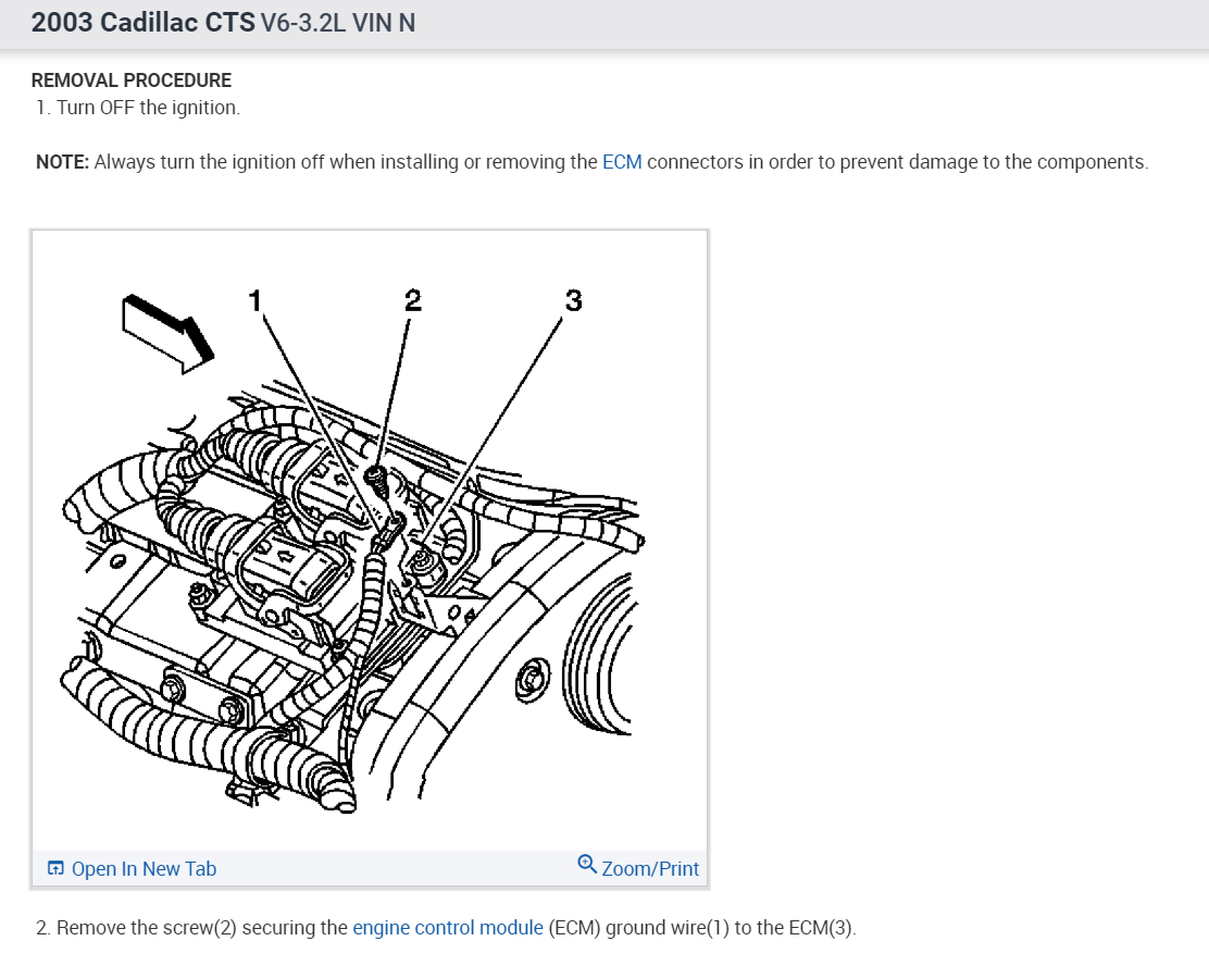
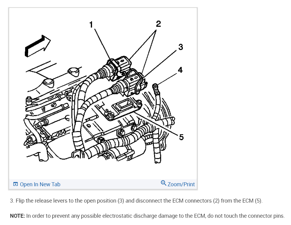
Yes, it sounds like the drivers inside the PCM have gone bad, probably due to the shorted wiring. I would try a rebuild unit please give your VIN number when ordering. Here are the instructions on how to replace the unit in the diagrams below. Yours should have this done before you get it.

Before Programming a Control Module (shop)

IMPORTANT: DO NOT program an existing control module with the identical software/calibration package. This procedure is not a short cut to correct a driveability condition. This is an ineffective repair. A control module should only be programmed when the following occurs:
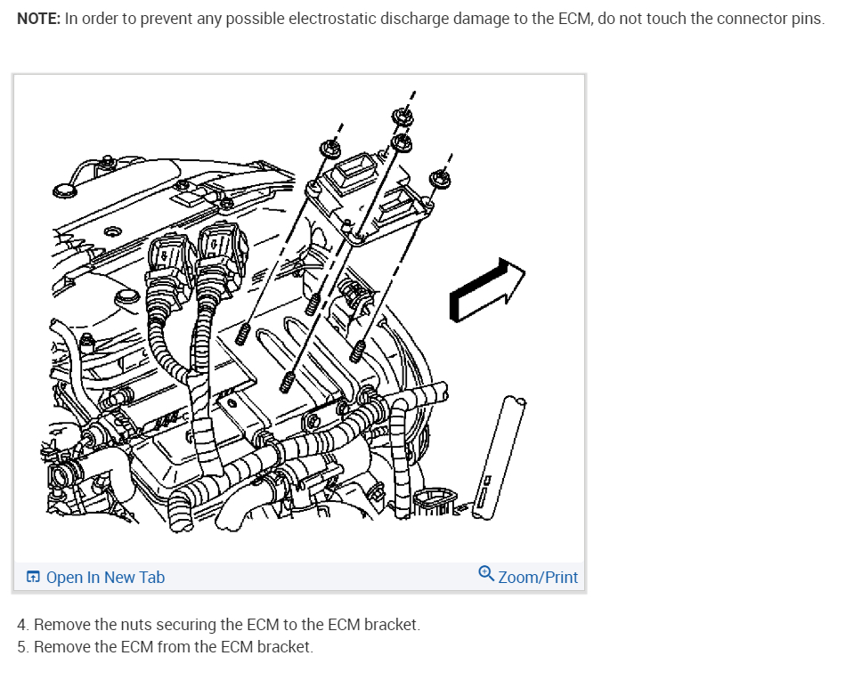
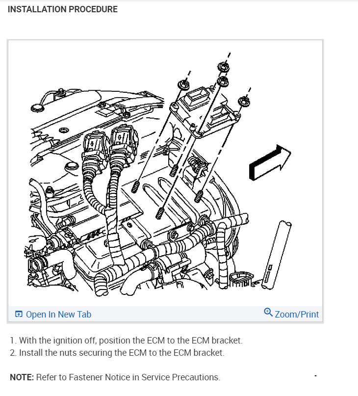
- When a service procedure instructs you to replace the control module. The service part control module does not contain operating software or calibrations.
- General Motors Corporation releases an updated software/calibration package.

Ensure that the following conditions are met before programming a control module:
- Vehicle system voltage:
- There are no charging system concerns. All charging system concerns must be repaired before programming a control module.
- The battery voltage is greater than 12 volts but less than 16 volts. The battery must be fully charged before programming the control module.
- A battery charger is NOT connected to the vehicles battery. Incorrect system voltage or voltage fluctuations from a battery charger may cause programming failure or control module damage.
- Turn OFF or disable any system that may put a load on the vehicles battery. Turn OFF or disable systems such as:
- Daytime running lights (DRL). Applying the parking brake, on most vehicles, disables the DRL system.
- Heating, ventilation, and air conditioning (HVAC) systems
- Cooling System fans, etc.
- The ignition switch is in the proper position. The scan tool prompts you to turn ON the ignition, with the engine OFF. DO NOT change the position of the ignition switch during the programming procedure unless instructed to do so.
- All tool connections are secure:
- The RS-232 cable
- The connection at the DLC
- The voltage supply circuits
- The OBPA
- DO NOT disturb the tool harnesses while programming. If an interruption occurs during the programming procedure, programming failure or control module damage may occur.
- If you are performing the pass-through programming procedure using a notebook computer without the power cord, ensure that the internal battery is fully charged.

After Programming a Control Module
The powertrain may operate slightly different after a control module software/calibration update. Operating the powertrain through various driving conditions allows the control module to re-learn certain values. The control module must re-learn the following after a software/calibration update:
- Fuel trim correction
- Idle air control (IAC) learned position
- Automatic transmission shift adapts

Other learned values only re-learn by performing a service procedure.

If a control module is replaced the following service procedures may need to be performed:
- The crankshaft variation learn procedure
- The engine oil life reset procedure
- The idle learn procedure
- The inspection/maintenance complete system set procedure
- The vehicle theft deterrent password learn procedure
- The throttle position (TP) sensor learn procedure

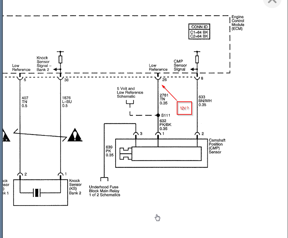
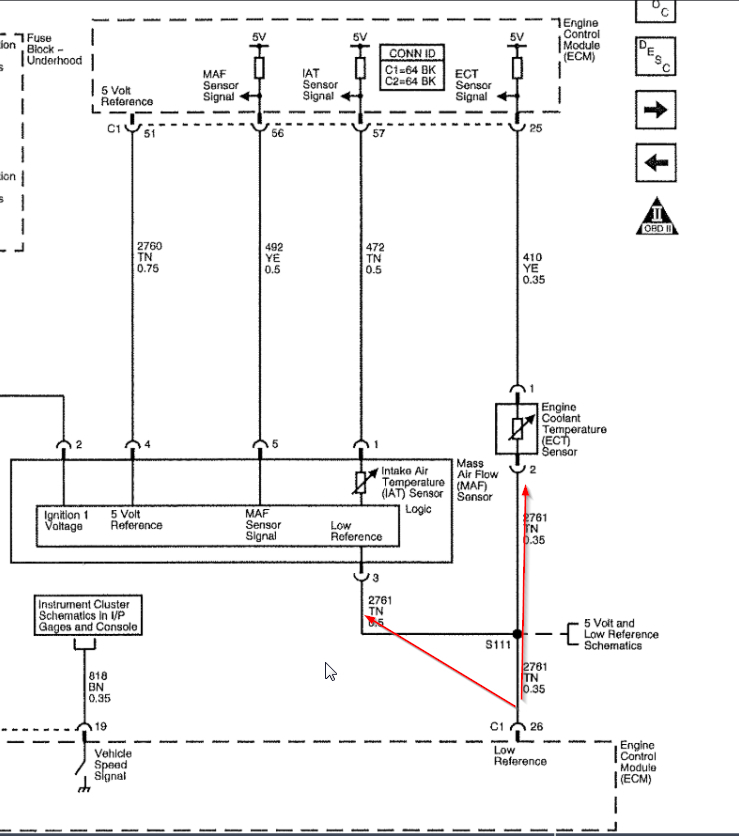
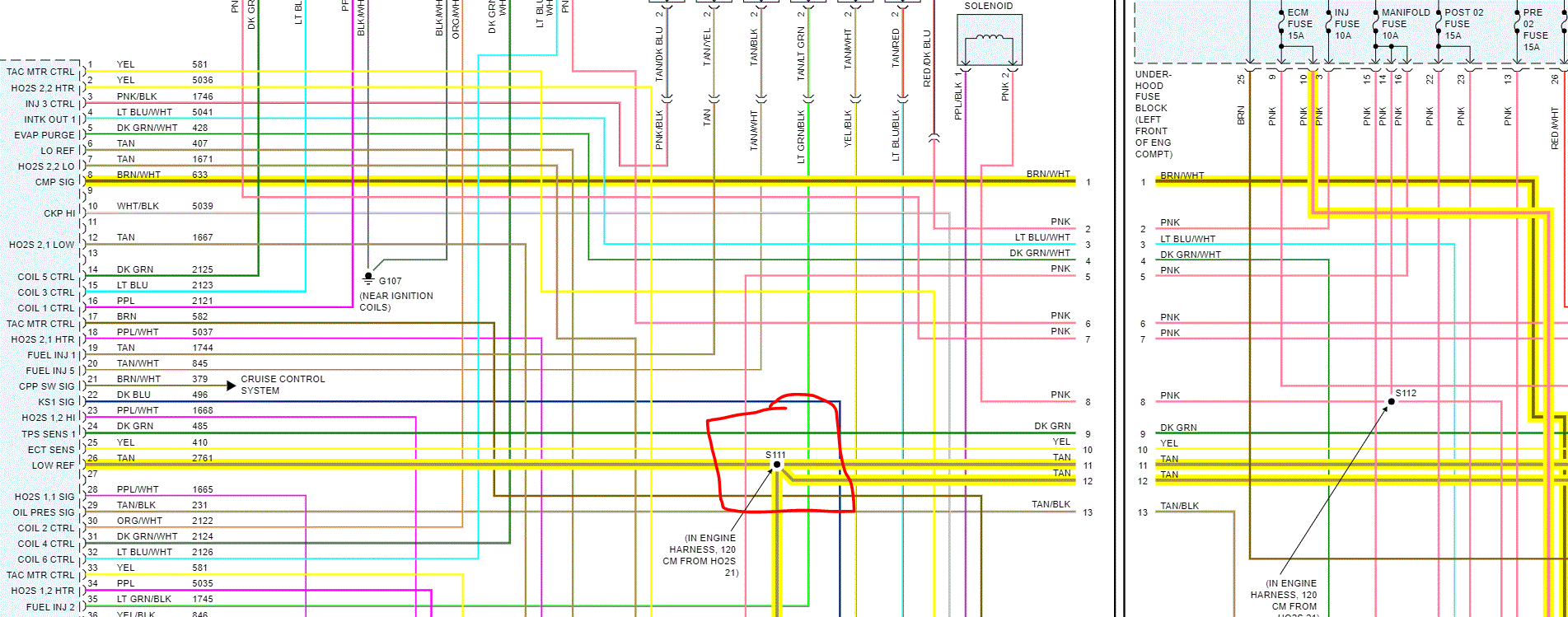
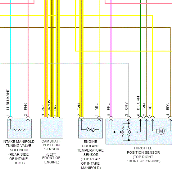
Check out the diagrams (below). Please let us know what happens.
Apr 28, 2020 at 7:46 PM